
Search
The Renewable Energy site for Do-It-Yourselfers
Barra Box --
Change Package A Changes
Change package A included these
new items and changes:
- Add a backdraft damper mounted in
the intake of collector inlet duct just below bottle shelf.
- Add insulation to east, west, and
north walls (not done yet) (1.5 inch polyiso, non-relfective). (now done
Jan 19)
- Add more bottles to fill up the
bottle shelf (now 3 rows of 18 2 litre bottles).
- Remove the external insulation
panel covering the top 7 inches of the collector glazing, and change to the "V"
box arrangement inside the collector (see below).
- Add support for the screen absorber
top and bottom to allow the screen to be fastened better and to position it more
precisely.
- Add support along the top of
glazing and a vertical support in the middle of the glazing to keep it from
bowing inward and to allow better sealing.
- Add temp sensors to first and last
row of bottles rather than just the middle row.
- Add a port on side of collector and
light inside collector to allow the backdraft damper to be observed, add the
duct air velocity to be read through the port on the side.
- Add a seal strip around the top of
the box to provide a flat surface for the lid to sit on.
- Add motor on/off logger to the fan
to allow fan on time to be logged.
- disconnect the bottle temperature
thermal snap switch as a fan control --fan is now controlled only by room temp.
- Generally improve the sealing for
air leaks all around.
- Sprayed some more black paint on
the absorber.
- Replaced the "room" thermostat,
which was not working (Jan 19)
Some Discoveries on Opening the Box
to Install the Change
Many of the bottles had leaked some
of their fluid out. The ones with plain water were OK, but most of the
ones with Cola, Sparkling Water, and Tonic Water had leaked -- some quite a bit.
It appears that all the leakage was
around the bottle cap, and not due to a failure of the bottle itself.
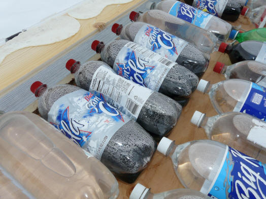
Some of the bottles that had pushed
out some of their fluid. Also tend to bulge the bottoms out.
I refilled all the bottles that were
not plain water and reused them.
Now have 3 rows of 18 bottles each.
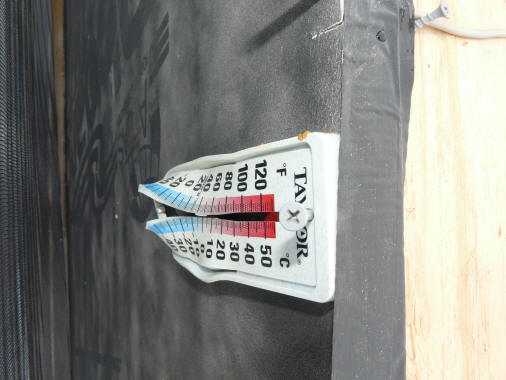
Thermometer at top of collector (just
below bottle shelf) did not fair so well.
The tube was lying broken at the
bottom.
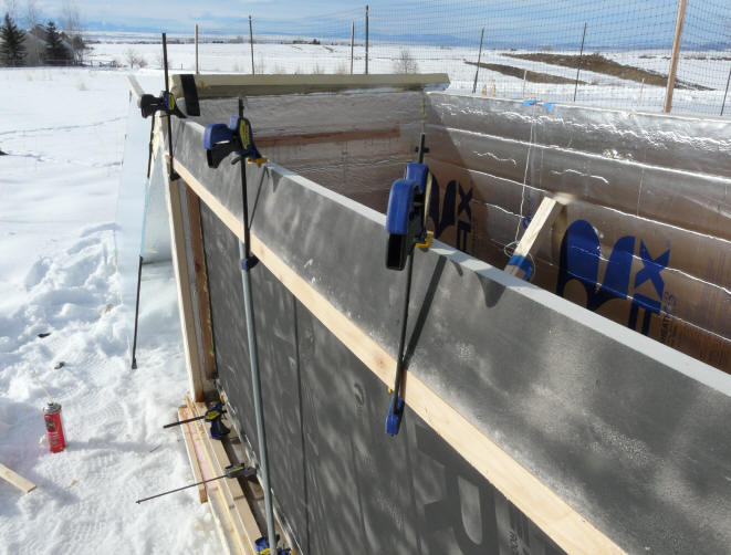
Changes to Collector and Glazing
Added a wood bar about 7 inches down
from top of glazing to support the new "V" box at top of collector, and a
vertical glazing support in the middle (the EMT conduit).
These are both to support the new "V"
box and to keep the glazing from bowing in so much.
Added a wood strip along the bottom
of the absorber (clamps hold it while foam glue dries). This is to have
something solid to staple the black screen absorber to.
This shows the new "V" arrangement at
top of collector -- Nick's idea to get some useful heat out of the top few
inches of collector without losing a lot of heat from the bottle shelf area at
night.
Single layer of screen absorber
stapled in place between the new wood strip at bottom of absorber and the new
wood strip at bottom of the new "V" near top of collector.
The screen was later stapled under
the top wood strip so that at the top of the screen, it is about half an inch
from the glazing. So, flow path is: air enters bottom of collector between
the glazing and the screen. Air rises up through the screen, and
exits the collector at the top behind the new "V" board and then North into the
bottle shelf.
New Insulation on Collector Inlet Duct
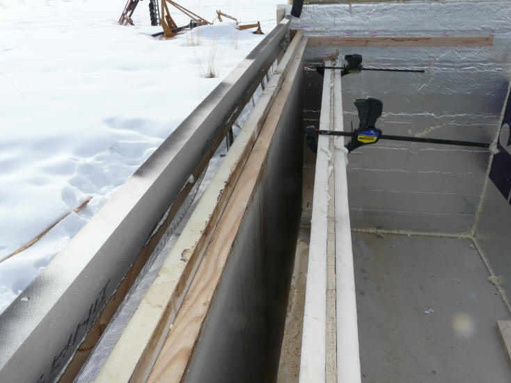
Added new insulation boards on the
south and north sides of the north wall of the inlet duct. There are two
boards, each is 1 inch polyiso -- non-reflective.
Also sealed all the floor to wall and
wall to wall joints with Great Stuff on inside of box.
Backdraft Damper
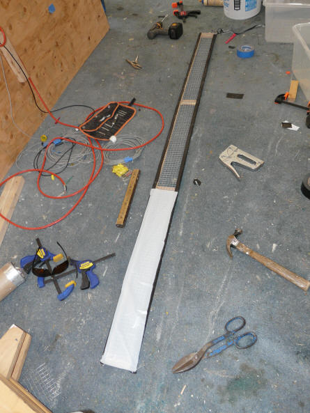
This is the framework for that holds
the backdraft damper. The top part shows the half inch hardware cloth used
to back up the poly film.
Bottom part is getting the poly film.
This backdraft damper frame sits on
top of the inlet duct north wall, and is oriented to allow north to south
flow, but stop south to north flow.
The backdraft damper does not seal
perfectly against backdrafts -- there are very small gaps and cracks around the
edges in places, but it looks pretty good to me. It gets pulled against
the hardware cloth backup as soon as the sun goes off the collector.
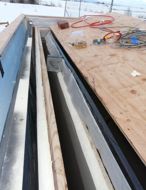
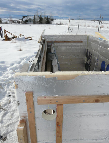
Backdraft damper installed on top of
the inlet duct wall before the bottle shelf is installed over it.
Note the Dwyer Van Meter installed
near the middle.
So, air flow under the bottle shelf
northward through the poly film backdraft damper, and then down the inlet duct,
then under the absorber from north to south, up the south side of the absorber.
When it reaches the top of the absorber, it flow north over on top of the
botttle shelf through the bottles.
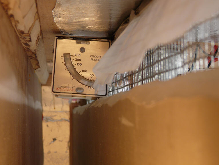
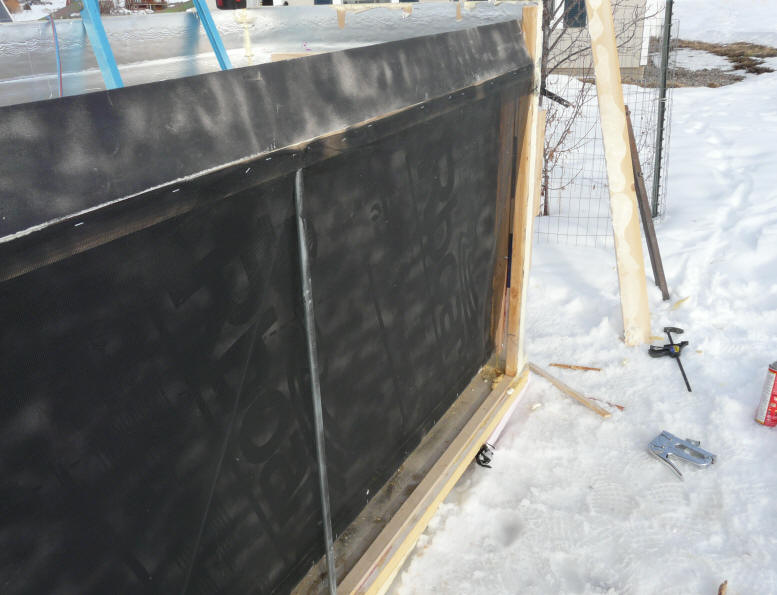
Collector in operation.
Backdraft damper poly film blown out by entering air. Vane meter reading
just under 50 fpm -- probably would be right at 50 if the vane meter were level.
This picture is taken through the
hole in the side of the box shown just below.
Hole cut in side of collector to
allow the performance of the backdraft damper to be observed.
A light is mounted just below the
hole and inside the collector to light the damper and the vane meter.
The hold is plugged with the hole saw
cutout when not taking pictures.
Bottles
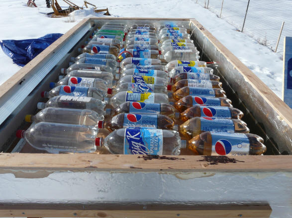
3 rows of 18 2 liter pop bottles
installed on top the bottle shelf.
Also new wood seal strip all the way
around the top of the walls and glazing to make a flatter surface for lid to sit
on -- these are sealed/glued to top of walls with Great Stuff.
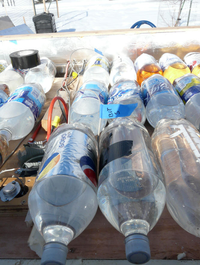
Bottle temp sensors taped to south
row (at black tape), and to north row. Sensor is positioned at the side of
bottle where it contacts the next bottle.
Fan inlet is just visible to left.
The snap disk thermometer switch to
left in foreground is not currently used, but could be used to keep the fan from
turning on when the bottles cool below some set temperature.
For the initial setup, the fan is
unplugged just to give the bottles some time to warm up.
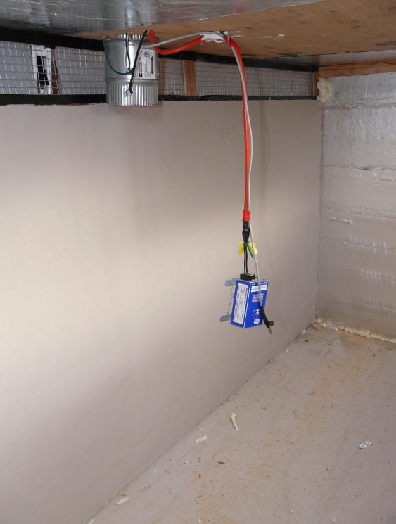
This shows the thermostat in the
middle of the "living room". It is set to about 65F.
The logger sensor that records roomt
temp is the black taped gadget on the grey wire.
Both are about half way down into the
living room.
The collector inlet duct with
backdraft damper is visible at the top of picture.
The fan outlet is also visible.
The small crack between the inlet
duct wall and the floor is calked from the other side.
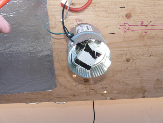
Looking up into the fan outlet with
the motor on/off logger mounted on the end of the fan motor.
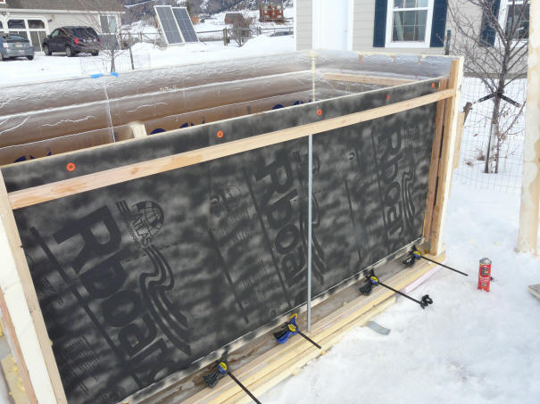
Added Insulation
On Jan 19, added 1.5 inches of
polyiso (non reflective) over the north, east, and west walls.
So insulation levels now are:
- Lid -- 2 inches relfective
polyiso + 2 inches non reflective polyiso
- east, west, and north walls --
2 inch reflecticve polyiso + 1.5 inch non reflective polyiso
- bottom -- 2 inch non-reflective
polyiso + 2 inches extruded polystyrene
Collector inlet duct has 1 inch
polyiso + OSB + 1 inch polyiso
New Room Thermostat
The thermostat shown in the picture
above did not work. Since it was running the fan all the time, I just
unplugged the fan in the interium.
I replaced it with an electric
baseboard style thermostat. As of late Jan 19, its running with the fan
activated and the new thermostat.
Gary January 15, 2010