Search
The Renewable Energy site for Do-It-Yourselfers
$2K Solar
Space + Water: Building the Collector
| This section covers the detailed instructions for building the
collector for the solar space and water heating system.
The collector is built right onto the house south wall. When
installed this way, the wall provides support and stiffness for
the collector, so less material is needed and there and some cost
saving compared to a fully boxed collector. The collector box is
basically just a perimeter frame mounted to the house wall. Using
this arrangement, the collector can be as large as you have wall
for. I think this design also looks better than freestanding
collectors.
This is fifth solar water heating collector I've built, and for
each new generation, I've tried to improve the design over the
previous collectors. I expect that this collector will have a
long life and perform comparably to a good commercial collect (at
about 1/5 th the price).
Back to Table of Contents...
|
|
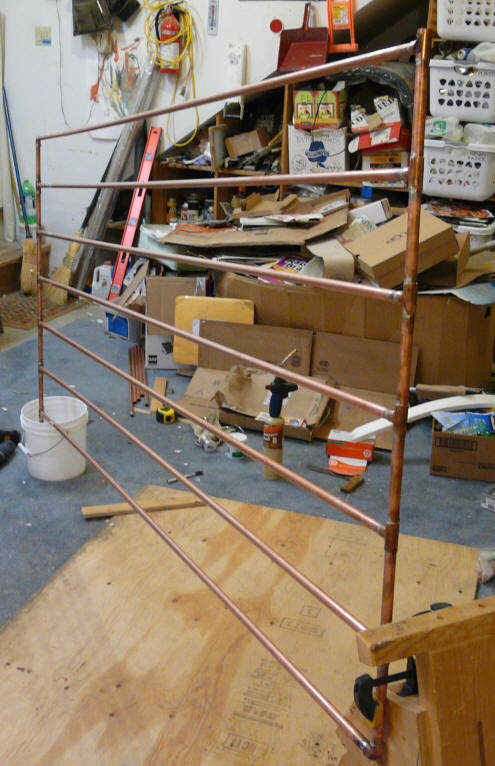
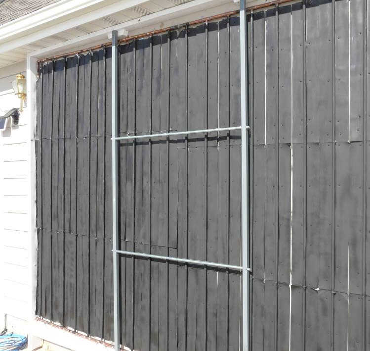
Overview
The two pictures below give an overview of the collector internals and a
view of the completed collector.
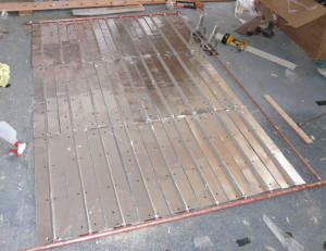
|
Collector box and absorber plate -- ready for glazing.
|
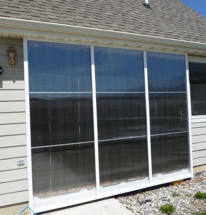
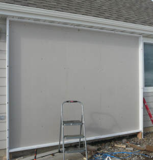
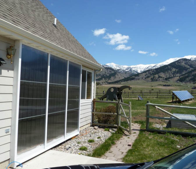
Finished collector with twinwall glazing installed.
|
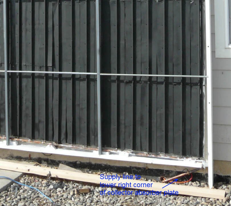
The collector is built right onto the south wall of the house with a
layer of high temperature insulation separating the collector absorber
plate from the siding. The absorber plate is made with half inch copper
riser tubes joined to 3/4 inch upper and lower copper manifolds. Water
enters the lower right corner of the collector and exits the upper left
corner. The absorber plate fins are made from sheet aluminum formed to
fit tightly over the copper risers.
The glazing is UV treated twinwall polycarbonate. The glazing is
supported by the perimeter frame, and by intermediate vertical and
horizontal metal supports.
This collector is a drain back design, so when the pump stops all the
water in the collector drains back down and out the supply pipe in the
lower right corner and into the storage tank, which is located in the
crawl space below and behind the collector.
On this page:
Absorber Plate Construction...
Preparing the absorber fins...
Making the copper pipe grid...
Installing the absorber fins...
Making the collector frame...
Installing the absorber plate...
Installing the glazing and cap strips...
Absorber Plate Construction
| The collector absorber plate's job is to
convert the incoming solar radiation energy into heat and to
transfer this heat into the water being circulated through the
collector.
For this absorber, fins made from 0.018 thick sheet aluminum
which have been painted black are used to absorb the solar
radiation and convert it to heat. The heat is transferred along
the fin to the nearest copper riser pipe, and then into the
circulating water.
|
This is what we are building in this section.
|
Preparing the Absorber Fins
The fins I used for this collector were purchased pre-formed from Tom
Sullivan at the UP
Truck Center in Upper Michigan. Tom worked out a good efficient
tool for making fins when he was doing
his own collectors, and decided to add the fins to the products he
offers from his UP Truck Center. I believe that this is a good option, as
the fins are made from the right thickness of aluminum, come with a very
well formed groove, and are reasonably priced. But, making
your own fins from locally obtained aluminum is also a good
option. I made my own fins for all the collectors before this one, and
can say that you can turn out good quality fins with simple tools. So,
I'd have a look at both options -- price them out in dollars and your
time, and see what comes out the best for you.
The fins for this collector are made from 0.018 thick aluminum, and the
finished width (after forming the groove) is just over 6 inches. This is
about the right
combination of thickness and width. If the fins are made wider than
6 inches, then the fin thickness should be increase accordingly to allow
for the greater heat flow to each riser pipe. Likewise, if the fins are
made narrower, they can be made thinner without sacrificing efficiency.
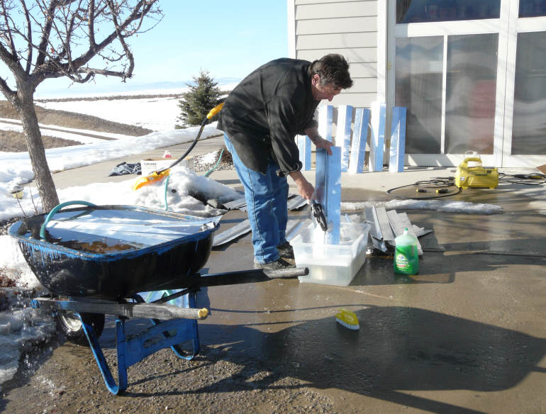
Clean the Fins
The fins come as bare aluminum, and have to be cleaned and then
finished.
The side of the fin that faces the sun gets black paint to absorb
the solar radiation well. The back side that fits over the copper
pipe gets a coat of corrosion resistant primer to provide part of
the protection that prevents galvanic corrosion between the
aluminum fin and the copper pipe.
I washed the fins in water with some detergent. Be sure to brush
the inside of the groove so that the primer will adhere well.
I rinsed the fins with a garden hose, and then left the fins to
dry in the sun.
If you make your own fins from aluminum soffit material (as I
have on the collectors before this one), they come pre-painted and
you can forgo the cleaning and priming step (below). If you use
bare aluminum to make your fins, then you do want to do the
cleaning and priming.
|
|

|
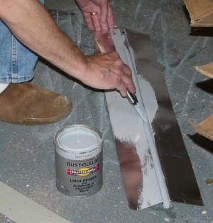
Prime the Fins
I used this Rust-Oleum aluminum primer to prime the back side of
the fins. Pay particular attention to getting the primer to coat
the full inside surface of the grooves.
A Zinc-Chromate primer would probably be an even better choice,
but these have become more difficult to come by due to
environmental concerns. The primer I used was available at the
local hardware.
The combination of the primer plus the silicone discussed below
serve to prevent the entry of water into the fin to copper tube
joint area. This prevents any tendency for
galvanic corrosion.
Once the fins are all cleaned and primed on the back side, set
them aside for later.
|
 |
Making the Copper Grid
|
The copper pipe grid is made with half
inch copper pipe risers soldered to 3/4 inch copper header
(manifold) pipes. I used the regular Type M copper pipes intended
for residential plumbing jobs.
For the joint between the risers and the
manifolds, I used standard reducing Tees. This is a nice straight
forward way to make the connection, and requires only simple
soldering skills.
The reducing Tees can be quite expensive
depending on where you buy them, but I found that PEXSupply.com has a nice
price on them in quantities of 25.
Be VERY careful to order the type with
3/4 inch on the straight through part, and 1/2 inch on the branch
-- the pictures on the PEX Supply web page are make it easy to
order the wrong ones -- I ended up calling them up to make sure,
and was glad I did as I had picked the wrong version.
There are alternatives to using the
reducing T's -- for example, Ken
worked out a very nice T-Puller...
|
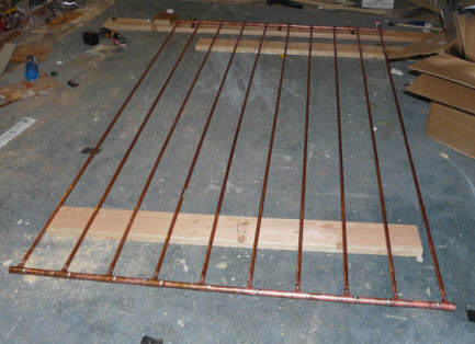
This is what we are making in this section. |
Laying Out the Copper Grid
First, establish the overall size of your
collector. The things to bear in mind when setting the overall size:
-
The wall (or other) space you have
available.
-
Allow for drain back slope: the bottom of
the collector must be high enough to allow for the collector supply
pipe to slope downward from the collector toward the storage tank at
about 3/16thsinch per foot so that the collector drains back to the
tank when the pump shuts down.
-
Efficient use of materials is a
consideration -- try to choose the size to avoid a lot of waste.
-
I For wall mounted collectors, its important
evaluate the roof overhang and make sure that not too much of the
collector will be shaded when the sun is high in the summer. These overhang shadow tools
will help you do this...
-
See the System
Design Section for more on performance vs size of collector ...
All of the above will allow you to establish
outside dimensions of your collector frame.
Now, establish the height and width available
inside the collector frame by subtracting the thickness of the perimeter
frame. The copper grid must then fit inside this space with some
allowance for clearance and for the tilt of the copper grid for drain
back. Layout a rectangle on the shop floor that is the size of the inside
of your collector frame.
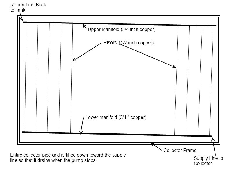
Figure out where the supply line is going to
come into the collector. This must be either the left or right lower
corner. The lower manifold will be sloped down toward this corner so that
the collector will drain fully when the pump is turned off.
The return line from the collector must then
connect to the opposite upper corner (that is, if the supply comes into
the lower right, the return must leave from the upper left).
Take the pipe you plan to use for the lower
manifold, and place it in the proper position on your floor layout. This
lower manifold must be sloped by about 3/16ths inch per foot of width
toward the corner where the supply pipe comes into the collector for
drainage. The lowest part of the manifold should clear the collector
frame by about an inch -- this will be at the corner that the supply pipe
comes in. If the manifold is (say) 12 ft long, then the supply end of the
manifold will be about 1 inch above the lower collector frame board, and
the far end of the lower manifold will be (12)*(3/16 Inch) + 1 inch = 3.25
inches above the inside of the frame. Allowing enough slope for good
drain back of the water in the collector is critical for freeze protection
in drain back collectors.
Now layout the top manifold in the same way.
For our 12 ft wide example, the manifold will have about 1 inch clearance
to the top frame on one end, and 3.25 inches clearance on the other end.
It will be parallel to the bottom manifold so that all of the risers can
be cut to exactly the same length.
Now lay in the left and right end riser pipes.
They should be perpendicular to the manifolds, and approximately 3 inches
in from the left and right frame edges. Note that because the manifolds
are tilted with respect to the frame, the riser pipes will be tilted with
respect to the frame sides. Now take a few of your fins, and lay them out
left to right across the full width of the collector. The left most fin
and right most fins should have their grooves centered over your left and
right risers. If the spacing does not come out to an even number of fins,
then you can move the end riser a little to make things come out even. If
you end up moving the end risers out a bit to get an integral number of
fins to fit, then the two end fins can be trimmed with tin snips to fit in
the available space. This does not have to be exact -- if there ends up
being a slight overlap of the fins on each other, or a slight gap between
fins, that's OK -- but, if its more than an 1/8 inch, I'd do some more
fussing around.
Now that you have everything laid out to fit on
the floor, measure the length of the risers, and the length of the short
pieces of manifold pipe that will go between the reducing T's. Be sure to
allow for the length provided by the fittings themselves. Its best to do
a trail cut of a riser, and a couple of the manifold short pieces, and do
a trial fit over your floor layout to make sure you have the lengths
right.
The description above makes this all sound more
complicated than it is. Just start laying it all out on the floor, and
you will quickly see where its going. The most important thing is to make
sure that the collector grid of pipes has down slope so that it will drain
properly, and that it all fits inside the collector frame.
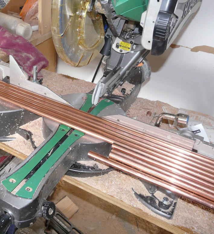
Cut the Riser and Manifold Pieces
Cut out all the risers for the collector -- they will all be the
same length.
There are several ways to make all these cuts.
If you have a regular wood working cutoff saw, I find that works
fine for cutting all the risers at once.
One thing to be careful of is don't count on the nominal 10 ft
pipe lengths to be exactly 10 ft. The 10 ft pipe lengths I bought
varied by as much as half an inch from each other. Basically this
means that if you want a bunch of 9 ft lengths, its NOT safe to
set up a stop to cut 1 ft off your 10 ft lengths!
You can also use an electric saber saw, or one of the cutter
wheel type copper pipe cutting tools that plumbers use.
Now, cut out the short pieces of the manifold pipes. I used my
wood working cut off saw with a stop set to the right length to do
the cutting -- this is fast and assures that all of the pieces
will be the same length.
|
 |
 |
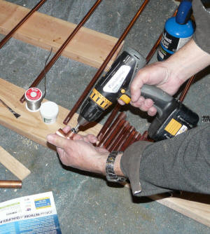
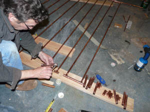
Soldering the Grid
I think that I counted about 130 solder joints
in the whole grid, so its important to have a good system both to speed up
the work and to avoid leaky joints.
The most important thing to remember is to clean
and flux each joint carefully. If the joints are cleaned and fluxed
well, the actual soldering is easy, and the likelihood of a leaker is
small.
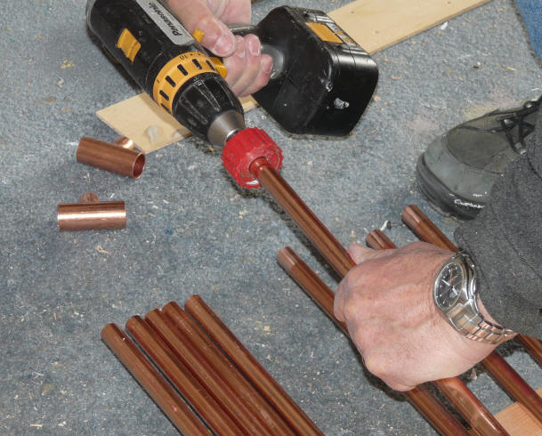
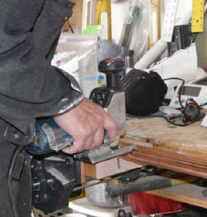
Clean all the fittings
Clean all of the pipe ends and the T fittings carefully. I use
the wire brush tools, but sand paper can also be used.
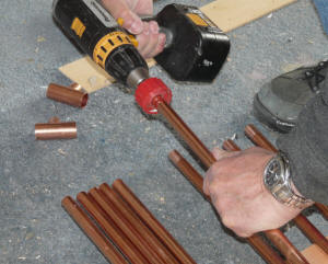
There are lots of fittings to clean, so mounting the brush to the
drill saves some time for the half inch pipes and fittings -- it
was a bit too much torque for the 3/4 fittings.
Do all the pipes and fittings for one manifold, and then solder
all of those connections, then move on to the other manifold.
This way the fittings don't sit around a long time after cleaning.
|
Cleaning the inside of the T's with wire brush |
|
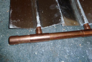
Terminating the Open Ends of the Manifold
The supply line from the pump will come
into the bottom manifold at one corner. The return line from the
collector leaves the top manifold of the collector at the opposite
corner from where the supply comes in.
This diagonal arrangement between the
supply and return lines insures that the total flow path through
each riser is the same, and that helps to make sure each riser
gets the same amount of flow.
There will be two manifold ends don't
get either a supply or return line. For these corners, its best
to use one of the reducing Tees and terminate the unused branch
with a cap or plug. If you use a reducing elbow to go from the
3/4 inch manifold directly to the last half inch riser, that riser
will get more flow than the others because it has less flow
resistance. Keep the dead end short, as it could be an ice
accumulator.
|
 |
Flux all the Joints
Apply soldering flux to all of the cleaned fittings and pipe
ends.
Don't miss any!
|
 |
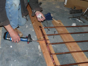
Solder the Joints
Now push all the joints firmly together, and solder each joint.
If you have not done any soldering before, not to worry. There
are lots of good "how to solder" videos that are only a Google
away. Practice on a scrap to get the feel.
After the solder joints cool, wipe them off with a wet rag to
remove the corrosive flux leftovers.
If you did the cleaning and fluxing carefully, you will probably
end up with no leaking joints -- but, be sure to do the leak test
below.
I used ordinary plumbers solder. If you have a choice of solder
melting temperatures, I would pick the highest melting point
solder of the ordinary solders -- probably not worth it to go to
an exotic high melting point solder.
After finishing the first manifold joints, repeat for the other
manifold.
Be sure you solder every single joint -- its surprising how easy
it is to just completely miss soldering a joint -- these tend to
leak :)
|
 |
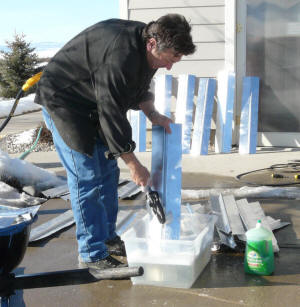
Leak Test
At this point, you want to test for leaks. Its tempting to skip
this leak test, but don't -- its much easier to fix a leak now
than after you have the grid mounted in the collector frame.
To do the leak test, I just plug the return line, then stand the
collector up on its side with the supply connection up. I then
use a funnel and a bucket of water to fill the whole grid with
water -- be sure to get the air out. Then let it set for an hour
or so and look for leaks and make sure the water level has not
gone down. If you have an easy way to pressurize the collector
for the leak test, so much the better.
Its very important to catch any leaks now. Even very small leaks
can cause subtle flow problems later. Sometimes small leaks will
suck in air, and this can cause the pump to loose prime or cause
uneven flow to the risers -- these things are a pain to find and
fix after the absorber is installed, so be sure to do a good leak
test. A test that actually pressurizes the absorber grid is
better than the simple test I show here.
|
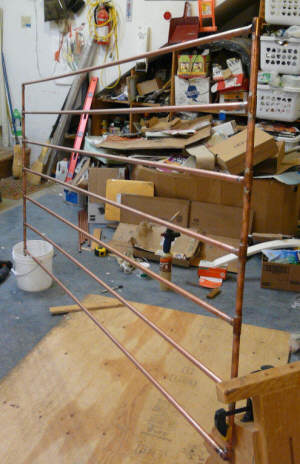
Picture of a previous collector being leak tested |
Installing the Heat
Absorbing Fins on the Copper Grid
From a performance point of view, this is
probably the most important step in building the collector -- securing the
fin to the riser tube in a way that will perform well thermally for 50
years.
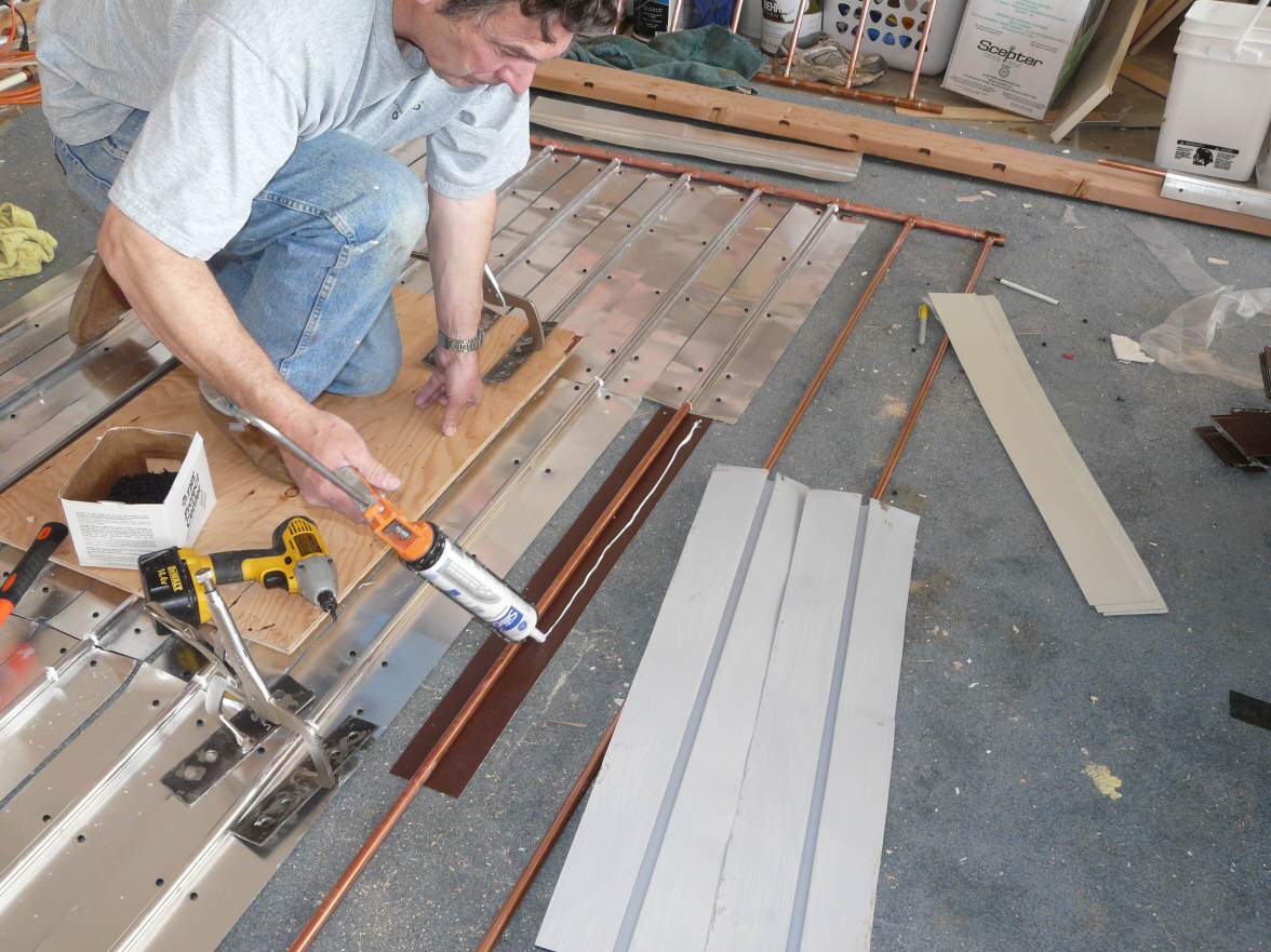
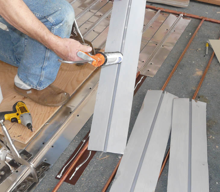
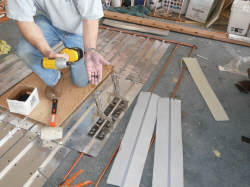
Install Backing Strip
Place a 3 inch wide strip of 0.018 thick aluminum under the riser
pipe where the next fin is to be installed.
Put a bead of silicone along each side of the fin as shown in the
picture.
An alternative to using the
backing strip...
|
 |
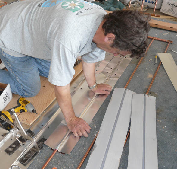
Press the Fin Onto the Riser
Press the fin onto the riser pipe with the 3 inch flat strip
under the riser.
Firm down pressure with your palms is all that is needed.
|
 |
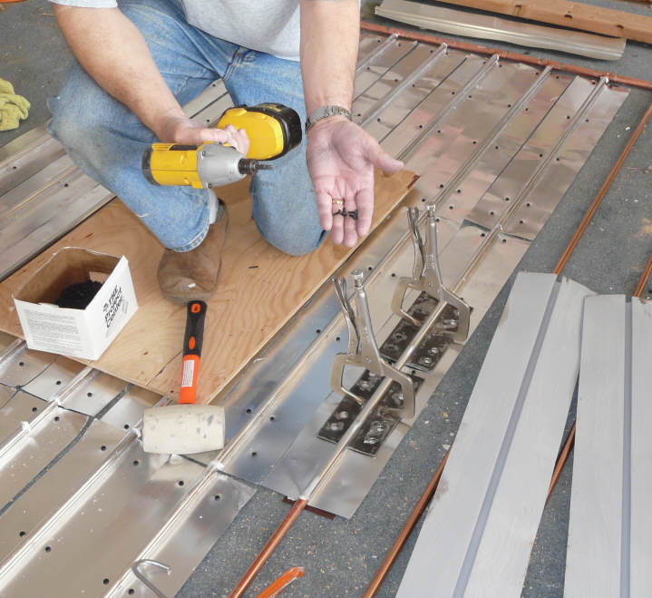
Clamp the Fin to the Riser Pipe
Clamp the fin very tightly around the riser pipe. When you look
at the fin from the end, you should see no gap between the fin and
the riser pipe.
The picture shows
Tom's modified vice grip clamps, which work very well. But,
you can make
simple clamps that will also do the job... But, either way
its important to have a means to tightly clamp the fin to the
riser pipes.
Once the fins are tightly clamped in place, use short sheet metal
screws to secure the fins to the backing sheet. Use the screws in
pairs directly across from each other as shown in the picture.
The backing plate provided a tension tie across the bottom of the
fin to keep it tightly camped in place.
Some have suggested that pop rivets would work instead of the
screws, and I'd guess that this is true.
|
|
 |
You should end up with an absorber grid that looks something like this.
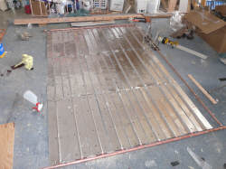
Nearly finished absorber grid. |
showing the fin, riser, strip under riser
and the screws that hold the fin to the
flat strip. |
You can either paint it it black now, or wait
until after its installed in the collector frame.
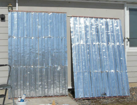
I built the absorber plate in two halves to make
it easier to handle and move and get out of the shop.
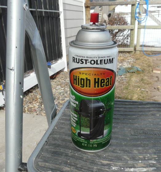
I use the Rust Oleum high temperature barbeque
paint in the flat finish in spray cans. I've used this paint on a number
of collectors with no problems.
After painting, its important to place the
absorber plate in the sun and allow it to bake for a day before putting
the glazing on -- this make sure that all the volatiles are baked out, and
will not coat the back of your glazing.
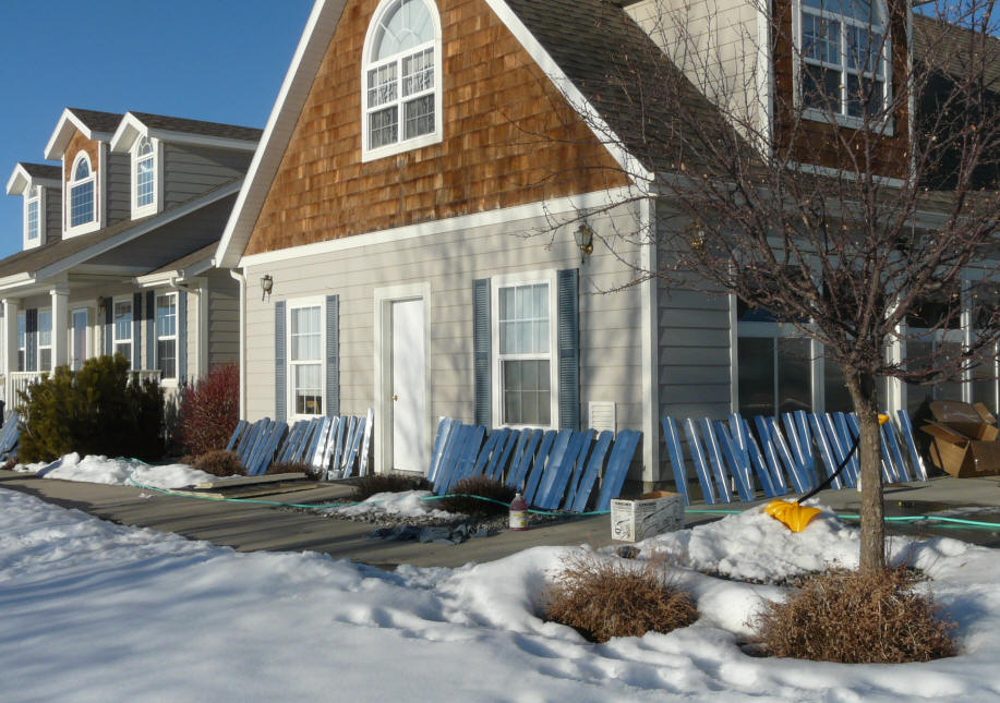
Making the Collector Frame
| This section details making
the collector frame.
In this case, the collector frame is mounted right to the house
south wall. This allows the south wall to be used for support and
saves some material. I also like the look better than separate
collectors.
Mounting the collector vertically has some impacts on
performance, and you should read over the section on collector
sizing to understand the performance issues. Be particularly
careful if you have a deep roof overhang, which can cause
excessive shading.
The frame is very simple -- basically just a wood perimeter frame
made from 2 by lumber.
|
This is what we making in this section |
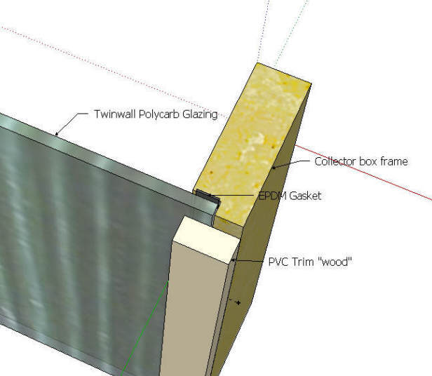
Collector box side frame, glazing, gasket, and cap strip.
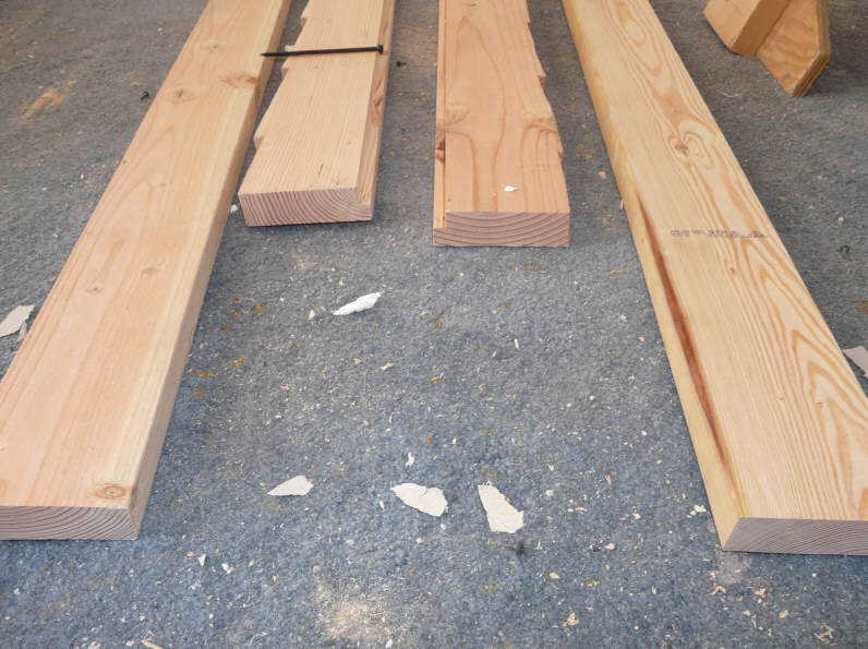
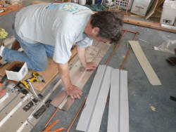
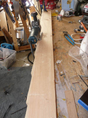
Cut the Side Frames
The collector frame is made from ordinary 2 by 6 lumber. Pick
through the pile at the lumber yard and get some good ones --
straight and relatively free of knots and defects.
Cut the two side frames to length. In my case, the side frames
run from just above ground level right up to the eave soffit.
Rip the side frames to a width of 5 inches.
If you don't have a table saw to rip these boards to width, see
the alternative below.
|
 |
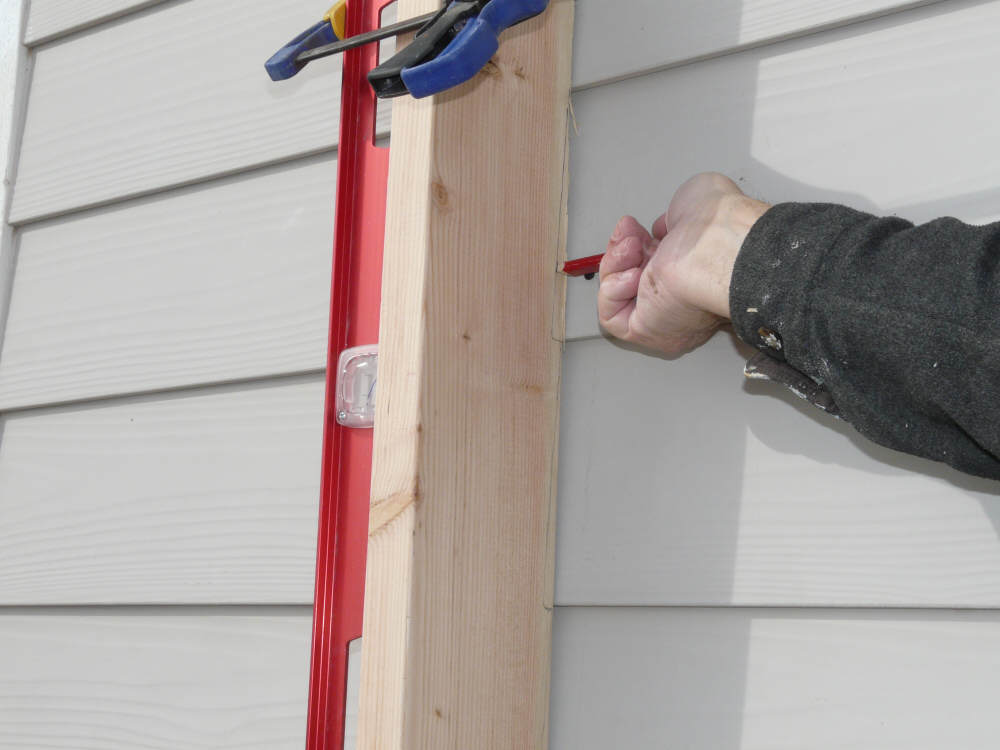
Scribe the Side Frames to the Siding
I scribed and cut the side frames to match the beveled siding on
the house. To do this, prop the side frame into position against
the wall, and scribe a line onto the frame using the siding as a
guide.
Then cut the scribed line using an electric saber saw.
This scribing operation is not really necessary for most siding
(including mine) -- the idea was to make it look a little neater,
but some careful use of caulking would probably work about as
well.
|
 |
 |
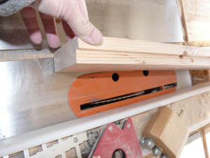
Groove the Side Frames for the Glazing
The side frames have a groove or rabbet to accept the
polycarbonate glazing.
The groove can be made easily on the table saw by setting the
fence and blade depth appropriately and running the frame through
once for each side of the groove.
I made the groove about 3/4 inch wide, and just over 3/8 inch
thick to accept the 10 mm twinwall glazing.
If you don't have a table saw, see the Simple
Tools version note below.
|
 |
Cut the top and Bottom Frame Members
Cut the top and bottom frame members to match the width inside
the two side frame members as shown in the picture.
Rip the of the upper and lower frame members to width such that
they are flush with the bottom of the glazing groove in the side
frame members, this will be about 4 and 5/8 ths inches, but may
vary a bit depending on your siding.
This is a good time to prime and paint the frame carefully. Use
two coats of high quality exterior paint.
If you don't have a table saw, see the Simple
Tools version note below.
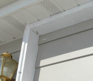
Note that the top of this collector is protected from the
weather by being tucked up under the eave. If the top sill of the
collector was exposed to the weather, I would have used a
top sill similar to this collector...
|
 |
 |
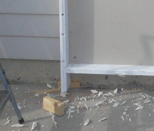
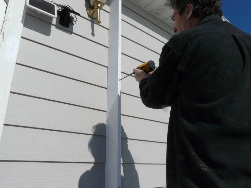
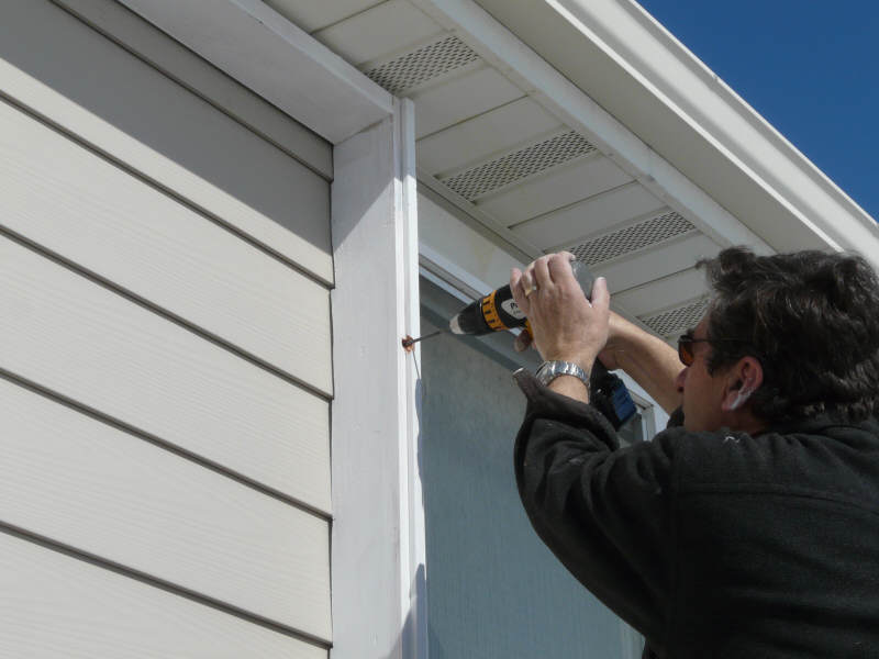
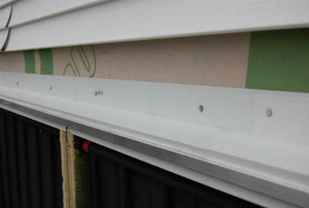
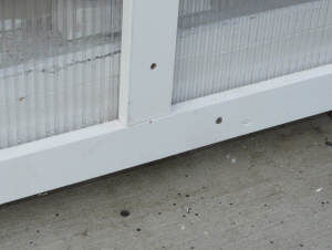
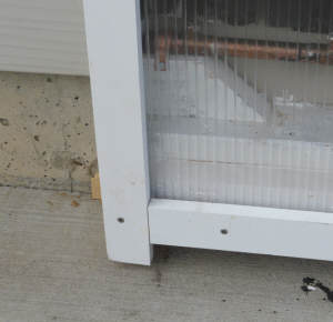
Install the Frame on the Wall
Start by propping the left side frame member up against the wall
in the correct position. Use a level to make sure its plumb.
I used long screws (called log screws locally) to secure the
frame to the house. The screws need to be long enough to go into
the sheathing under the siding.
Once the frame member is in position, drill a pilot hole through
the frame and siding. Then using around a 5/8 spade bit, drill a
countersink hole so that the screw head will be below the surface.
Drive the screws in until the frame is solidly attached to the
wall. With a few screws, this make a very solid mount.
Now install the top and bottom frame members in the same way,
making sure they are level.
Then using the top and bottom frame members as a guide, install
the right side frame member.
|
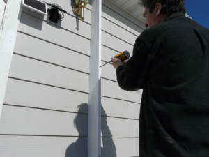
Driving a screw in for first frame member |

Countersink hole for final frame member. |
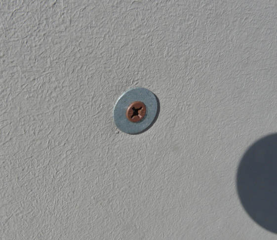
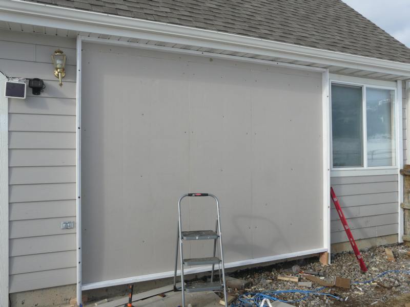
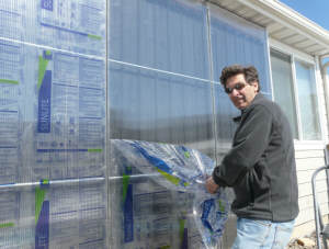
Install the Insulation Board
The insulation board isolates the siding and house wall from the
collector.
Use polyisocyanurate rigid insulation board. If you use the
blue, pink or white polystyrene insulation board it will melt --
trust me on this. The polyiso is a little harder to find, but
most lumber yards have it -- it often has reflective aluminum face
sheets.
The polyiso insulation board shown in the pictures is Atlas
R-Board.
Cut the insulation board to size, and secure it with screws. Use
washers under the screw heads to spread the load to a larger area
of the weak insulation board.
|
Placing the insulation board |
Screws with washer. |
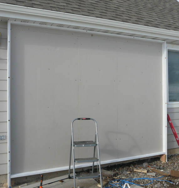
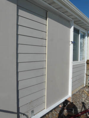
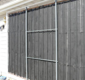
Caulk the Frame
Caulk all the edges where frame meets the siding to keep the
weather out.
You should end up with something like the picture to the right.
.
|
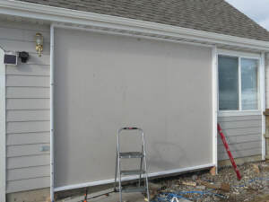
Ready for the absorber and glazing |
Install the Absorber Plate in the Frame
| This section details
installing the absorber plate into the collector frame.
The key thing on the installation of the absorber plate is to
make sure that it is installed with adequate down slope toward the
supply line so that it drains completely when the pump shuts off
for freeze protection.
The down slope is accomplished by slightly clocking the whole
absorber plate assembly so that the manifolds slope down toward
the supply pipe corner.
You will want to look ahead to the plumbing section, and figure
out where your supply and return lines are coming in. You may
have to do some of this supply and return plumbing before you
place the absorber plate in the collector.
The absorber plate is mounted on blocks that support it, but also
allow it to move around a bit as it expands and contracts.
|
 |
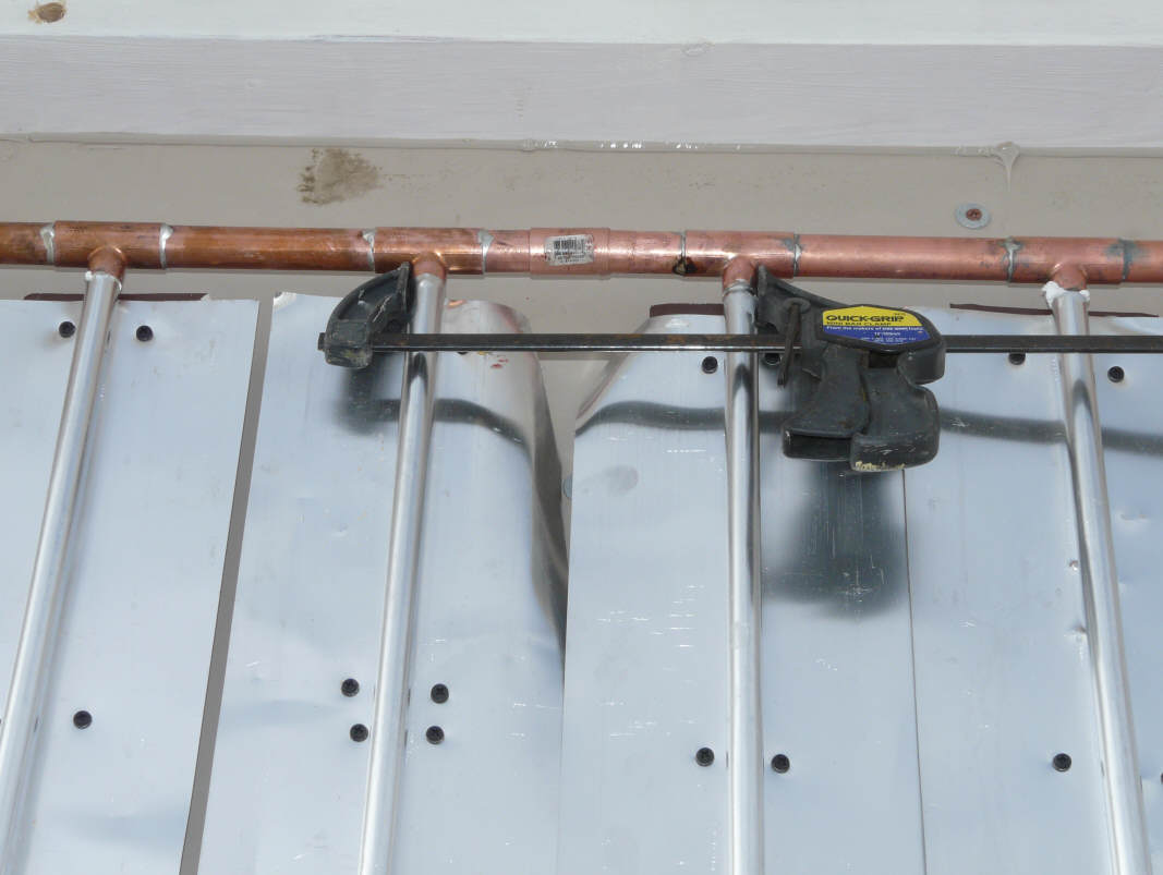
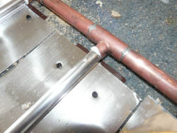
Join the Sections of the Absorber Plate Together
If you built the absorber plate in sections for easier handling,
place the sections in the collector frame.
Using a regular solder coupling, clean, flux and solder the
couplings together.
A clamp is helpful for pulling the sections together, but don't
overdo.
If you think that for some reason you may want to be able to
remove each section at a later time, you could use solder unions
here, but the regular couplings seem fine to me.
|
 |
Joining the two sections with a soldered coupling |
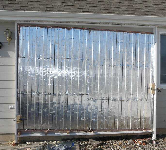
Paint
the Absorber
If you have not already painted the absorber, do so now.
I used Rust Oleum high temperature barbeque paint. I've used
this on several collectors and it appears to work well.
Lately I've tried the alternative of having the paint department
at Home Depot mix up a gallon of black flat exterior latex paint.
This appears to work well, and has the advantages that is cheaper
and it does not stink. But, I've not had a collector like this
operating long enough to know how it holds up -- I'm thinking it
will probably be fine. If you are painting bare metal fins, it
may be necessary to prime them before painting with the latex
paint?
Spray painting with a paint sprayer would be another good option
for a large absorber plate.
After the paint is on, be sure to let it cure in full sun for a
day. You don't want to apply the glazing until the paint is fully
cured. Else, it may deposit volatiles on the back or your new
glazing.
|
 |
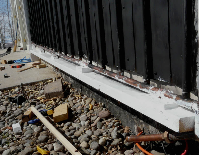
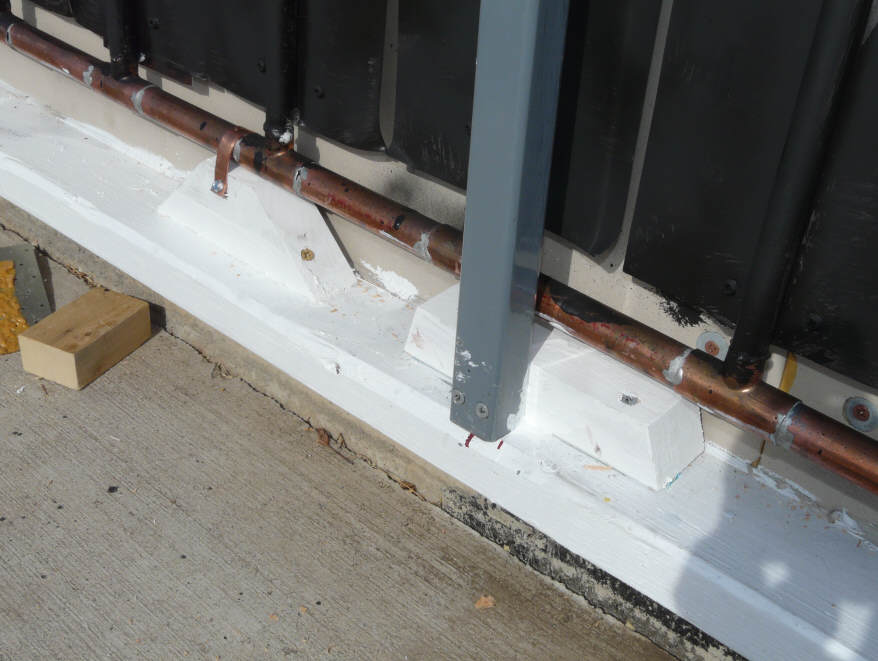
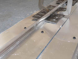
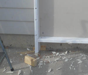
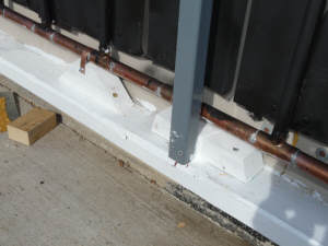
Install the Lower Support Blocks
The absorber plate is supported by a series of support blocks
below the lower manifold. The height of the blocks increases as
you go from the supply pipe end of the collector to the opposite
end -- it is this increase in height that provides the drain back
slope. The slope should be about 3/16 ths inch per foot of
manifold width.
The manifold is clamped to the blocks with copper strapping. The
strapping keeps the manifold in place, but is loose enough to
allow expansion and contraction.
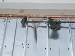
The top manifold is held in place by some ordinary large copper
pipe clamps. These do not support the manifold, but just keep it
from tipping outward. The full weight of the absorber plate is
supported by the blocks under the lower manifold.
The absorber grid is supported in this way so that it can expand
and contract as it heats and cools without overstressing it.
|

Support blocks along bottom of collector |
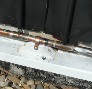
Close-up of the support block and clamp strap |
Collector Glazing and Cap Strips
| This section covers
installing the glazing supports and the glazing.
This collector is glazed with three sheets of 10 mm thick
twinwall polycarbonate glazing.
Vertical supports must be added to support the vertical edges of
the twinwall panels. Lightweight horizontal supports are also
used to control the tendency of the panels to bow inward as they
are heated.
To hold the twinwall panels in place, cap strips made from
plastic wood are used.
|
This section covers installing the glazing. |
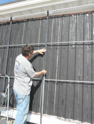
Install the Intermediate Vertical Supports
The outer edges of the outside panels sit in the grooves in the
collector frame, and the top and bottom of all the panels sit
directly on the collector frame top and bottom sills. But, two
additional vertical supports are needed to support the middle
panel vertical edges and the outside panel inside vertical edges.
I used two square steel extruded sections with a 1.25 outer
dimension. The wall thickness is about 0.1 inch. I used these
steel sections because they are straight, strong, and fit in the
limited space in front of the absorber (I wanted the absorber to
be continuous across the full collector).
The vertical steel glazing supports are secured to a block of
wood that is in turn screwed and glued to the collector box
sills. This allows easy removal if the absorber ever has to come
out. Alternately (probably better) would be to make these blocks
from the cutoffs from the steel glazing support tubes.
The steel sections get a couple coats of Rust Oleum enamel.
This is the first time I've used this kind of glazing supports,
and I'm quite happy with the results. The collector glazing is
well supported and stays flat as a pancake.
|
 |
 |
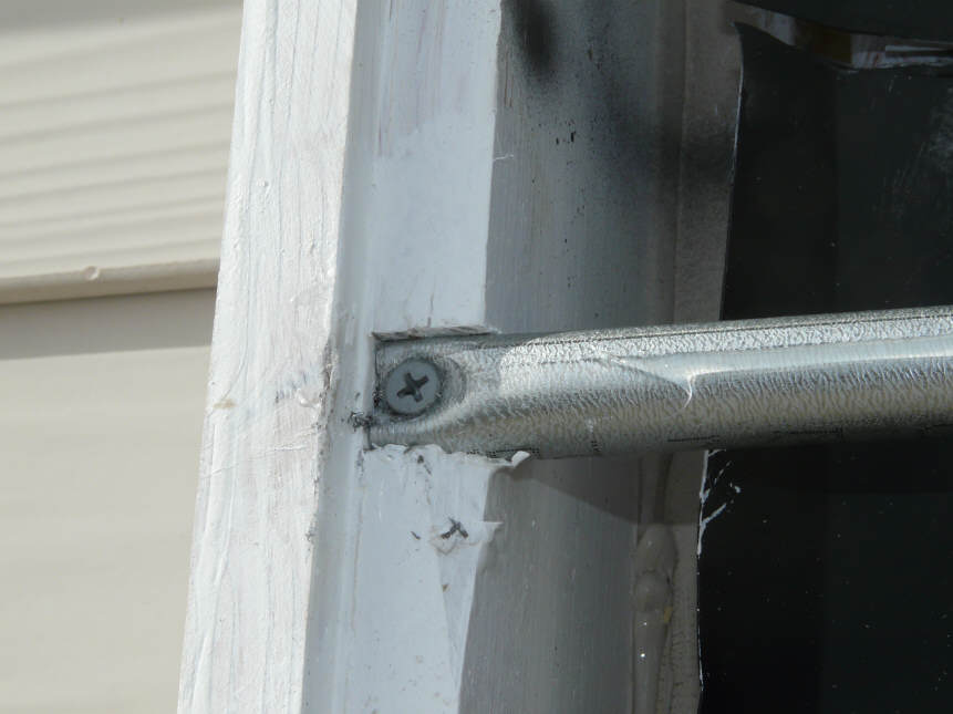
Install the Horizontal Glazing Supports
Lightweight horizontal glazing supports are added at about the
1/3rd points in the twinwall panels. These supports control the
tendency of the twinwall to bow inward as the collector heats up.
I use thin wall EMT electrical conduit, which is straight, cheap,
readily available and galvanized for rust protection.
The inner end of the EMT is supported by drilling a hole through
1.25 inch square steel extrusion to accept a length of threaded
rod. The nuts are installed on the threaded rod, and the EMT is
just a tight friction fit over the nuts. See the picture to the
right.
The outer edges of the EMT is simply installed a small notch cut
in the collector wood frame and secured by a screw.
I place a thin bead of silicone caulk along the front face of the
EMT to cushion contact with the twinwall.
I used these EMT supports on the Solar Shed collector, and they
have been working fine for more than 5 seasons with no sign of
problems.
|
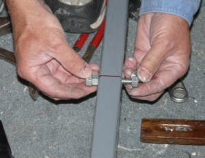
Threaded rod and nuts that support the
glazing support tubes. |
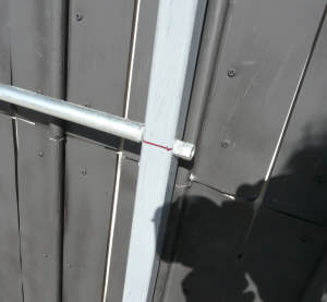
Middle attachment of horz glazing support |
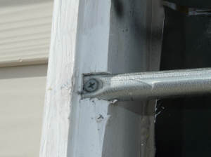
Outside end attachment of horz glazing support |
Install the EPDM Gaskets
I used EPDM rubber gaskets to between the glazing supports and
the twinwall panels.
The EPDM was just strips cut from scraps of the EPDM tank liner
(see the tank section).
To hold the EPDM in place, I used a bead of silicone caulk on the
glazing supports, and just pushed the EPDM into it (picture).
I used the EPDM gaskets along all of the glazing supports (top
and bottom sills, edge frames, and steel supports), but not on the
EMT horizontal supports.
The twinwall panels are just pushed into the EPDM strips by the
cap strips -- no adhesive is used to hold the glazing in place --
so, its each to take out if need be.
In the past, I've just mounted the twinwall directly onto the
wood glazing supports using cap strips, and this worked fine, but
I thought the EPDM would give a little better a seal and a little
more flexible a mount.
.
|
 |
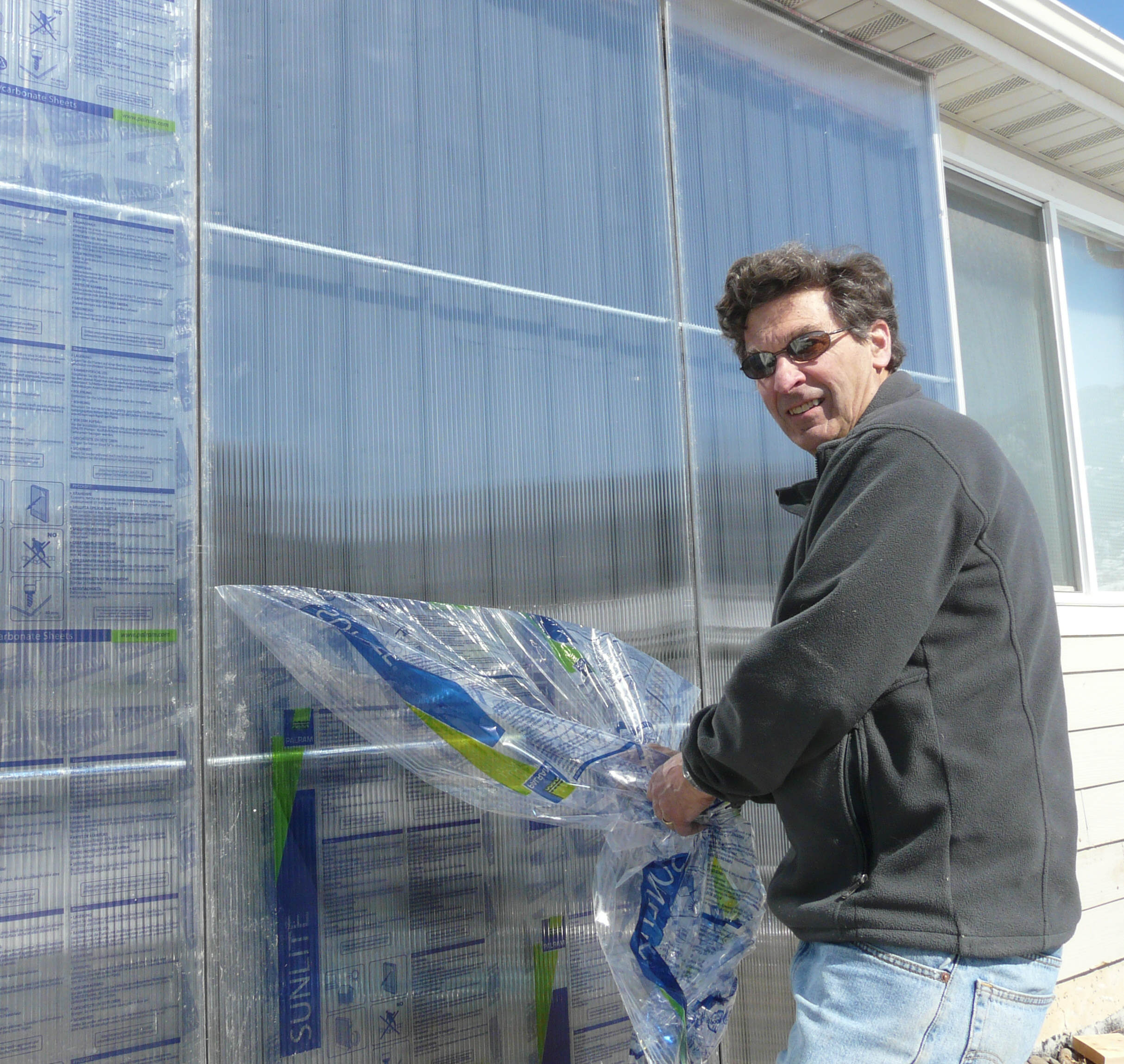
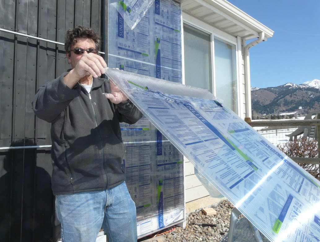
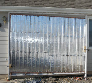
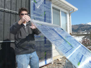
Install the Glazing and Cap Strips
The first step in installing the glazing is to seal off the top
and bottom of the twinwall panels with aluminum tape (pic to
right).
Tear of the inner protective plastic wrap on the twinwall panel.
Make sure that the side that has the UV protection faces out --
just follow the "this side out" label.
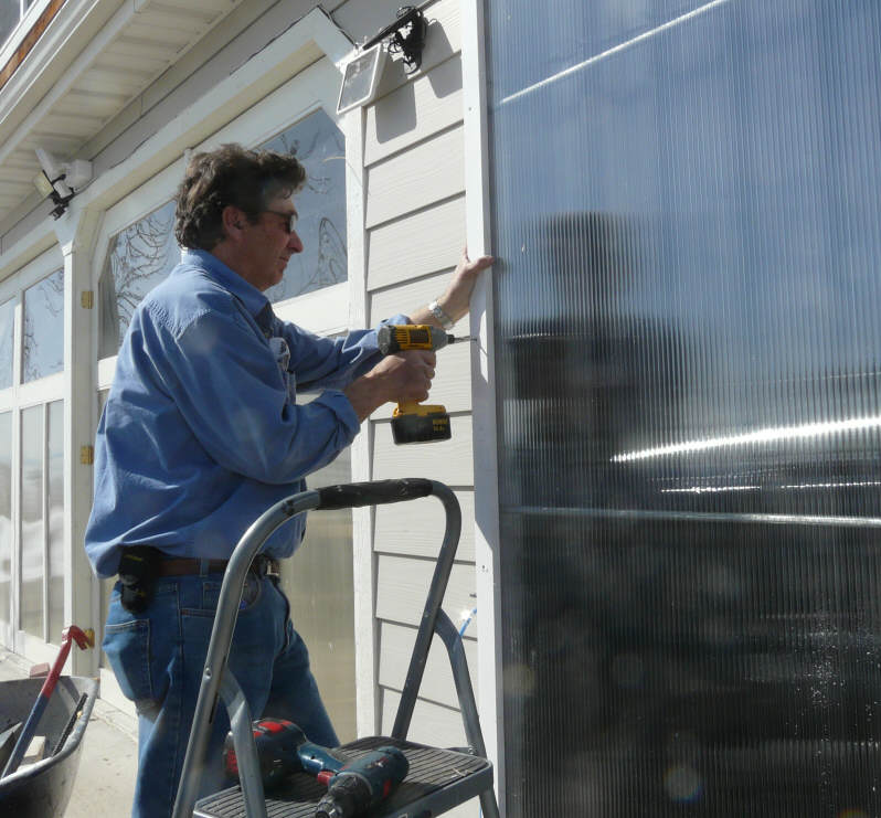
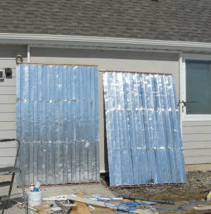
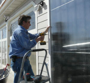
Next, clamp the left twinwall panel on the supports. Make
certain that the right vertical edge is properly aligned on the
steel support. There should be a small gap between the panels
where they meet on the steel support (about 1/8 inch). Once
everything is lined up, install the cap strip over the left edge
of the panel to hold the panel in place. This is where you will
find out how good a job of plumbing the steel supports you did :)
I used the PVC "wood" that is sold for house trim instead of real
wood. My experience is that wood cap strips have a short life.
I attached the cap strips with stainless steel wood screws on the
outer edges.
To attach the cap strips to the steel supports, I bought 1/4 inch
stainless bolts, and installed them in holes that I threaded for
the bolts in the steel supports.
The cap strips should be snugged into place, but not overly
tightened.
The top and bottom cap strips are installed in the same way.
I know that some twinwall glazing instructions talk about
allowing for the panels to expand and contract and that there are
some fancy mounting systems that are supposed to accommodate this
movement by allowing the panels to slide. Feel free to try them,
but 1) I am skeptical that they really allow the panels to slide,
and 2) based on 5 seasons of experience on the Solar Shed project,
they do not appear to be necessary.
|
 |
 |
 |
 |
Alternatives
Quite a few people have done collectors using this basic design, and
several of them have provided descriptions
of their collectors. Have a look at
these alternatives to see if any of the details fit your needs better.
Simple Tools
You don't need a table saw or any fancy tools to build this collector.
You can use a standard 2 by 6 for both the collector frame sides and top
and bottom sills. Just eliminate the groove in the 2 by 6 for the glazing
and mount it right on the top surface of the 2 by 6. This way the sills
and the side frames are the same depth, and the glazing can sit right on
the 2 by 6.
I would carry the glazing out nearly to the outer edge of the 2 by 6 in
order to provide good support for the plastic wood trim board.
The small gap at the edge of the glazing can be sealed with a couple
small, neat beads of caulk of a color that matches the frame.
A vertical section through one of the side frames (or a section through
one of the sills, since it would look exactly the same).
Metal Trim
Metal Frame
Another possibility is to build the collector frame from metal.
Ken shows one way to do this using galvanized metal track as is used in
building construction...
We are happy with the final look.
Gary February 9, 2011