
Search
The Renewable Energy site for Do-It-Yourselfers
$2K Solar Space + Water: System Diagrams
|
The space and water heating system essentially consists of four subsystems that operate independently of each other.
- Collector Loop -- heats the solar tank by circulating water from the tank through the collector.
- Domestic water preheat -- preheats the incoming cold water by passing it through a heat exchanger immersed in the solar tank.
- Radiant floor heat -- heats the floor by running hot water from the solar tank through pex loops stapled to the underside of the floor.
- Backup heat -- provides backup heat to the solar tank when there is not enough sun.
Each one of these subsystems is simple and easy to understand and troubleshoot.
The large solar heat storage tank is basically the center of the system. The Collector Loop and the Backup Heating System add heat to the solar tank, and the Domestic Water Preheat and Radiant Floor system take heat out of the solar tank.
The diagrams below show how each of the four subsystems work.
|
|
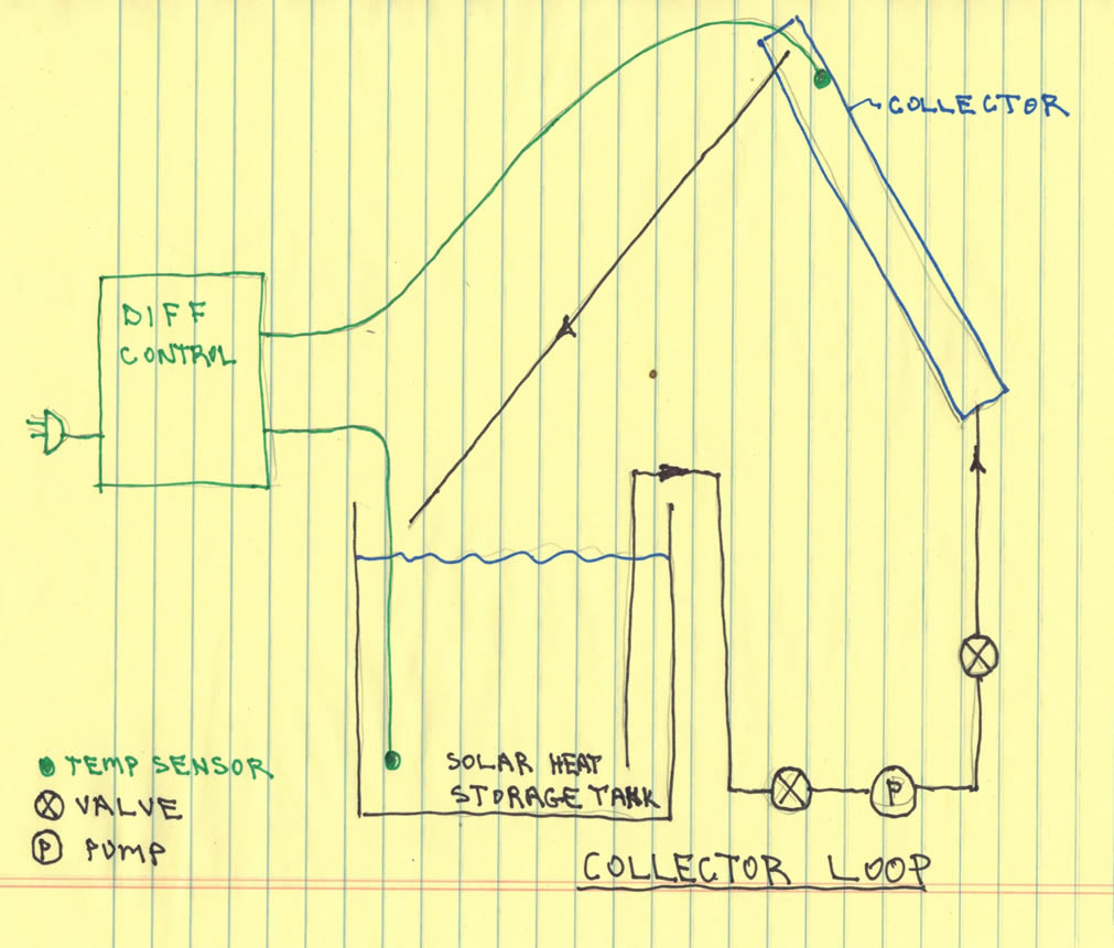
Collector Loop
The collector loop circulates water from the solar tank through the collector to collect solar heat.
A Grundfos 15-58 pump (the P in the diagram) does the pumping.
A standard differential controller (a Caleffi) uses temperature sensors mounted in the collector and in the tank to turn the pump on/off.
When the temperature of the collector exceeds the temperature of the water in the tank by an amount that you set, the controller turns the pump on. When the temperature of the collector drops to where it is only a little warmer than the tank water, the collector turns the pump off. When the pump turns off, the water in the collector drains back down into the solar tank to provide freeze protection.
The valves (X on the diagram) are provided for priming the U-tube that supplies the pump with water and for replacing or servicing the pump.
Most controllers have some additional features that can be handy -- read the manual.
For more detials on the collector loop, see the Collector sections in the TOC...
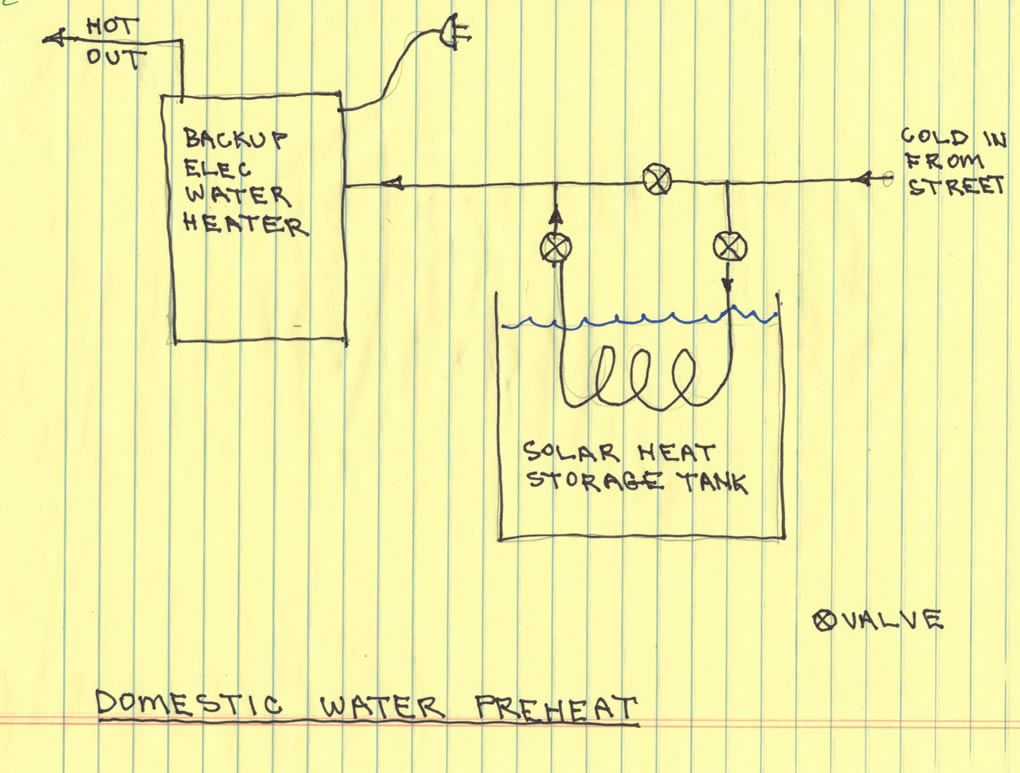
Domestic Water Preheat
The domestic water preheat subsystem preheats the cold water from the well or water main by passing it through a large coil of pipe that is immersed in the solar tank. After the water passes through the solar tank coil, it goes on to a regular electric hot water tank. If the incoming solar heated water is already up to temperature, the electric tank does not turn on. If the incoming water is cooler than the electric tank has been set to, then the electric tank will heat it up the rest of the way.
There are no controls on this part of the system.
The three valves (X on the diagram) provide for bypassing the pipe coil in the solar tank to allow for maintenance. For the solar preheat, the two valves in the vertical lines are opened, and the line in the horizontal pipe is closed.
For more detials on the domestic water preheat, see the domestic water and plumbing sections in the TOC...
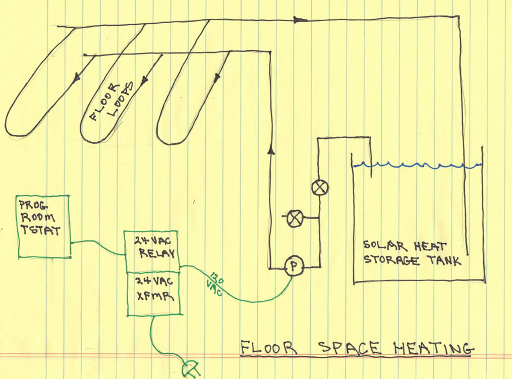
Radiant Floor Heating
The radiant floor heating subsystem circulates hot water from the solar storage tank through the pex loops that are stapled to the bottom of the floor.
A Grundfos 15-58 pump circulates water directly from the solar tank, through the loops, and back to the tank. No heat exchanger is used.
The system is controlled by a regular programmable thermostat that is mounted in the living space. This is the same kind of thermostat that would be used for a forced air furnace.
When the thermostat calls for heat, the closing of the thermostat switch activates a 24 VAC relay that turns the 120VAC pump on. These are all very standard, readily available parts.
The two valves (X on the diagram) provide for priming the pump U-tube with water and for changing the pump if needed.
Each of the three floor loops also has an in line value (not shown) so that the flow in each loop can be controlled separately
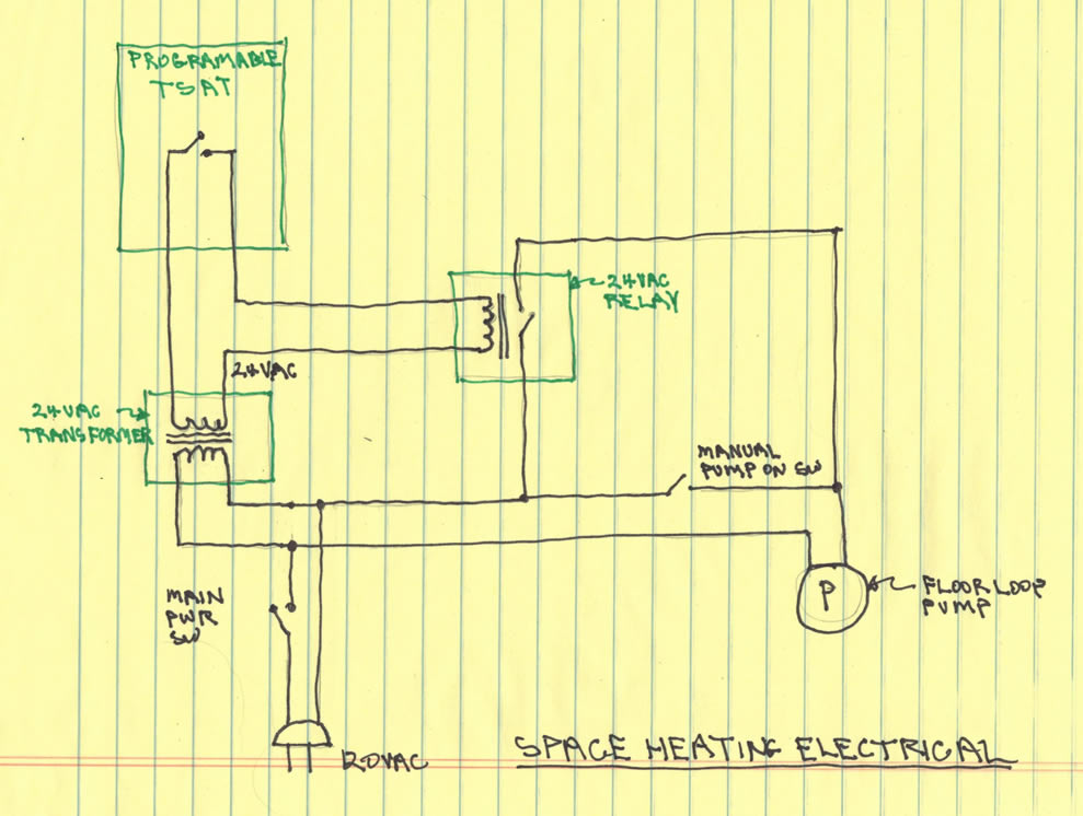
The diagram below shows more detail on the electrical for the floor heating subsystem.
The main power switch turns the whole subsystem off, and the manual pump switch provides for running the pump even if the thermostat is not calling for heat (for troubleshooting).
For more detials on the radiant floor, see the Radiant Floor sections in the TOC...
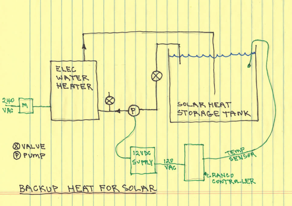
Backup Heating
in the first version of this system, the backup heat for when there was not enough solar was a separate forced air furnace. But, when the furnace went out we decided to add a backup heating source to the solar system in order to avoid replacing the $6000 furnace.
In the new backup heat system, the main solar heat storage tank is kept up to temperature by circulating hot water from a 30 gallon, 3800 watt electric water heater through the main solar tank.
The Ranco heating controller monitors the solar tank temperature, and when it falls below the value you set, the pump is turned on to circulate hot water from the electric water heater into the solar tank.
The pump being used in this system is a TopsFlo pump that runs on 12 VDC -- this is the reason for the 12 volt power supply. It only draws about 15 watts when running. The Ranco controller turns of the pump by cutting the power to the 12 VDC power supply that powers the pump.
For more detials on the backup heat system, see the Backup Heat section in the TOC...
Gary December 21, 2013