
Search
The Renewable Energy site for Do-It-Yourselfers
Pump and Pipe
Sizing for a Solar Water/Space Heating System
| This section covers the sizing of the collector circulation pump and
the pipe diameters for a solar space or water heating system.
The example worked out below is for a drainback system, but the comments
at the end explain what adjustments to make for a closed loop system
with antifreeze.
| |
Disclaimer
I'm not a plumber or solar professional --
I can't even be trusted to
fill the dog's food bowl.
So, use this material at your own risk -- I take no responsibility
whatever for its correctness

As always -- do your homework! |
|
|
|
Overview of Sizing the Plumbing and Pump for Solar Collectors
The basic underlying requirement is that you want a pump and plumbing system
that will push enough heat transfer fluid (typically water) through your solar
collectors to efficiently remove the heat that the sun is depositing in them.
Too little flow, and the collectors will run hotter and less efficiently, too
much flow and you are wasting money on bigger pipes and pumps than the system
needs, and using more pump power than you need to.
The steps involved in the pump and plumbing sizing:
- Calculate the flow that the collectors need
- Measure the vertical distance between the top of the collector and the
tank water level
- Calculate the pressure drop and flow velocity for the plumbing system.
- Pick a pump that provides 1) the flow estimated in step 1, 2) the
vertical lift calculated in step 2, and 3) can handle the pressure drop
calculated in step 3.
The Example
I will use my Solar Shed project as an example. Its shown in detail
here....
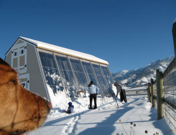
In a nutshell, it has 6 collectors of 40 sqft each. The collectors have
half inch vertical risers tubes (about 9 per collector), and 1 inch top and
bottom manifolds. The collectors are placed side by side with the
manifolds connected together. From a flow point of view, this puts all the
collectors in parallel. All the details are shown
here....
Water is pumped from a storage tank just behind and below the collectors to
the lower manifold on the right most collector.
Water returns from the bank of collectors to the tank via the upper manifold
on the left most collector.
On the Solar Shed, all the plumbing runs are very short, so I'll make the
example a little more realistic by saying that the tank is another 20 ft away
from the collector -- this will lengthen the supply are return pipes and number
of fittings to more realistic values.
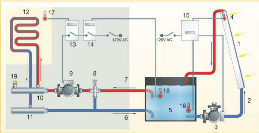
The example covers sizing the pump (3), and the supply and return lines to the
collector (1).
This is a drainback system, meaning that the when the pump is not operating,
all of the fluid in the collector and plumbing system drains back into the
storage tank by gravity. This provides the freeze protection for the
system, and means that plain water without antifreeze can be used.
At the end of the example, I'll briefly cover what the changes would be to do
the pump and pipe sizing for a closed loop system with antifreeze.
Step 1: Calculate the Flow to the Collectors
The collectors need to have sufficient flow to remove the heat from the
collector under sunny conditions. This flow rate can be calculated knowing
the solar heat input to the collector and collector efficiency, but its easier
to just use the manufacturers recommendation. Since my collectors are
homemade, I will use the recommendations for a similar commercial flat plate
collector. Heliodyne makes a series of similar flat plate collectors, and
recommends that the flow rate be between 0.025 and 0.075 gpm per sqft of
collector. You can probably guess from this wide range that its not
critical to hit some particular flow rate -- anywhere in this wide range is OK.
If you want to see the actual
loss in efficiency and heat output from the collector as you reduce flow rate,
look here...
So, lets try for the middle of the range at 0.04 gpm per sqft of collector.
The target flow rate the is:
Target Flow Rate = (240 sqft)(0.04 gpm/sqft) = 9.6 gpm
So, about 10 gpm flow to the whole collector array. Note that the flow
could be anywhere from 6 gpm up to 18 gpm and still be in the recommended range.
Just as a side note, 6 collectors is about the maximum number of collectors
that you want to connect in parallel this way. If too many collectors are
connected in parallel, the flow to all of the collectors will not be even.
For larger numbers of collectors, the collectors can be divided into banks of
parallel connected collectors.
Step 2: Measure the Pump Vertical Head Requirement
For a drainback system, when the sun comes on the collectors, the controller
will turn the pump on, and the pump must be able to pump water all the way up to
the top of the collector to start the flow. In order to make sure the pump
can do this, you must carefully measure the VERTICAL distance between the water
level in the tank, and the top of the collector. If the top of the
collector is 30 ft over and 11 ft up from the tank water level, the number you
want is the 11 ft -- this is the vertical distance from water level to top of
collector. Measure this carefully -- don't eyeball it. Note that you
measure from the water surface level in the tank, not from the pump level.
This requirement at startup to pump water from the tank all the way to the
top of the collector is a tough requirement for pumps, and it will likely be the
main consideration in picking the pump to use.
For the my Solar Shed system, the vertical distance from the water level in
the tank to the top of the collector is 11 feet 3 inches.
So, the pump must be capable of pushing water up at least this vertical
distance. Some margin should be allowed about the vertical distance.
In other words, don't choose a pump that just barely has enough static head to
make the top of the collectors. People vary on how much margin should be
added, but Alan R.ushforth,
who has done a number of drainback systems and has had experience with pumps
that don't quite get the flow started recommends that the pump have a static
head capability that is 20 to 30% greater than the vertical distance from tank
water level to the top of collector. I would use that
recommendation.
So, for the Solar Shed, the minimum pump static head would (11.25ft)(1.25) =
14 ft of static (startup) head.
Once flow is well established, and the return line is running full, the only pressure that the pump has to
overcome is the friction losses in the pipe -- that's what the next step is
about.
Step 3: Calculate the Pressure Drop in the Plumbing
| In this step, we will guess pipe sizes, and
then calculate the total pressure drop through the system for: 1) the
collectors, 2) the supply and return pipes and the fittings in these
pipes, and 3) any valves or other pressure drop causing components.
With the trial pipe sizes, we look up the flow velocity and pressure
drop. If the velocity is too high, or pressure drops larger than a
reasonable pump handle, then we up the pipe diameter and try again. |
Pressure Units
You will find several units used to express pressure drop in pipes and
in pump specs. Here is how to convert between them:
1 psi = 2.3 ft of water = 27.6 in of water =
6894 Pa
1 ft of water = 12 in of water = 0.433 psi = 2985
Pa
|
We will need the lengths of the supply and return pipes, and the number and
type of each fitting and valve. For the Solar Shed, the supply and return
lines are very short, because the tank is right below the collectors. This
is nice, but probably not typical, so I've added another 20 ft to each and a few
extra fittings.
Lets try adding up the system pipe pressure drop with 10 gpm flow and 3/4
inch supply and return pipes. The system uses type M copper pipe (this is
the thinner wall pipe commonly sold at hardware stores).
Adding up the pipe lengths and fittings for the system:
|
Item |
Supply |
Return |
| |
Qty |
Equivalent Length (ft) |
Pressure drop
(psi) |
Qty |
Equivalent Length (ft) |
Pressure
Drop
(psi) |
|
Manifold (1 inch) |
12 |
12 |
0.3 |
12 |
12 |
0.3 |
|
Pipe (3/4 inch) |
28 |
28 |
2.5 |
52 |
52 |
4.6 |
|
Elbows (3/4) |
4 |
8 |
0.7 |
6 |
12 |
1.1 |
|
Couplings (3/4) |
2 |
0 |
0 |
2 |
0 |
0 |
|
Valves (3/4) |
0 |
0 |
0 |
1 |
0 |
0 |
|
Total |
|
|
3.5 |
|
|
6.0 |
Build a little table like the one above to record and sum up the pressure
drop numbers.
Pipe Pressure Losses
Using the numbers from the table above, we will sum up the pressure drops for
the supply and return piping and all of the fittings and valves.
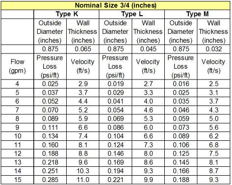
| To get the pressure drop for the 28 ft of 3/4 inch
supply plumbing at the 10 gpm flow rate, look up the loss per foot at 10
gpm for 3/4 inch type M pipe. From the table at the right, this is
0.089 psi per foot of pipe. So, 28 ft would be (28 ft)(0.089
psi/ft) = 2.5 psi. Note also the flow velocity of 6.2 ft/sec.
Velocities between 5 and 8 ft/sec are considered marginally high.
Velocities over 8 ft/sec should not be allowed -- if you get a velocity
over 8 ft/sec the tube diameter is too small.
Do the same lookup for the 1 inch diameter collector manifolds using
the 1 inch diameter pipe chart at the link just below. You should
get 0.025 psi per ft at 10 gpm flow rate -- this gives 0.3 psi for the
manifold drop.
Here are some pressure loss tables for the various types of pipe:
Pressure
drop for copper pipes...
PEX pipe pressure drops...
More PEX pressure drops (very complete)...
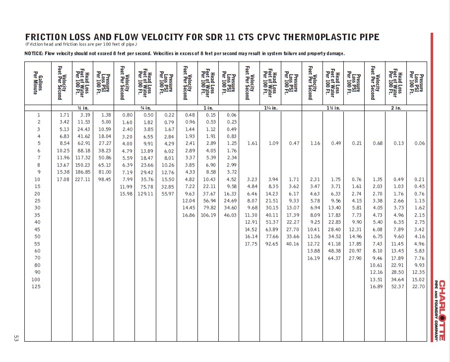
CPVC Household Plumbing Pipe dimensions and pressure drops ..
And,
CPVC
Household Plumbing Pipe dimensions and pressure drops...
(look for the "CTS" tables), or just the CPVC table here...
Industrial CPVC/PVC pipe pressure drops...
Black polyethylene pipe pressure drops...
Note that all of these
different pipe materials have different inside diameters for the same
nominal size pipe. For example, on 3/4 inch pipe, M copper is
0.811 inch ID, household CPVC is about 0.715 inch ID, Industrial CPVC is
0.824 inch ID , PEX is 0.677 inch ID, HPPE (common black poly) is 0.824
inch ID.
Big differences.
So, be sure to use a pressure drop table for the actual type of pipe you
are using. Not being careful about this can throw your pressure
drops off by nearly a factor of 2 in some cases. (1) The CPVC commonly
available in hardware stores is "copper tube sized", meaning the OD
matches copper tubing for the same nominal size -- since the wall
thickness is greater than copper pipe, this makes the ID (and pressure
drops) larger. |
 |
Fitting Pressure Drops
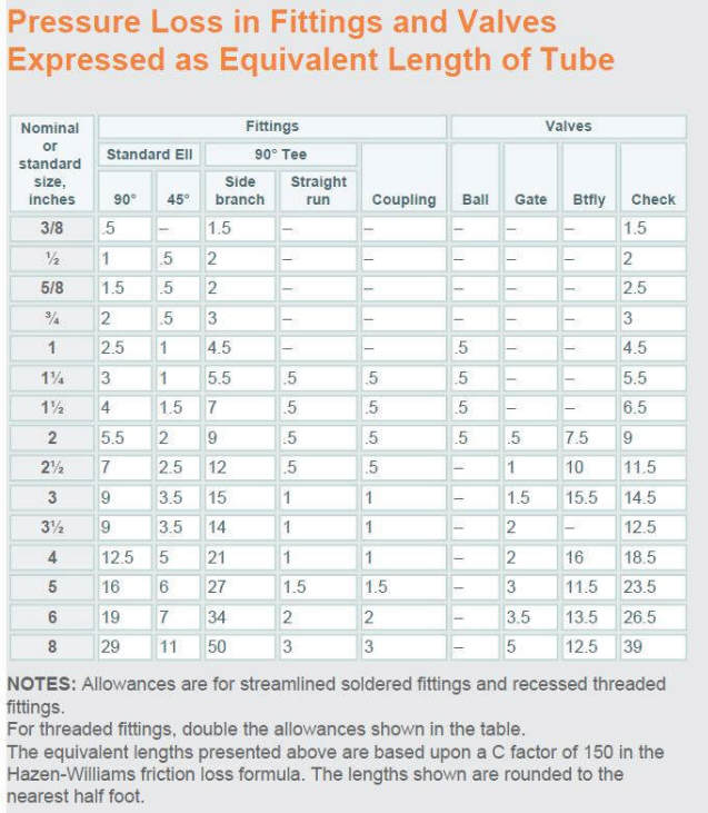
| Use the fitting equivalent length table to
the right to convert the fittings (elbows etc.) into equivalent lengths
of straight pipe. So, for the 4 elbows in the supply line, the
equivalent length of pipe is 2 ft per elbow, or 8 ft total.
Then calculate the pressure drop for this 8 ft the same you did for the
straight pipe sections -- (8 ft)(0.089 psi/ft) = 1.1 psi.
Do the same thing for the couplings and the gate valve -- which turn
out to have 0 equivalent lengths for 3/4 inch pipe.
The fittings equivalent length table is from
www.Copper.org
|
 |
Evaluating the Results
Filling in all the pressure drops in the table, we get a total of 3.5 psi
loss on the supply lines and 6.0 psi loss on the return line. This gives a
total pressure drop of 9.5 psi, or 22 ft of pressure head. We also have a
velocity in the 3/4 inch lines of 6.2 ft/second, which is marginally high.
As we will discover in the pump sizing step (next) this is quite a bit of
pressure loss, and that coupled with relatively high velocity probably means we
should take a look at going up to 1 inch diameter supply and return lines -- so,
lets do that.
If you go up to 1 inch and work the pressure drops in exactly the same way,
but using the 1 inch pipe diameter table, you get this result:
|
Item |
Supply |
Return |
| |
Qty |
Equivalent Length (ft) |
Pressure drop
(psi) |
Qty |
Equivalent Length (ft) |
Pressure
Drop
(psi) |
|
Manifold (1 inch) |
12 |
12 |
0.3 |
12 |
12 |
0.3 |
|
Pipe (1 inch) |
28 |
28 |
0.7 |
52 |
52 |
1.3 |
|
Elbows (1 inch) |
4 |
10 |
0.3 |
6 |
15 |
0.4 |
|
Couplings (1 inch) |
2 |
0 |
0 |
2 |
0 |
0 |
|
Valves (1 inch) |
0 |
0 |
0 |
1 |
0 |
0 |
|
Total |
|
|
1.3 |
|
|
2.0 |
The 1 inch pipe lowers the total pressure drop from 9.5 psi down to 3.3 psi (
7.6 ft head), and it gets our 6.2 ft/sec marginally high velocity down to 3.7
ft/sec. A little bit of extra diameter makes a big difference.
| So, this is likely to be the way to go, but we will see
after the pump sizing. Another option if you did not want to go up to
the 1 inch pipe would be to lower the flow rate down toward the lower
end of the allowed flow rates. Dropping the flow rate down to the
low end of the allowed flow rate would cut the pressure drop in the 3/4
inch pipe down by about half.
|
Side Notes Why are we
ignoring the pressure drop in the collector riser tubes?
The pressure drop through the collector's riser tubes themselves is
small, and can probably be ignored. We have included the collector
manifolds above, and each riser only sees about 0.18 gpm of flow.
If you work through the pressure drop for a 10 ft long, half inch
diameter riser, its only about 0.13 inches of water head. Since
all the risers are in parallel, this is the total pressure drop over the
risers.
On the other hand, If you have a serpentine collector
in which a single length of pipe is wound back and forth through through
the full collector, the pressure drop will be larger and should be
included. Just as an example, if a 25 sqft serpentine collector
uses a single 50 ft length of half inch copper pipe to collect heat, the
the flow will be about (0.04 gpm/sqft)(25 sqft) = 1.0 gpm.
The pressure drop for 50 feet of half inch copper pipe (from the table
below) is about (0.007 psi/ft)(50 ft) = 0.35 psi, or about 10 inches of
water head.
Effective Manifold Length
In the above estimates, I've included only half of the
collector manifold length. The idea is that the flow is steadily
decreasing in the manifolds as each collector takes some of the flow out
of the manifold -- so, including half the length is a rough way of
accounting for this. If you have a lot of loss in the manifolds,
then you might want to do this more accurately by dividing the manifold
up into segments, each with a different flow rate.
Minimum Pipe Diameter
In drainback systems its not considered a good idea to
go to less than 3/4 inch supply and return pipes no mater what the
pressure loss in that smaller diameter pipes may not allow a full
drainback. Supply and return pipes must also be sloped
downward toward the tank, and the runs should be kept as direct as
possible |
Step 4: Pick a Pump
We need to pick a pump that provides:
- A startup vertical head of at least 14 ft determined in step 2.
- A flow rate of around 10 gpm with a plumbing friction loss of 9.5 psi if
we use 3/4 pipe, or 3.3 psi if we go up to 1 inch pipe.
You use pump curves to determine which pumps might meet those criteria.
We will use the pump curve family for the Taco HVAC circulator pumps to pick a
candidate. This series of pumps has been used for lots of solar
applications, but there are many other options
pump
options out there that you could look at...
These are the pump curves for the entire Taco "00" series circulators.
For each pump, the curves show the combination of flow rates and pressure heads
that the pump can produce.
We need a pump that can produce a startup or static head of at least 14 ft.
To find the startup head for a pump, trace its curve over to where it meets the
left vertical access -- this is the startup or static head for the pump.
For example, the 006 pump produces about 8 ft of static head -- not enough for
our 14 ft requirement.
We need a pump that produces about 10 gpm with 22 ft of head (for 3/4 inch
pipe), or 8 ft of head (for 1 inch pipe). To see how each pump does in
meeting this requirement, go vertically up the 10 gpm line, and read to the left
the pressure head that each pump can produce at the 10 gpm flow rate. For
example, a 008 pump can produce almost 8 ft of head at 10 gpm flow rate.
So, for the 3/4 inch pipes, the pumps that might make it are: (we need
14 ft startup head, and 22 ft pressure head at 10 gpm)
011 -- 30 ft of startup head, 23 ft of pressure head at 10 gpm
013 -- 34 ft of startup head, 27 ft of pressure head at 10 gpm
014 -- 22 ft of startup head, 17 ft of pressure head at 10 gpm
The 014 is a bit short on pressure head at 10 gpm, so the flow would fall at
bit below the 10 gpm, but still well within the OK range.
But, these are pretty honking big pumps with high power consumption -- lets
see how things turn out for the 1 inch pipe.
For the 1 inch diameter, the pumps that might make it are: (we need
14 ft of startup head, and 7.6 ft of pressure head at 10 gpm)
007 -- 11 ft of startup head, 7.5 ft of pressure head at 10 gpm
008 -- 15 ft of starup head, 7.8 ft of pressure head at 10 gpm
Some of the larger pumps would also easily meet the flow and pressure
requirements, but would be serious overkill.
The 007 is a bit tempting, but does not quite even make the 11.25 ft of
actual startup head let alone the 14 ft that includes the recommended 25%
margin.
Overall, I like the 008 as a good match on both flow and startup head at a
reasonable power consumption -- so that's why I picked it for the system:)
It has been doing great for 5 years.
If I were to look further into this example with an eye toward lowering the
system cost a bit and the pumping power a bit, I'd have a look at keeping the
3/4 inch pipe, and lowering the flow rate closer to the lower edge of the
acceptable range. This would save a little money on piping and also might
allow changing to a pump that uses less power. The flip side of lowering
flow rate is the the collector will run a little bit hotter, and will not be
quite as efficient. But, it does not look like any of the Taco pumps would
work for this, but a look at Grundfos or other pumps might find a good one.
There are many other pumps out there, and you want to consider things like
price, power consumption, reliability, ... -- not just the that the pump meets
the flow and pressure requirements.
Closed Loop System with Antifreeze
Closed loop system that use antifreeze for freeze protection are always
completely full of fluid, so there is no startup head requirement as there is
for drainback systems.
But, the antifreeze increases viscosity and pipe friction losses, and the
antifreeze has a lower heat capacity, so more antifreeze mix must be circulated
to transfer the same amount of heat out of the collector.
The following rough procedure to cover closed loop systems assumes a 50-50
water glycol antifreeze mix.
To do a closed loop system, use the same procedure as for the drainback
system with these changes.
- Multiply the collector flow rates calculated in step 1 by 1.15 to
account for its lower heat transfer capability -- but I would not go over
the top end 0.075 gpm/sqft.
- Skip the measurement of the vertical rise from tank to collector (step
2).
- Calculate the pressure drops of step 3 just as you would for water.
Then multiply the calculated water flow pressure drop by 1.3 to account for
the increased viscosity of the antifreeze solution.
- Size the pump in the same way you did for the drainback system, but
leave out the startup head requirement, and use the higher flow rates and
pressure drops covered in 1 and 3 just above.
Note that these correction factors (1.15 and 1.3) actually change with
temperature -- the ones I've used are for 140F with a 50/50 mix of glycol
antifreeze and water.
There could be a whole section on using antifreeze, but a couple highlights:
1) use polypropylene glycol, which is non-toxic, 2) use an antifreeze formulated
for solar systems -- it will have additives to keep it from turning into ugly
stuff that can ruin your system, 3) check the pH of the antifreeze every year,
and replace it if the pH is to low (acid) or its otherwise not looking good.
Gary June 25, 2010
Updated Aug 18, to include 25% margin on startup head.