
Search
The Renewable Energy site for Do-It-Yourselfers
ProMaster Camper Van Conversion -- Running Boards
|
While the floor level of the ProMaster van is lower than most vans, it is still a long step up. Most camper conversions include a set of running boards to provide a step about half way up to the floor, and we decided to do the same.
This page shows the installation of the running boards we put in. They are Luverne Omega running boards. We bought them from EuroCamper.com
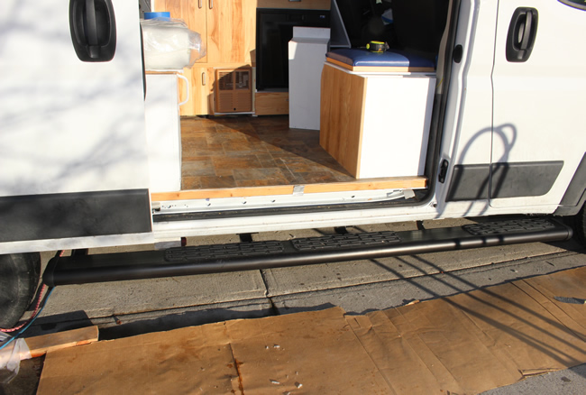
The running boards provide a step up to the floor.
Go back to the main camper van conversion page...
|
|
| |
Important Update
The material on these pages describing our camper van conversion has been moved to our new new site dedicated to efficient RVs and camper vans.
The new site covers all the material here and adds a lot of new material on other camper van conversions, camper van design and build, resources for people converting vans, other efficient camping vehicles, new ideas in efficient RVs and camper van travel hints.
The new site is here...
I'm leaving these pages here as you may have bookmarked them and the Comments section has some good suggestions, but I suggest that you go to the new site -- I won't be updating this material anymore.
Thanks to all the people who read these pages and especially to the people who left comments and suggestions! Feedback on the new site is very much appreciated.
Gary
|
|
Selecting Running Boards
We had panned to use Ionic Running Boards, which appeared to be descent quality at a reasonable price. But, on trying to order them we found that they had stopped selling them because the brackets did not fit the ProMaster correctly and needed a redesign. After waiting months for them to come up with a redesigned set of brackets, we decided to go for the Luverne running boards from EuroCamper.
The Luverne running boards have proved to be sturdy and nice looking, and we are generally happy with them.
Installation
The running boards are extruded aluminum in a heavy gage:
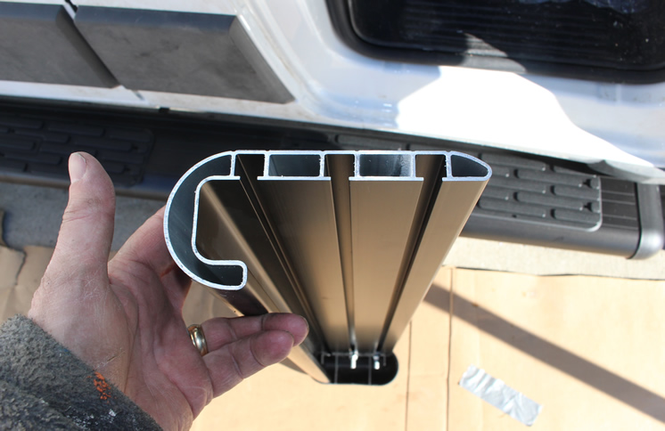
This shows the heavy gage extrusion -- the heads of the attachment bolts slide into the open channels in the extrusion.
I did not get any pictures of it, but square headed bolts slide down two of the open channels. The bolts go through slotted holes in the brackets and are secured by nuts. This works fine and allows for a little adjustment if both the fore and aft position and the inboard-outboard position.
These are the brackets that support the running board and attach to the ProMaster are heavy gage steel.
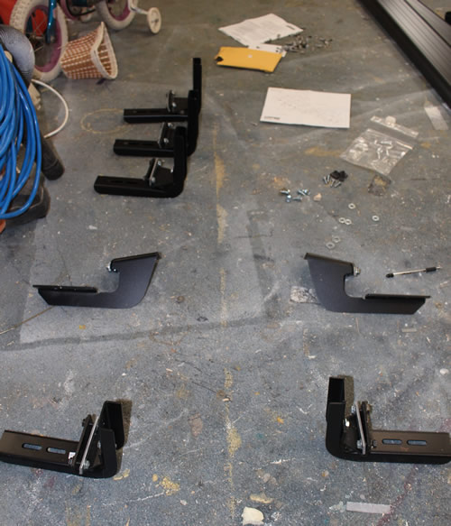
This shows all 7 of the brackets -- the 5 on the left are for the passenger side 96 inch long running board,
and the 2 on the right are for the short drivers side board.
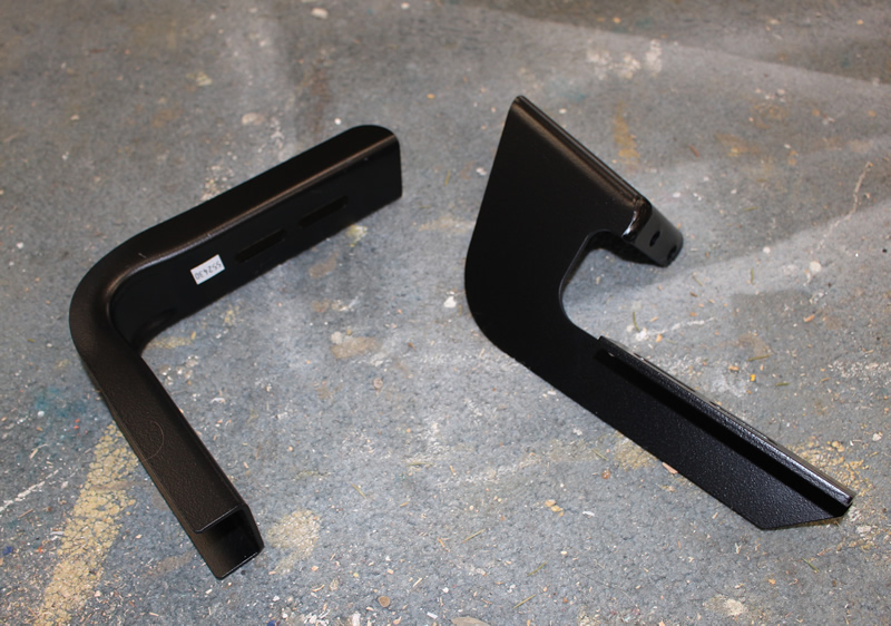
Close up of the forward two brackets.
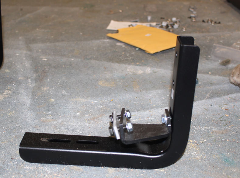
Close up of the one of the aft brackets on the passenger side board. The horz leg of the right angle supports the running board, the vertical leg is screwed to the vertical inside face of the vans rocker panel. The U shaped piece bolts to holes through the pinch weld on the van. See pictures below for how they attach to the van.
You start the install by marking the points on the bottom of the pinch weld of the van for each of the brackets -- these are all measured from the front tire fencer well.
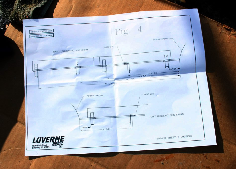
Each bracket attaches to the pinch weld with two 5/16ths bolts -- you start by marking the location of the forward bolt for each bracket by measuring from the front fender well.
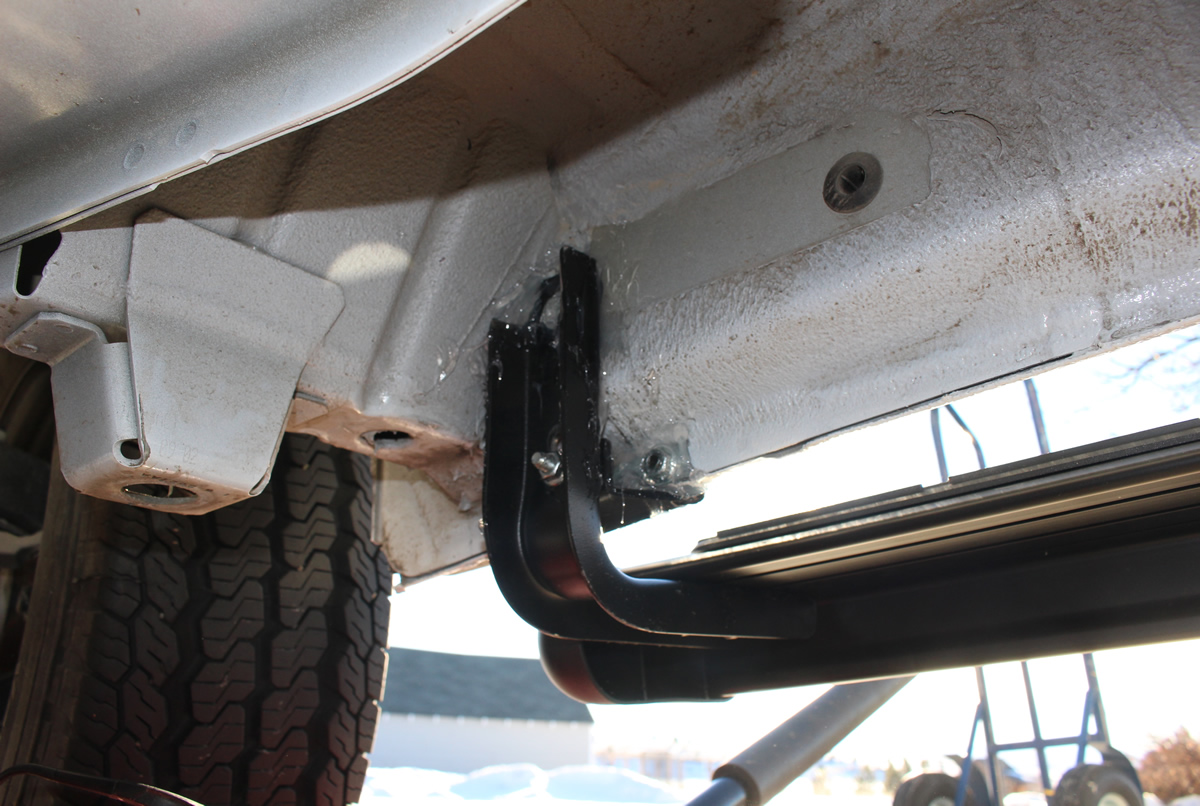
This is the most forward bracket installed. The picture is not that great, but you can see the U shaped spacer between the pinch weld and the bracket attached with the two 5/16th bolts, and the attachment of the vertical leg of the bracket to the inside of the rocker panel -- this attachment is via either a 3/16 sheet metal screw or a nutplate depending on the bracket.
This number one bracket was the most difficult to put in. I had to cut a piece off the top forward corner to make room for the the bracket to fit correctly. In addition, the dimension they provided for locating the forward hole in the pinch weld was not quite right.
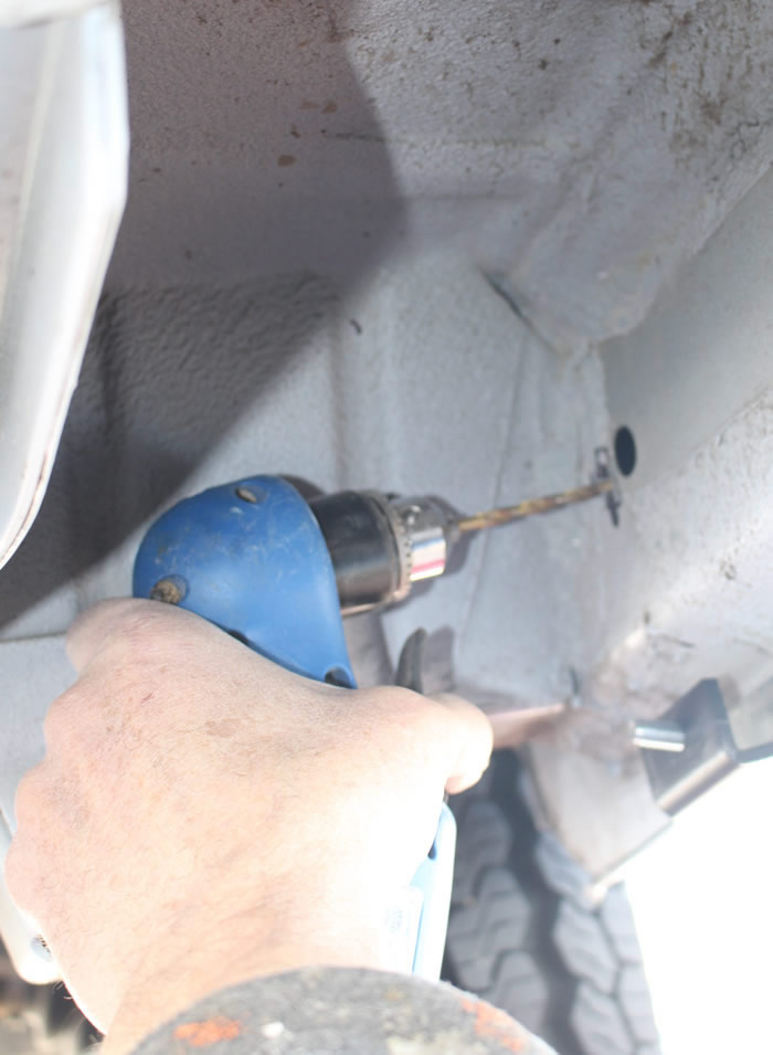
This shows the drilling of the hole in the vertical face of the rocker box panel for the number one bracket. The open hole to the right of the drill is already in the PM with a rubber plug. You drill a hole close to it and slide a U shaped nutplate that they provide into the hold such that the nut in the nutplate lines up with the hole you drill. The vertical leg of the bracket is then screwed to the nutplate with a 1/4 inch bolt. There is not a lot of clearance to drill the hole, and it helps to have a right angle drill like the one in the picture (a Harbor Freight bargain drill).
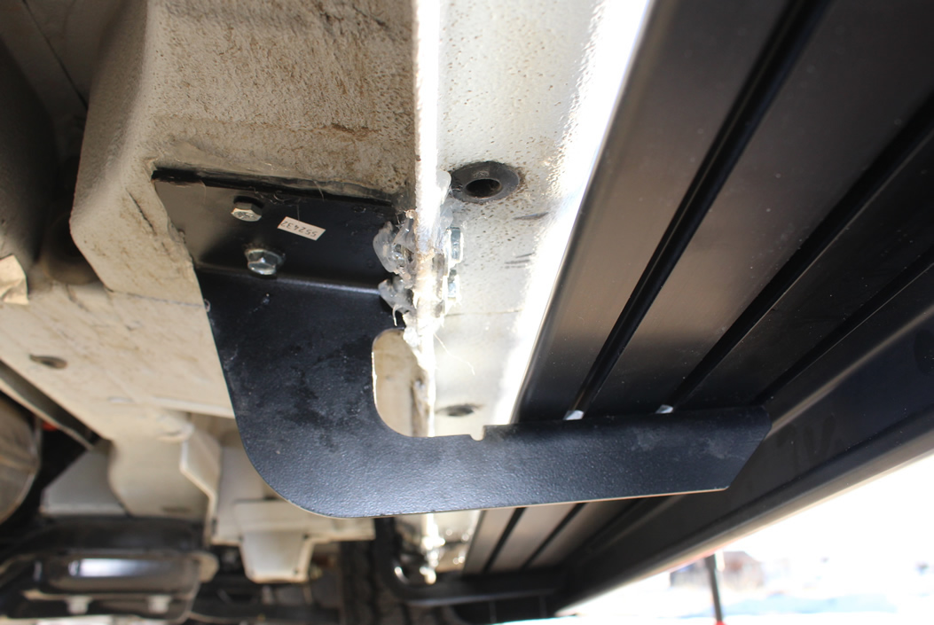
This is the number 2 bracket. Its tho only one that is bolted to the bottom side of the rocker panel. It is the only bracket that cannot be adjusted in height, so the other brackets (which are adjustable in height) are lined up with this bracket.
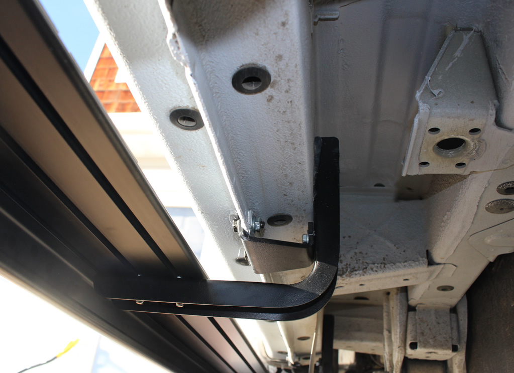
This shows how the aft three brackets on the long running board attach. The heavy gage steel spacer attaches the right angle bracket to the pinch weld using the two 5/16th bolts. The vertical leg of the right angle bracket attaches to the vertical face of the rocker arm panel with one 3/16th sheet metal screw.
Pads
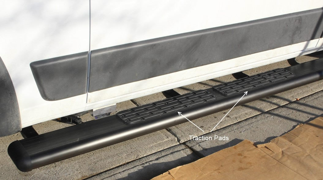
They provide plastic traction pads that you screw to the top of the aluminum running board extrusion with self tapping screws. The long running board comes with three of the pads and you can position them where you like -- e.g. two for the sliding door and one for the passenger door. This seems to work pretty well -- they provide good traction. Time will tell how they hold up.
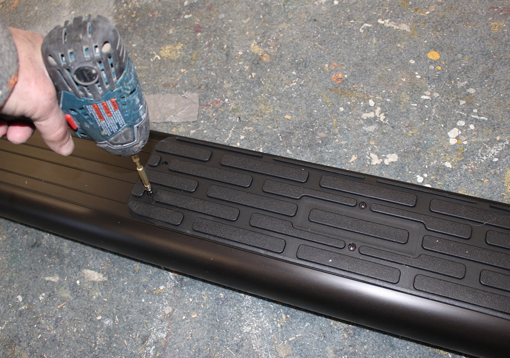
Installing the traction pads with self tapping screws.
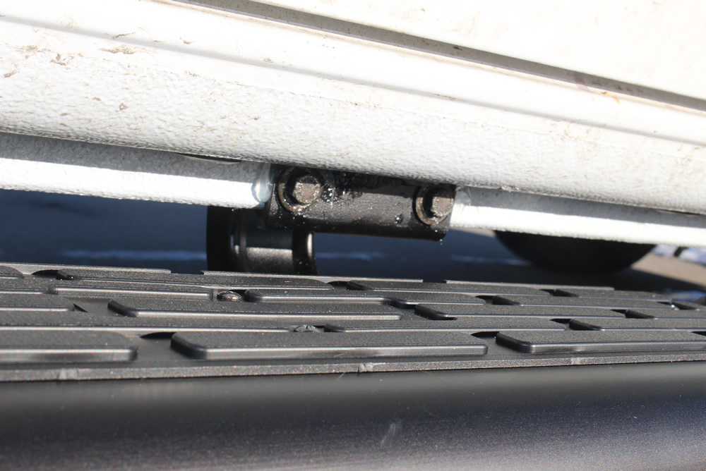
Close up of the traction pads.
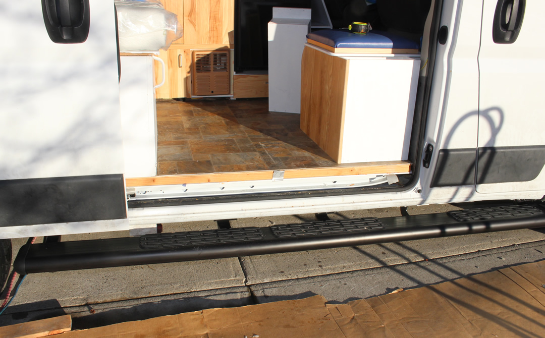
The step height off the ground is just under 14 inches.
The ground clearance below the aluminum step is minimum 10 inches.
The height from the top of the alum step to the finished floor is about 10 inches.
I think this is a pretty good compromise of step height. Even though it would be nice to have the step a little lower when getting into the van, I would not want to give up any more ground clearance. Likewise, the inboard-outboard location seems like a good compromise between providing a good depth of step and not adding too much width to the van.
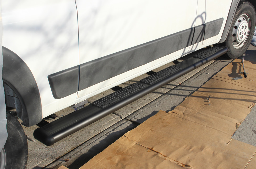
The completed passenger side running board.
Overall Impressions
I think the boards look nice and they feel quite solid. The materials appear to be heavy gage and high quality.
I would rate the quality of the instructions as fair. There was one outright error in the position diagram and a lot of places where the instructions could have been more clear. But, with some head scratching, you can work it out.
Other than the problems with the number one bracket, the installation was relatively straight forward as long as you are OK with drilling quite a few holes in your van :) With the exception of the small mod to bracket 1, all of the parts fit properly and lined up well -- judging from some of the posts on the PM forum this is not always the case.
The design of the brackets and the way they get the running board loads into the van rocker box does not seem as well engineered as it could be, but the end result does seem plenty strong and stiff.
The price coupled with the expensive shipping seem kind of steep to me.
Cost, Weight and Time
The time to install the long passenger side running board was about 5 hours -- the problems with the number 1 bracket probably burned up a couple hours of this.
I have not installed the drivers side board yet, but it will take considerably less time.
| Item |
Cost ($) |
Weight (lb) |
| Cost of the two running boards from EuroCamper |
$409 |
45 lb |
| Shipping |
$110 |
|
| |
|
|
| |
|
|
| |
|
|
| Total |
$519 |
45 lb |
Comments
Comments and Suggestions...
Go back to the main camper van conversion page...
Gary
January 21, 2015
