


|
|
|
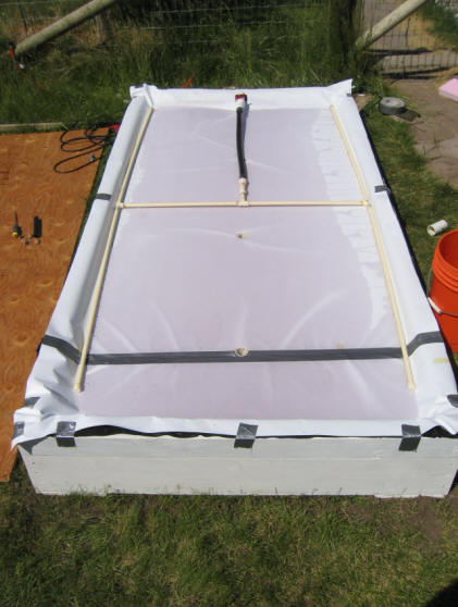
Construction:
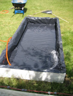
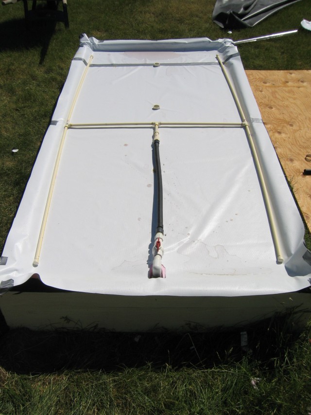
Left - Frame and poly liner. Right - Foamboard with white vinyl sheet over it, and H manifold installed. The pump comes up on the near end of pond and feeds manifold through the flex tube. The pump comes up through an over size hole that has a dam around it to prevent flow back. The oversize hold allows the foamboard to float free, and not be restrained by the pump.
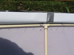
High Flow Rate Conditions:
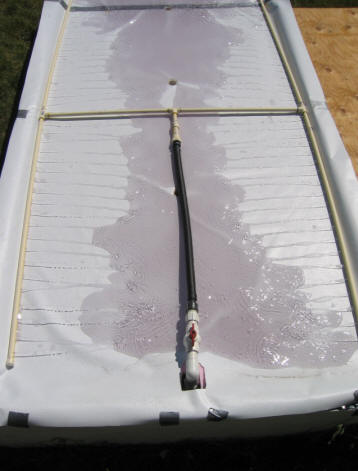
Flow from manifold with pump on full flow (about 9 or 10 gpm). Perhaps a bit to vigorous. Right picture is pretty much equilibrium conditions with full flow and 3 centerline drains. While this is a lot of flow, the good thing is that the flow seems to get everywhere, and keep the water on top of foamboard well mixed. The pump draws 107 watts under these conditions.
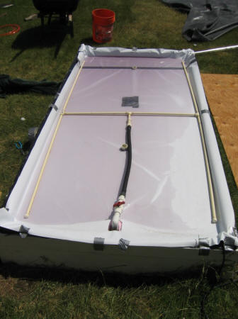
Low Flow Rate Conditions:
Flow turned down to about 2.5 gpm (measured by how long it takes to fill the top of foamboard to 1/2 inch with the outlet tubes pulled up to prevent fluid from exiting). Its hard to see, but the jets coming out of the manifold are about 1 inch long.
Foamboard does not automatically level itself:
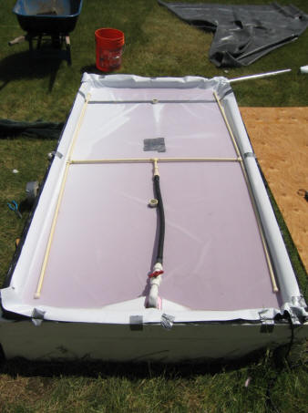
Left picture with most of water in SW corner, right with most of water in NE corner. The foamboard is happy to stay in either one of these conditions -- ie it does not automatically want to level itself.
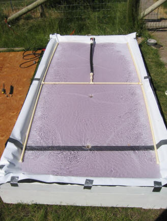
Flow Test with Single Central Exit Sized to Keep Pond about a Half Inch Deep:
Flow Test with exit orifice set to allow about a half to 3/4 inch of water on top the foamboard. The flow rate was 2.5 gpm, and the exit hold was 1 inch in diameter.
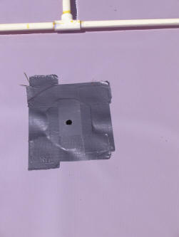
Exit hole (1 inch dia in thin metal plate). The picture makes it look like there might be leakage under the tape, but there isn't. The violet hue comes from ink in the water to be able to see it better.
I left the pond in this state about 2 hours while doing some errands, and no problems or unexpected events. The only not so nice thing is that it does settle into a condition with one corner down or one end down. You can reverse this quite easily by just sending a wave down the pond and exerting slight down pressure on the other end. It is then stable with the other end down.
The ink flow pictures did not turn out very well, but this is what happened:
All done with 2.5 gpm flow and pond depth around 5/8 inch average. Single exit hole fairly near the center.
Ink drop at mid manifold, and near manifold:
Lots of mixing and good progression toward exit hold.
Ink drop at mid manifold and half way between manifold and exit:
Nice flow toward exit.
Ink drop just off end of manifold and near manifold:
Ink initially gets drawn toward manifold -- it may then work its way toward exit hole, but a little hard to tell.
Ink drop near end of box and half way between manifold and centerline:
The ink tends to go round in circles when dropped in any position like this. I don't think there is much flow toward the exit.
Its clear that there are some areas that get poor or no flow toward the center exit. Its harder to tell how much variation there is in flow rate in the area where some flow does occur toward the center.
Seems like these areas would get very hot, and that there is not much happening automatically that would get the flow going just because the areas are overheating?
----
Other Configurations To Try:
1) flow control ridges:
Use the H manifold, and a central drain hole sized to keep the pond about a half inch deep. This is just as described above. Add to this flow control ridges that are about a half inch high, and run from the manifold in a N-S direction to about an inch short of the center line at (say) 8 or10 inch spacing. The idea is that the flow control ridges would force the flow to first go to the center line, and then along the centerline to the exit hole.
There might be 8 or so of the flow control ridges on each side of the centerline running north and south to guide the flow to the centerline.
2) Pump entry in center with edge weir:
Move the pump outlet to the center of foamboard. Add half inch high dams all around the perimeter of the foamboard. The idea would be for the water to flow evenly over the full edge of the foamboard.
I'm a bit skeptical of this working. The flow rate over the dam per inch is so small that it seems like uneven flow will develop from small variations in the dams or foamboard attitude, and that most of the flow will end up exiting over on end or corner???
It does seem like if the flow rate were high enough, the basin on top the foam board would fill up, and the foamboard would not have the tendency to float with one end down like it does with the center exit. That is, it might float more level with this arrangement.
3) Perhaps a manifold running along the foamboard center line in the E-W direction, and dividers that run N-S at (say) 12 inch intervals would work, with a half inch high edge dam all the way around the perimeter of the foamboard? This would effectively divide the top of the foamboard into 8 or so separate ponds that each overflow at the edges separately??
![]()
![]()
![]()


![]()
The "flow dividers" don't allow flow in the E-W direction.
![]() Gary 05/07/07
Gary 05/07/07

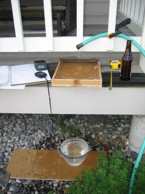
Setup to measure weir flow:
Weir notch is 0.270 inch wide and 3/4 inch deep.
Edge dam is 1 inch deep.
Measured flow rate by timing filling of the pitcher.
The flow out of the weir changes a bit with flow rate -- at higher flow rates it forms an arcing stream out, and at lower flow rates it sticks to the dam as it exits.
![]()
![]()
Gary 05/0708

Contact/About Legal Disclaimer Copyright 2005 by Gary Reysa