


|
|
|
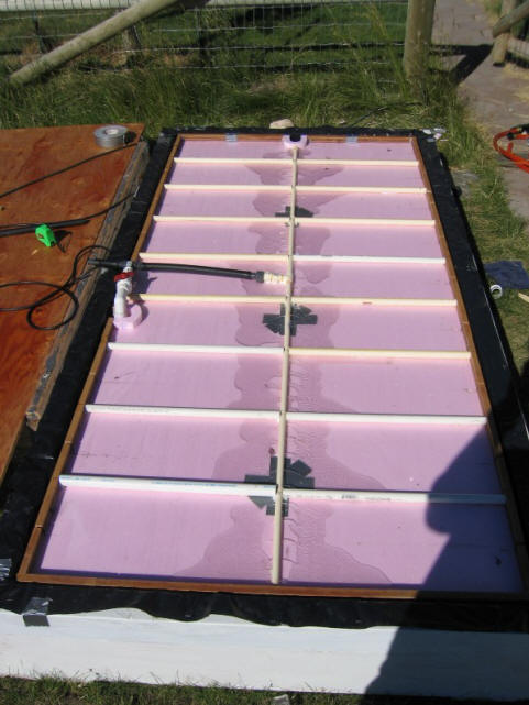
First Test -- Divide surface of foam board up into smaller rectangles:
In this test of flow distribution on top of the floating foam board:
The N and S edge dam configuration is unchanged from last time
The two slots that were added to the W edge dam are taped over.
A pump outlet manifold made from half inch CPVC stretches along the full centerline of the foam board from E to W.
The foam board is divided into 18 smaller rectangles by N-S flow dividers that extend from the edge dams on the N and S edges to the center manifold. Each of the rectangles is feed by 5 small holes in the central manifold that flood the rectangle with 5 small jets of water. The water exits through one edge slot on the N (or S ) side of each rectangle (the edge slots left over from the last test).
This effectively divides the top of the foam board up into 18 separate basin that each floods independently of the rest.
This works really well -- each basin floods nicely. Each basin has very similar water depth in it. There are no deep places on the E or W end, and shallow places at the N-S midline. Initially I made a mistake and only had 2 jets in the W end rectangle, 4 jets in the next 3 to the W, and 5 in the rest. Even with this very uneven flow rate input, it worked fine -- the only symptom being that the depth in the far W rectangles was just a bit shallower -- not too surprising in that they were only getting 40% of the flow of the others.
This setup seems to be more tolerant of variation in the foam board.
With 5 jets in each rectangle, every rectangle runs a flow depth very close to 0.5 inch.
Made a number of little changes and perturbations -- none of these caused any significant change in the flow depths of the rectangles.
Judging the flow with ink drops, it is leisurely, but does make its way to the edge slot. It might be better to have only one large jet into each rectangle, or may two jets (one at E end one at W end). This would tend to keep things stirred up more (I think).
Pic shows center manifold with little 5 little water jets toward each rectangle. In this pic its just starting to flood.
The flow dividers that make the rectangles are left over PVC and CPVC pipe that is help to the foam board by caulk. Too many rectangles.
Second Test -- Make the rectangles larger:
The configuration above works fine, but is a lot of rectangles and flow dividers.
This test basically cuts the number of rectangles in half by taking out every other flow divider.
This did not work out exactly, and one rectangle on the end remains a small one.
The results were nearly identical to above, so, clearly not so many rectangles are needed.
Cycled this a couple times -- no surprises.
I guess the question might be how few rectangles you can get along with?
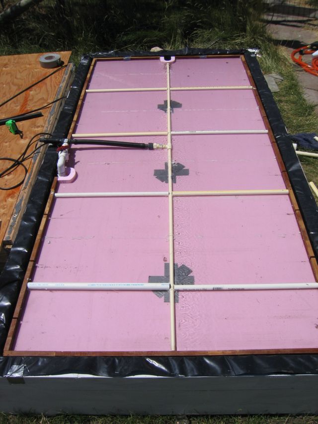
Larger rectangles in fully flooded state. Note the near rectangle is smaller, because I took out every other flow divider to make the large ones, and it did not come out even.
Third Test -- 4 Rectangles and the 4 spout hub:
This configuration divides the foam board up into 4 rectangles (one per quadrant). The four spout hub from the previous test was used to distribute the flow to each rectangle. The flow dividers that formed the rectangles run right up to the 4 spout hub.
The hub gives a nice flow distribution. In each rectangle, 2 flow circles form -- one on each side of the outlet jet. The circle close to the N-S dividers moves very fast -- perhaps 6 seconds for a complete circle. The other (larger circle) on the other side of the jet has about a 20 second circle time -- still quite good.
I think few large jets do a better job of mixing things up and help to prevent dead spots in the flow.
The depth distribution was back to being similar to the earlier tests with no rectangle dividers. That is, deep on the W and E , and shallow on N-S centerline.
Depths:
NW 0.75 inch
W 0.875
N 0.5 + (both sides of flow divider)
NE 0.75
E 0.75 (both sides of flow divider)
SE 0.75+
S 0.5+ (both sides of flow divider)
SW 0.625
I think that 4 rectangles is too few. Maybe 6 would be OK.
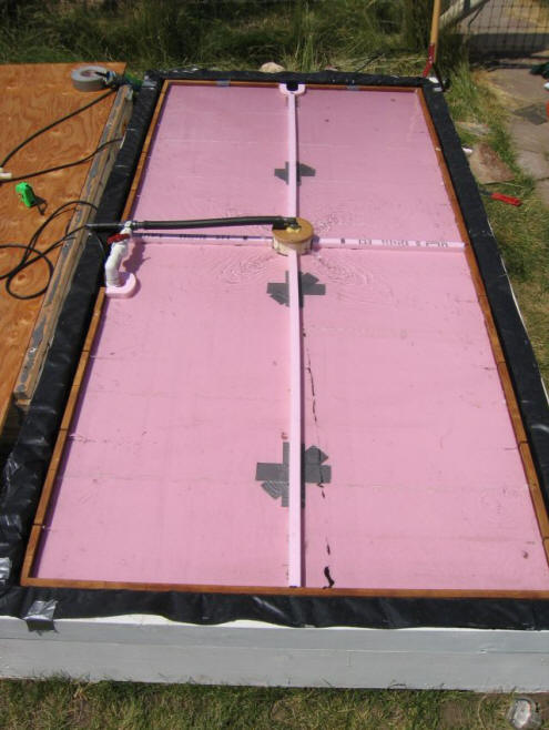
Four rectangles with central four spout hub. This is equilibrium flow.
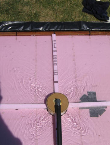
Close-up of hub. Can't see it in the pic, but there are circular flow patterns on each side of each jet (2 circles in each rectangle) -- makes for well mixed flow with no dead spots.
-----
I think that the outer E-W edge dams and the N-S flow dividers (that separate rectangles) could be made from PVC or CPVC with some T's and elbows to make the connections. These go together very fast, and are cheap. The slots could be perhaps be 3 simple saw cuts in each rectangle edge band with a circular saw set to the right depth -- this would make 3 slots at 0.125 wide.
Contact/About Legal Disclaimer Copyright 2005 by Gary Reysa