Search
The Renewable Energy site for Do-It-Yourselfers
Test of a
Thermosyphon Solar Water Heating Collector Made from PEX Tubing
|
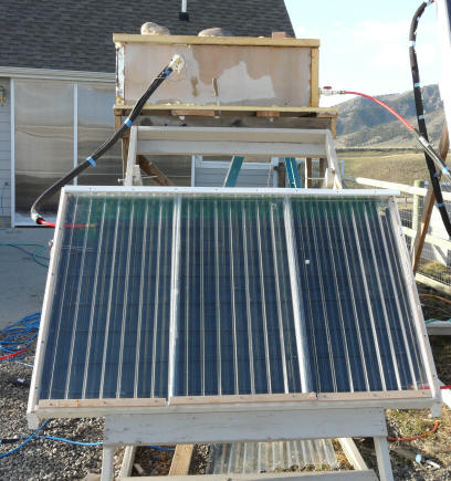
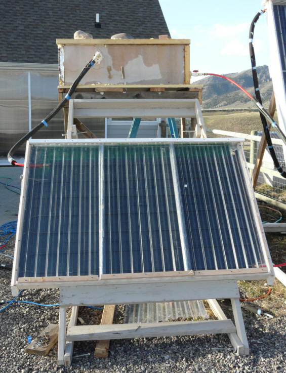
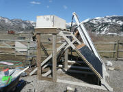
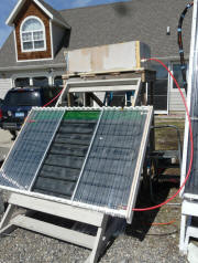
The test collector and the elevated and insulated
heat storage tank.
|
|
This is a test of a
thermosyphon collector. This collector is unusual in that the tubing that
carries the water through the collector is PEX plastic tubing. The
tubing is routed in a serpentine pattern from the the bottom of the collector to
the top. Aluminum fins are used to conduct the solar heat into the tubing.
The collector used for this test was salvaged from
this collector... Basically its the left half of it.
For thermosyphon
systems, the storage tank that is heated by the collector is placed above the
collector. The collector inlet (on the bottom of the collector) is
connected to the bottom of the storage tank. The collector outlet (on top
of the collector) is feed into the tank hear the top.
As sun heats the
water in the collector, it becomes less dense and rises out the top of the
collector and into the tank. This water is replaced by cold water from the
bottom of the tank flowing into the bottom of the collector. As long as
the sun continues to heat the water in the collector, a circulation loop is
setup in which water flows continuously out the bottom of the tank, through the
collector, and then back into the top of the tank.
When the sun goes
off the collector, the water in the collector cools, and circulation no longer
occurs since the water in the collector is more dense than the tank water and
naturally stays in the collector.
So, in this system,
the circulation is all by natural forces -- no pumps needed. And, the
control is automatic -- no controllers needed.
These systems are
very simple and are widely used in some parts of the world.
The things that
motivated the test were:
- There was a
question brought up in the Yahoo Solar Heat discussion group wondering
whether a PEX collector at a normal tilt could adequately control its
temperature if connected in a thermosyphon system. In other words,
will the flow of water through the collector just from thermosyphon forces
keep the collector cool enough to keep the PEX from being destroyed by the
high collector temperatures.
- I have never
worked with thermosyphon collectors and just wanted to learn something them.
There is another similar test of another homemade
collector made from copper tubing with aluminum fins, and using a manifold and
riser design here... The copper collector appears to do a better job
in several ways.
Test Setup
This is a very crude thermosyphon
solar water heating system. It was built just to do this one test, so the
construction was for speed -- not for life or looks -- I know its ugly, but it
can be made to look just fine for real applications.
The collector was salvaged from
this collector that I used last year for heating domestic water.
The collector is a serpentine design,
with each "horizontal" run have a down slope so that the collector will drain in
a drain back system. This might also be helpful for thermosyphoning.
The collector is glazed with a single
layer of SunTuf corrugated polycarbonate glazing. Even though it was put
pack together for this test quickly, it is sealed and insulated as well as the
original collector was -- which was pretty well.
The collector area is 24 square feet.
The storage tank is a galvanized
stock tank -- 45 by 21 by 12 inches tall with rounded ends. The tank is
vented to the atmosphere -- ie not pressurized. For this test, the tank holds 40
gallons.
The tank is insulated all the way
around with 2 inch thick (R13) polyiso insulation.
The bottom of the tank is about 2 ft
above the top of the collector.
The outlet from the tank to the
collector inlet makes use of the tank drain fitting, and is near the bottom of the
tank on the east side.
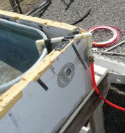
The inlet to the tank from the top of
the collector uses a bulkhead fitting to enter the tank just below the water
line near the top of the tank.
All of the plumbing inside the
collector and from the collector to and from the tank has a slope up toward the
tank. The plumbing is also short and direct with gradual bends.
There are no bubble traps in the plumbing.

Support for tank on back
of existing collector test rack. |
Salvaged absorber and
insulated tank box. |
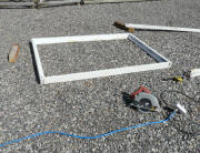
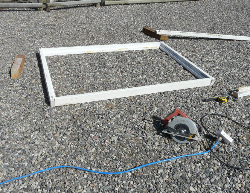
Collector frame salvaged
from old frame. |

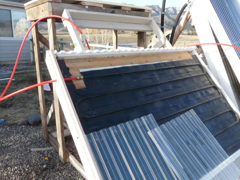
Shows PEX tubes, aluminum
fins, and glazing about to be
installed.
|
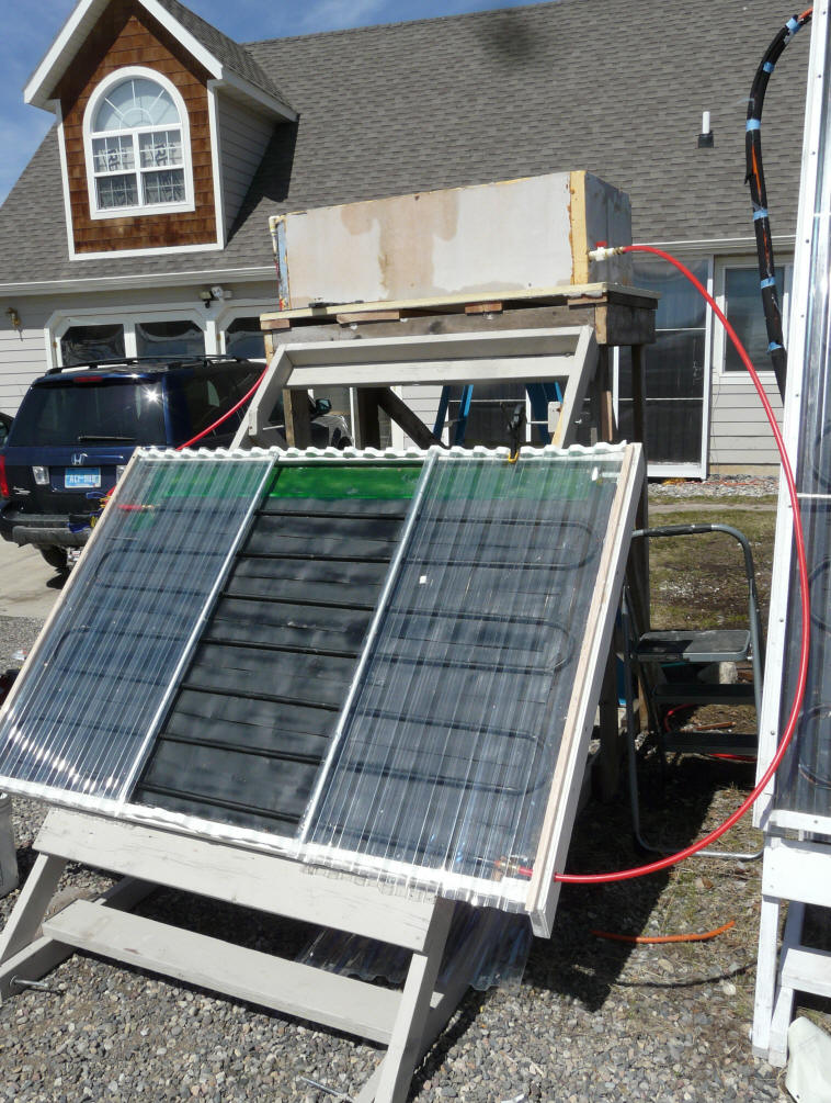
Collect done except for middle
piece of glazing. |
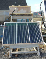
Ready to go |
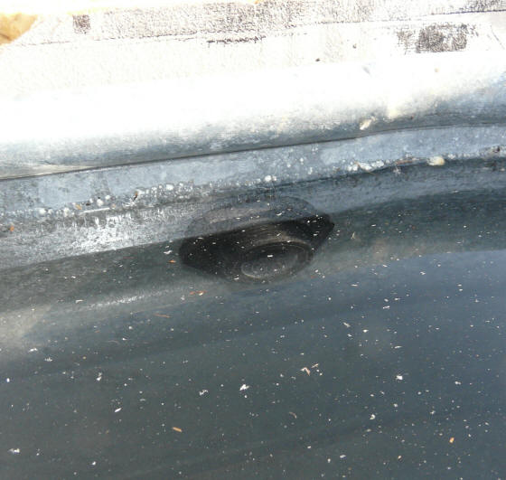
Tank inlet from collector -- just
below
water line. |
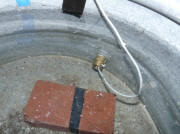
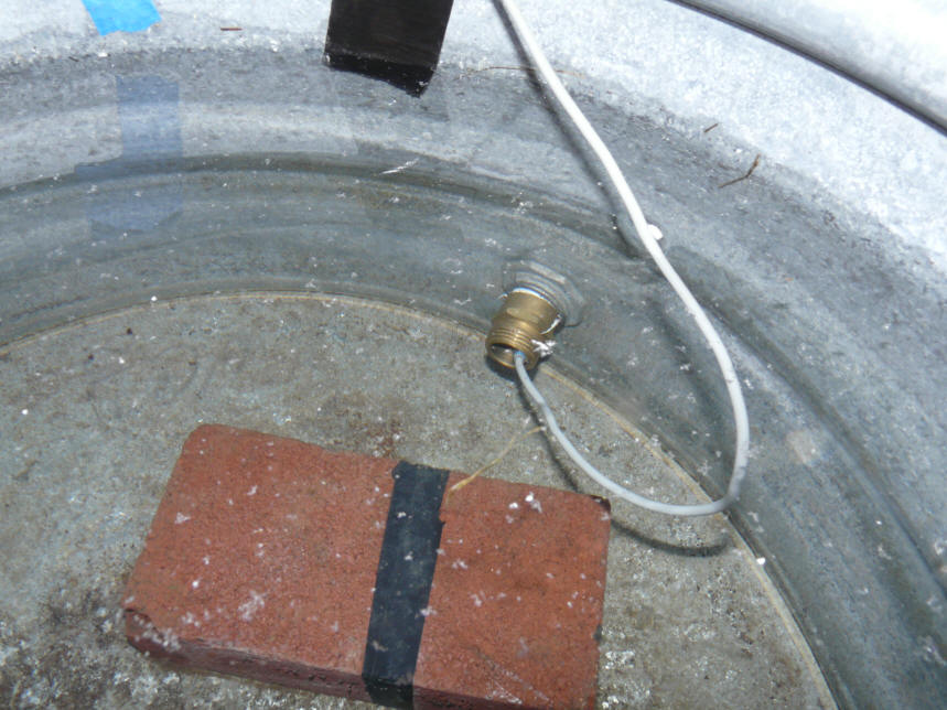
Tank outlet and temperature
sensor. |
| |
|
|
|
The Test:
This is a plot for the full day --
several different tests are included as described below:
Upper red dashed line --
Temperature inside the collector with sensor on the top row aluminum fin
near the PEX tube (F)
Lower red dashed line --
Temperature of water leaving the collector (F)
Blue line -- Temperature of water
entering the collector (F)
It was a very clear day (sun intensity
around the middle of the test on the collector was 950 watts/sq meter as
measured by an Apogee pyranometer).
There was a light wind to somewhat breezy at
times.
Ambient temps from around 50F in
morning to 68F at 1pm.
Solar noon here is about 1:20pm
(daylight saving).
Summary of events that occurred
during the day -- each event is discussed in detial below:
Part 1: 8am to
12:34pm -- The collector running in normal thermosyphon mode.
Part 2: 12:34pm --
the collector is stagnated with fluid in collector tubes, but no flow
through the collector.
At 12:34pm flow through the
collector was stopped by closing the outlet valve on the storage tank.
Part 3: 1:18 pm
-- The collector stagnated with no fluid in the collector tubes.
At 1:18 pm the collector
inlet and outlet lines were disconnected, and the fluid inside the
collector allowed to drain.
At 1:23 pm all the fluid that
would drain on its own was out.
At 1:50 pm the remaining
little bit of fluid was blown out, so collector was completely dry
inside.
Part 1: 8 am to 12:34 pm Collector
running in "normal" thermosyphon mode:
During this time, more sun was
gradually coming on the collector.
Initially, the Collector temperature
rises steadily as it sees increasing sun.
For the most part, the temperature rise of the water going through the collector
was about 10F, and the tank is slowly heating. This is kind of what you
might expect for a thermosyphon collector(?).
At about 11 am, the collector
temperature reaches just over 200F.
From this point on until 12:34 pm
(when flow is shutoff), the behavior is a bit erratic.
The collector temperature bounces
around quite a bit from about 205F down to about 185F. This
was not caused by clouds as there were none.
The collector outlet temperature (as
measured where the water enters the storage tank), goes through wide
fluctuations.
I believe that this fluctuating
behavior has to do with steam forming inside the collector, and the steam
bubbles disrupting or accelerating the flow of water through the collector.
The PEX tube leaving the collector is semi-transparent, and I could observe the steam bubbles going up this
tube.
I could also easily
hear the bubbles as they moved up the tube and entered the tank.
When you look at the steady rise in
collector temperature from early morning until the time the collector
temperature reaches around 200F, it seems likely that this rise would have
continued except for the fact that the boiling of the water limits the
temperature to around the boiling point of water.
The tank is vented to atmosphere and
we are at 5000 ft elevation, so the water boils around 200F.
So, (I think) the boiling of the
water in this vented system holds the temperature to around 200F or a bit more.
Maybe this is OK, but the
unsteadiness of the temperatures and burbling noises did not inspire a lot of
confidence.
So, what would the behavior be if the
system were closed, and were allowed to pressurize as temperatures
increased?
The pressure could raise the boiling
point so water would probably not boil?
But, temperatures would go higher?
It appears to me that the regular
flow through this particular serpentine PEX collector is too low to keep the
temperatures anywhere near the tank temperatures or below 200F.
I did attempt to measure the flow
rate through the collector by injecting a bit of ink with a syringe into the
tank outlet. It took the fastest ink about 4 minutes to start emerging
from the tank inlet. It took about 4 more minutes for the ink to stop
coming out. If you add up all the tubing length its
58 ft. So, a rough average
velocity might be about 58 ft/6 minutes = 9.7 ft/min.
The corresponding flow rate is about
0.098 gpm total flow.
This is only about 0.004 gpm per sqft
of collector -- very low compared to the 0.025 to 0.75 gpm/sqft that some flat
plate collector manufacturers recommend.
This low flow rate probably accounts
for the formation of steam in the collector -- there is apparently not enough
thermosyphon flow rate to keep the collector temperature below boiling.
Part 2: 12:34pm -- Turn off the flow
to the collector
At 12:34, the valve in the
collector inlet line was shut off stopping the flow through the collector.
The collector outlet line remained
connected to the tank inlet.
The result was that the collector
temperature increases some to about 220F, and then appears to stabilize there.
At this point, there is a steady
stream of steam bubbles up the outlet tube with some bubbling out into the tank.
The temperature at the inlet to the
tank from the collector (red) goes up some and bounces around a lot --
presumably due to the steam bubbles, since there is no water flow through the
collector.
Part 3: 1:18pm -- Drain the
collector
At 1:18pm, the line from the tank to
the collector inlet at the bottom of the collector is removed. Water
drains out of the tubing in the collector.
The big drop in collector temperature
just after 1:18 is caused by water from the top part of the tank draining out
through the collector -- so, for a bit the collector is cooled down quite a bit
by the 100F (more or less) tank water flowing through it.
At about 1:23pm the draining appears
to be complete. The collector heats up back up.
At about 1:50pm, I noticed some steam
coming out of the collector inlet, indicating that there was still a bit of
water left in it. This was probably slowing the rate at which the
collector heated before 1:50 -- a little bit of water changing to steam absorbs
a lot of energy.
I disconnected the collector outlet
pipe from the tank, and blew out the remaining bit of water, so after 1:50pm the
tubing inside the collector is dry.
The dry collector heats up fairly
quickly up to about 240F.
Conclusions(?)
Can a dry PEX collector at medium
tilt (45 deg) survive stagnation temperatures?
As the last part of the test with the
dry collector shows, a PEX collector tilted at this 45 degree angle in full sun
will quickly go over what PEX is able to stand. On this relatively cool
day (68F max), the collector reaches 240F,
so on a 100F day it would likely go up to 270F or so. Even 240F is (I think) to hot for PEX to have a descent life.
On the other hand, my
high tilt angle PEX collector appears to be OK (but just).
Could a serpentine PEX collector at
medium tilt protect itself from high temperatures via the thermosyphon flow?
Based on the first part of the day,
I'd be inclined to say no.
The collector with thermosyphon flow
walked right up to boiling temp, and would likely have gone beyond this were it
not for the boiling of the water limiting it to this temperature.
So, at least for this collector, the normal thermosyphon flow does not appear to
take heat out of the collector fast enough to keep the temperatures down below
200F -- even on a cool day, and with not very hot water in the storage tank.
If you think the above
conclusions/explanations are not right or incomplete, or you have any other
thoughts on this, please
let me
know ...
Random Thoughts
I am impressed with how simple these
thermosyphon systems are. No pumps. Completely self regulating.
I guess I knew this in my head, but
its something else to actually put one together and see how very little there is
to the whole system. I would guess that a well designed one would be very
reliable and maintenance free.
An unfortunate thing is that things
get more complex when freeze protection is needed. If antifreeze is needed
for freeze protection than some form of heat exchanger is needed to
transfer heat from the thermosyphoning antifreeze to the potable water being
heated.
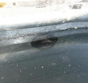
On the first try at this, I had the
outlet line from the collector running up over the edge of the tank, and then
going down and terminating a couple inches under the water line (see just
below). This U tube entry tended to trap bubbles and made for more erratic
operation -- so, I changed to the bulkhead fitting that allows direct entry of
the water with no bubble traps. Thermosyhons are sensitive to plumbing.
Phase 2:
I plan to hook up the copper tube
collector with aluminum fins to the same tank arrangement, and see how well it
does as a thermosyphon collector. This collector has the top and bottom
manifolds with vertical half inch risers configuration rather than the
serpentine arrangement used on the PEX collector. I am guessing it will do
better.
First results on Phase 2 here...
Gary April 20, 2010