First Try At An
Over and Around the Window Collector
The Mother Earth News folks have a strong interest in a solar air heating collector that works in
conjunction with a regular window. This is based on the long term
popularity of the "Heat
Grabber" collector that MEN published a number of years back.
While the Heat Grabber has been popular and works well, it does suffer a bit
from limited collection area and, because it sticks out from the building
making it difficult to use in some situations. So, the MEN folks
are interested in anyone's ideas on how to improve the design.
This is my rough first prototype effort at
a solar air heating collector that could be installed over a regular window.
The idea is to use the existing window to get air into and out of the
collector. This avoids any need to cut holes in the wall for vents.
It also makes it feasible to just install the collector over the winter.
My main objective was to make the collector area large enough to make it
really worthwhile to put the work into building the collector.
So, there is plenty of room for improvement in all aspects of the collector -- how about some ideas?
Some things to keep in mind:
- The window itself is a good solar
collector, so the part of the collector that covers the actual window is
not really very helpful at all in collecting heat -- the window itself
would do about as well. So, in this over window concept, the
collector has to be significantly larger than the window it is covering.- For solar heating, area counts a lot,
so the larger the collector can be made the more heat it will collect,
and the more worthwhile the work invested in the project will be.- Stagnation temperatures can be fairly
high (see below), so the materials used must be able to stand some
exposure to fairly high temperatures -- perhaps up into the 200F area
for a single glazed version.- The vertical orientation selected for
this prototype appears to have some advantages: 1) it does not stick out
from the wall, 2) it may allow the collector to blend into the
house and look better (with some trim work), 3) it allows for a larger
collector area, and 4) vertical collectors benefit from the reflection
from any snow surface in front of the collector.- Air heating collectors work much
better with absorbers that have a large surface area, and that have a
good distribution of air flow over the full area of the absorber.
The material below is a first cut at
trying to do this over window collector, and I'd appreciate any ideas anyone might have on how to
improve it. In some ways, it has some of the same challenges as
David's Flow Organizer, even though it does use a fan.
If you have any ideas that you think might work for improving this design, or
you have an alternative, please
send them in to me, or, you can send them into Mother Earth News.
Directory:
This was put together in a big hurry
as we are packing for a trip that starts tomorrow morning.
The prototype surrounds an existing
window that is about 33 inches by 50 inches, or 12 sqft.
The prototype is 69 inches wide by 94
inches high -- 45 sqft -- so it does provide quite a bit more collection area
than the existing window.
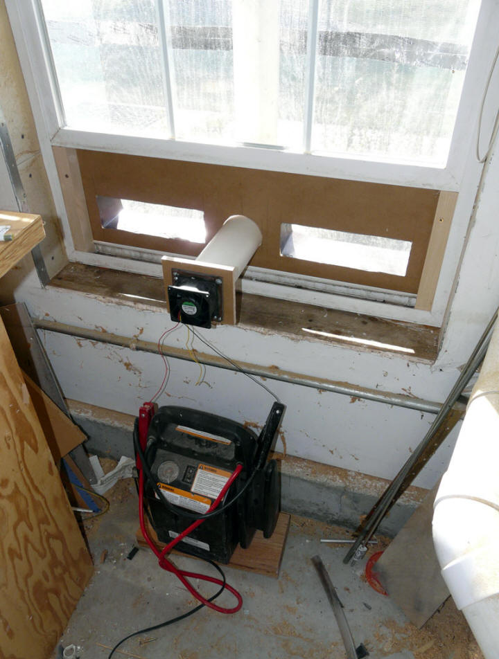
Both supply and return are located at
the bottom of the existing window. You open the window about 7 inches, and
insert the supply/return gadget. My windows only open at the bottom, so
this is about the only way to do it -- if your windows open top and bottom, you
could use the top opening for the return air.
At the top of the collector, there is
a 4 inch diameter hot air collection manifold. The collected hot air goes
down a 3 inch diameter duct from the center of the manifold down to the slot at
the bottom of the window, the 3 inch diameter duct takes a right angle turn into
the room, where a fan mounted on the end of the duct pulls air through the duct
and expels it to the room. So, its a fan forced collector.
The air supply vents for the
collector are also located in the slot at the bottom of the window. There
is one on each side, and each is 3 inches by 10.5 inches. The vents extend
into the collector about 4 inches. The hope here was that the the cool
supply air would follow the cool glazing downward -- as it does on with David's Flow
Organizer. If this works, it eliminates the need for some kind of ducting
system to take the incoming air tot he bottom of the collector.
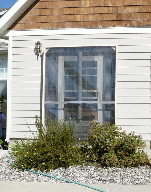
The absorber is black insect screen
(as used on the barn collector) -- I like this kind of absorber for the
window collector because it lets you look out the window, and it also looks
better from the street side, as you can see the siding through the screen.
Window screen can make a good collector absorber...
Note that I was in a rush to get this
done, and did not have anything good to use for glazing. I ended up
piecing together two scraps of vinyl -- this is why the tape splice across the
glazing.
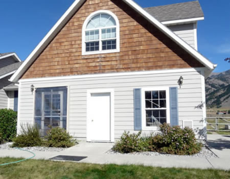
Pictures:
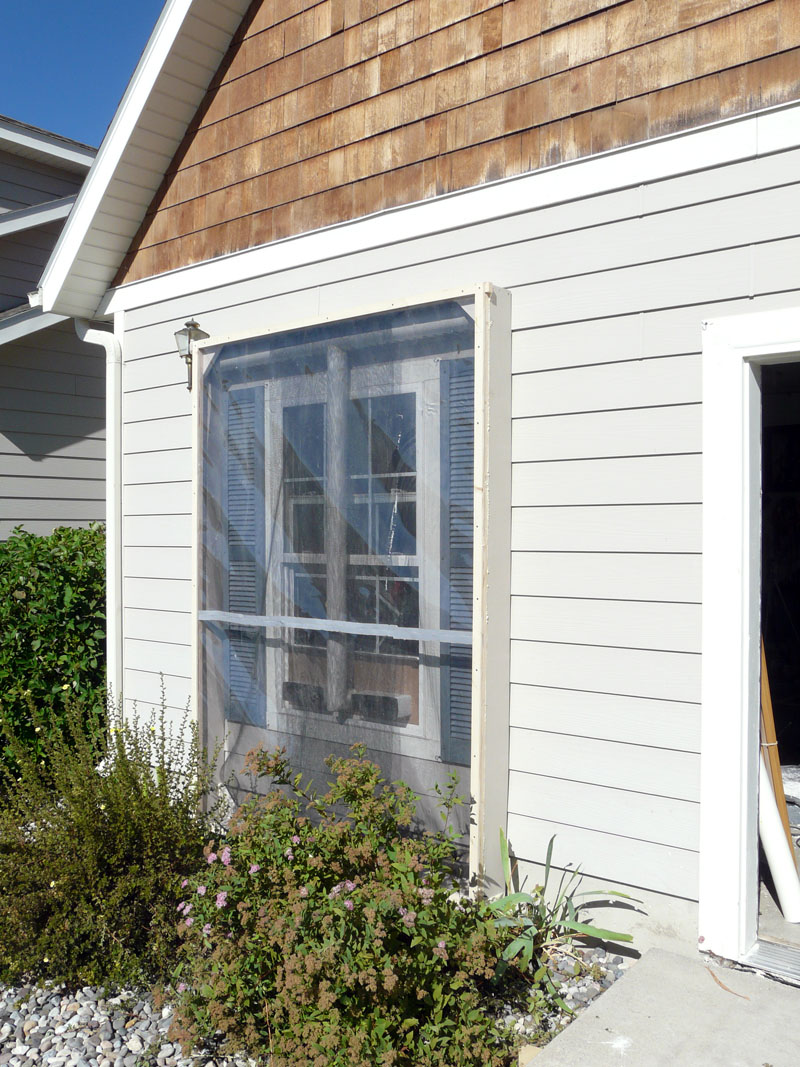
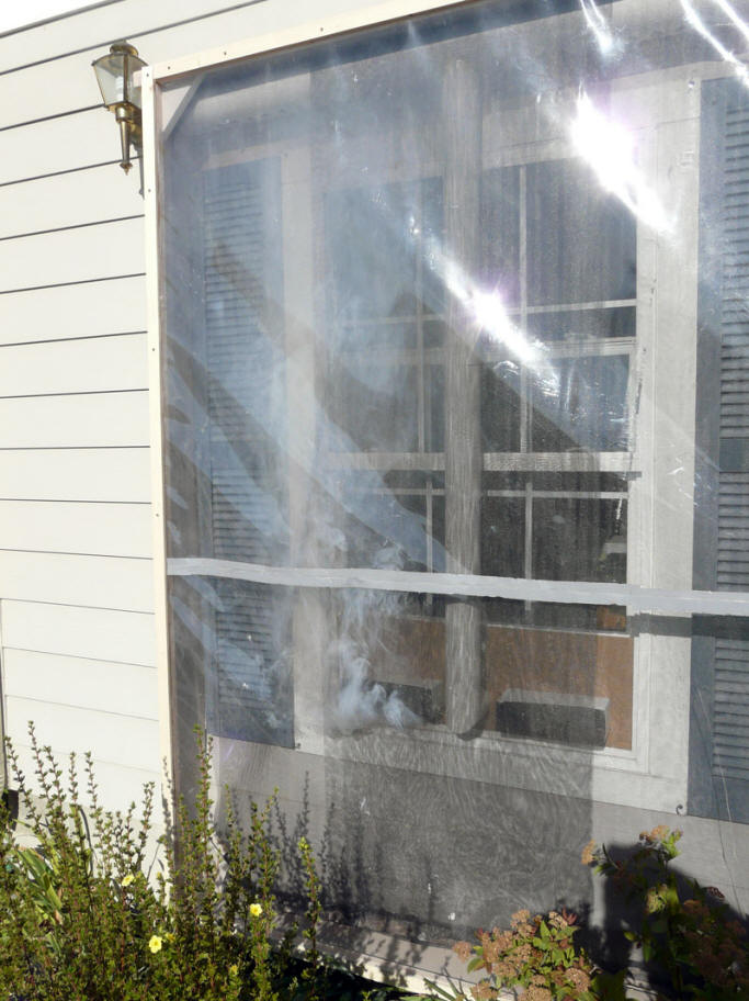
The shutters make this look dark, but
if there were siding, it looks fairly good through
the absorber.
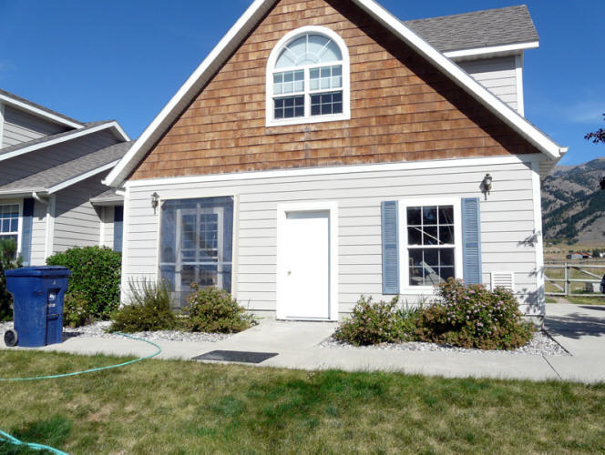
One window with collector, and
identical window without. Note that the collector could be made wider to
add more collector area.
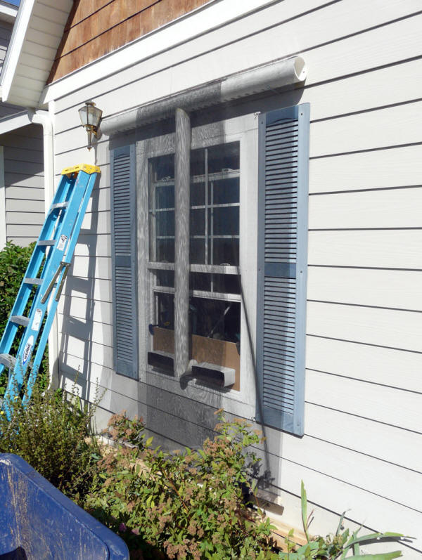
this shows the hot air manifold at
top with many holes in its bottom surface. The 3 inch
hot air duct goes straight down the
from the center of manifold, and then turns into the bottom of
window opening. The fan is just
the other side of the brown board.
The two inlet ducts with the sheet
metal extensions are on either side of the hot air duct.
Idea of the sheet metal extensions is
to encourage the incoming air to get over to the glazing a
and sink down the glazing, and then
be heated and rise up the absorber.
The screen absorber is positioned
such that most of the inlet vent air has to go through the absorber to get out.
The screen is two layers near the
center of collector, and one layer outside -- this is from just overlapping the
48 inch material I had.
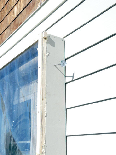
From a seasonal installation point of
view, everything in the picture above can be a single piece that is hung on a
couple lag screws under manifold, or by a couple
"log screws" through the manifold.
This is the inside view.
This could, of course, be made to
look nicer, and the fan need not extend so far into the room.
This is a window in my shop/garage,
so it has no inside trim or finished sill.
The vertical height of the brown
board could also be less.
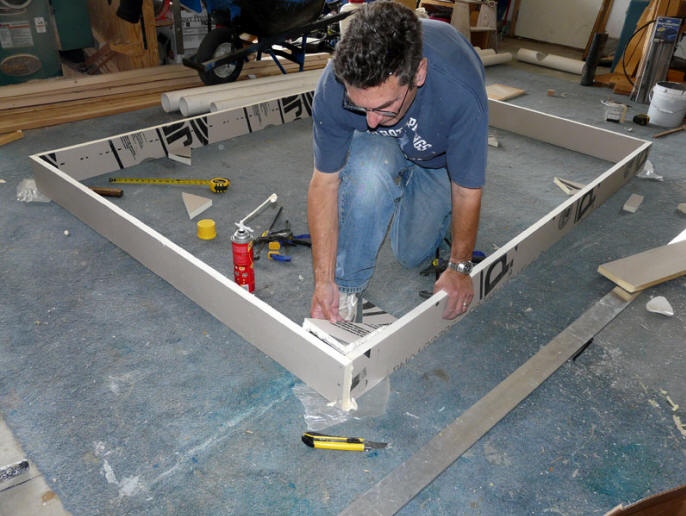
This is the collector outer frame
that supports the glazing.
For the prototype, is just rigid foam
board insulation glued together with Great Stuff.
The Vinyl glazing is mounted in a
wood frame that sits on and is glued to the foam board.
A final version of the collector
would probably want to be made from a more durable material.
This picture shows the wood frame for
the glazing on the foam board.
Another view of the finished
collector and frame.
So, just to recap the concept.
Air enters one of the two inlet
vents, and is directed toward the glazing.
Idea is that this air will make
its way over to the glazing, and because it is cool, and the glazing is even
cooler, it will sink down the glazing (as in the Flow Organizer).
As air flows down the glazing or
when it gets to the bottom of the collector, it gets heated by contact with
the absorber and begins to flow up the absorber and through the absorber.
The two inlet vents are as wide
as possible, and located as far outward as possible to encourage flow across
the whole width of the collector.
Trying to avoid dead air spots
with poor circulation.
As the air flows up the absorber
it must flow through the absorber in order to get to the top hot air
collection manifold. The "flow through" absorber is intended to
improve heat transfer from absorber to air.
Both the pressure gradient
created by the fan, and the buoyancy of the heated air bring it up to the
hot air manifold, where it is whisked away down the 3 inch duct, through the
fan, and into the room.
At least, that's how its supposed to
work.
First Test
I just had time for one quick test
today before we leave tomorrow.
This window in on the west side of
the house, the sun comes directly onto it around 4pm local time.
During the test, the sun was a few
degrees south of the window in azimuth with an elevation of 33 degrees. It
appeared to be quite clear. In other words, good collecting conditions.
I ran the fan for about an hour, and
collected a few inlet and outlet temperatures. Also had a go at measuring
airflow (less successful), and measured stagnation temperature.
Also had a go at a smoke test for
flow visualization.
Representative temperatures:
Tinlet = 78F
Thot air outlet = 118F
So, a 40 F rise.
The stagnation test resulted in
160F in 15 minutes of stagnation -- it might have been increasing very
slowly when I stopped.
Ambient temperature was about 75F
-- possibly a bit higher right at the wall.
Stagnation test sensor placement.
Flow volume.
This little Sunon 12 volt fan is
just the little fan that could. Qualitatively, it appears to put out a
lot of air.
I tried to measure flow rate
three ways -- none completely satisfying:
The fan outlet velocity.
Using the Kestrel wind meter,
the peak of the velocity profile was just over 1600 fpm.
If I assume the average is
1500 fpm, and associate a diameter of 3 inches with the flow, then the
flow rate comes out about 120cfm, or 2.65 cfm pr sqft of collector -- a
lot.
These assumptions on average
velocity and flow area are subject to a lot potential error.
Flow velocity in inlet vents.
I measured the flow velocity
in the inlet vents using the Dwyer Vaneometer. There was lots of
variation, and it appeared that this was due to the wind pushing the
Vinyl glazing in and out. At most, the velocities were around 180
fpm, and at least near nothing.
If one were to use 100 fpm as
an average, the flow rate for the collector would be about 50 cfm.
One factor here is that the
collector frame is not sealed to the house, so there could be a fair bit
of exterior air being pulled in the gaps around the frame.
Garbage bag flow rate
I had a go at trying to do
flow rate by timing the fill time for a 45 gallon plastic garbage bag.
This is the first time I have
tried this, and it would have benefitted with more time to get it set up
right, but we were out of time.
As nearly as we could jury
rig it, the fillings appeared to take about 6 seconds. This works
out to about 60 cfm.
So, hard to say exactly what the
flow rate was, but maybe somewhere between 60 and 100 cfm. It does
look like its up in the 1.5 cfm per sqft, which seems good to me.
I think the whole thing would
benefit from a 4 inch duct and a bigger, slower, quieter 4 inch fan.
So, going out on a limb, the heat
output at this stage appears to be around
(90 cfm)(0.07 lb/ft^3)(118F -
78F) (0.24 BTU/lb-F) = 61 BTU/min, or 3700 BTU/hr -- 82 BTU per hour
per sqft.
While the 3700 BTU per hour is
worthwhile, the 82 BTU/hr-sf does not indicate a killer efficiency --
clearly there is work to do -- see smoke test results below.
Smoke Test:
I had a go at a little smoke
test.
I put a smoke "pill" in the north
inlet duct, and lit it.
See the picture below
On the plus side, the smoke
appears to cover north half of the collector pretty well in the right to
left sense.
On the negative side, the scheme
to try to get the flow to go down the glazing is a total failure. It
appears that all of the smoke goes up.
So, the bottom third of the
collector below the window might as well not be there.
One other observation is that the
collector and fan do a dandy job of filling the shop with smelly smoke.
Questions
Any comments or ideas on how to
improve the collector from either a performance, looks, construction or life
point of view are very welcome.
On the performance side (which was
the main reason for doing the prototype),
Is there a way to encourage
entering air to follow the glazing down and make better use of the bottom of
the collector?
This seems to work well on the
Flow Organizer, but is a dismal failure here -- what am I doing wrong?
Maybe the inlet vents need to go
through openings in the absorber and terminate closer to the glazing?
maybe this scheme does not work
well until the weather is cold enough to cool the glazing down more?
Maybe the pressure gradient
created by the fan overpowers the rest?
Or, should I just go to extending
the inlet ducts down into the lower area, at the cost of more parts and
build complexity?
Any other ideas on how to get
good airflow over the full collector with both supply and return at the
bottom of the window?
It would be nice if there was a
way to make the collector work without a fan at all, but I don't see how?
On the construction and aesthetics
side:
For a collector of this size, the
foam board construction seems doubtful. Not sure what would be a
better frame material choice.
Something that looks more
finished might also help.
The glazing clearly needs to be
better -- maybe a thin, rigid, flat polycarbonate film? Maybe even
twinwall polycarbonate?
While the stagnation temp was
fairly low, I think that when the frame is sealed to the wall, it will go
up, and the PVC ducts probably need to be metal.
Any other suggestions?
It does seem to me that if a house
had 2 or 3 windows that this could be applied to, you could get up toward 100 sf
of collector, and with some efficiency improvements, this could provide some
very useful heat for house.