Solar Hot Water and Space Heating
System With Integrated Boiler
Norm's system uses a large homemade solar heat storage and drain back
tank to provide solar space heating and domestic water heating for his
home in Maine.
The system integrates the solar heating with a boiler that provides the
space and water heating functions when the solar water is not hot
enough.
The tank, plumbing and heat exchangers are very nicely done and
provide a lot of good ideas and construction details.
Its also a good example of getting professional help with some parts
of the system while doing the rest yourself.
Thanks very much to Norm for sending this in!
Norm's full description...
Overview
I acted as my own general contractor and subbed out the pieces to
people with considerable experience in each. The overall design of the
heat distribution system was done by
Northeast Radiant
Technologies of Gardiner, Maine. One facet of their business caters to
DIYers. They also made suggestions on boiler specs that were passed on to
George Phelps of Gilman Plumbing and Heating of Newport, Maine. George
worked with Quincy Hydronic Technology of Portsmouth, New Hampshire. They
are the distributors of Biasi boilers in New England. George's son Rob
installed the boiler and all the related plumbing and controls. The solar
portion of the system was designed and speced by Vaughan Woodruff of
Yankee Solutions
of Pittsfield, Maine. Vaughan worked with both both Gilman and NRT to
ensure that all parts of the system were compatible and complementary. I
built the tank and coils and did all the solar plumbing and control
installation. Vaughan and I installed the solar collectors. The
overall system underwent many changes from the original concept to the final
installed version. I will not go into these here, but would be willing to
discuss with anyone that might be interested.
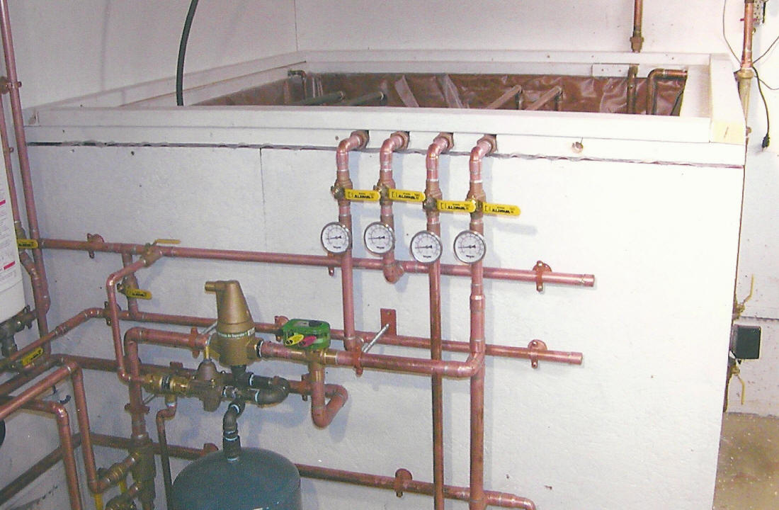
Installed system with boiler at upper left.
This system combines a 550 gallon drainback solar tank combined with a
conventional propane fired boiler (Biasi Riva Plus). The solar tank has
two 60' copper coils to heat domestic hot water and two 90' coils for space
heating. Either part of the system can operate independently of the other
or they can work together. A temperature sensor in the tank is attached to
a relay that cuts power to the boiler any time that the tank temperature is
greater than 125 F. This temperature was arrived at by running a flow test
and determining that the DHW coil in the solar tank will deliver 120 F water
continuously when the tank temperature is 125 F. Also the space heating
coils will deliver essentially 125 F water to the input of the boiler.
Since this is above the normal temperature required for supply to the floor,
there is no need for the boiler to run. Both sets of coils in the solar
tank can be shut off with ball valves, if need be, and then the boiler will
provide DHW and space heating. The input and output of both sets of coils
and the supply and return of the radiant floor have inline thermometers to
provide information on system operation.
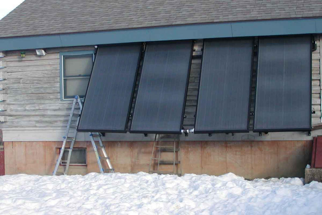
There are four SunEarth
Empire EC-32 collectors, attached to the south wall of our log home, that have
water pumped through them by a three speed
Grundfos Alpha pump. I have the pump set to operate at the middle speed. The
pump is controlled by a Solar Thermal differential controller that senses the
water temperature at the top and bottom of the tank and also the temperature of
the air inside the collectors. The controller is set to allow a maximum
temperature of 140 F inside the tank. If the tank temperature is below 140, the
controller is further set to start the pump any time the collector temperature
is more that 16 degrees above the bottom water temperature. The controller turns
the pump off if the collector temperature falls to within 8 degrees of the tank
water temperature. At this point all the water in the collectors drains back to
the tank. The controller has a safety feature which prevents starting the pump
if the collector temperature is above a preset upper limit to prevent
steam generation. The circulation piping has a Pentair flowmeter which shows
water flow rate while the pump is running and acts a sight glass for tank water
level when the pump is idle.
Click on pictures for full size
The four Sun Earth collectors
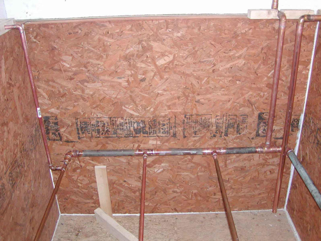
This system is used to provide heated water to two different types of radiant
floor heating systems. One part of the heating system is the conventional Pex
tubing in concrete floor in the basement area of the new addition. The first
floor of the addition uses Warmboard with Pex-Al-Pex under ceramic tile. The
water is circulated through the boiler and the tank heat exchangers by a
variable speed Grundfos pump. The individual zones are regulated by
thermostatically controlled valves. At the present time there are four zones
working and plans are underway to install four more loops in the old part of the
house. These will replace the existing forced hot air system currently in use.
Warmboard radiant floor heating.
System Schematic
(Click on schematic for full size)
System schematic diagram
As shown in the schematic, all items in green are parts of the space heating
side of the system and the items in red are part of the domestic hot water side.
In normal operation valves 2,3,5 and 6 are normally open to allow water to flow
through the respective heat exchangers. Valves 1 and 4 are normally closed.
If for any reason, it is desired to have the boiler operate without any boost
from the solar tank, valves 1 and 4 would be opened and 2,3,5 and 6 would be
closed.
Pump A is part of the boiler installation and pump B is dedicated solely to
pumping water to the solar collectors.
Heat exchanger 1 consists of two 90' coils of 3/4” copper connected in parallel.
Heat exchanger 2 has two 60' coils but otherwise is the same as 1.
The boiler that I used has a primary heat exchanger for space heating and a
secondary for DHW.
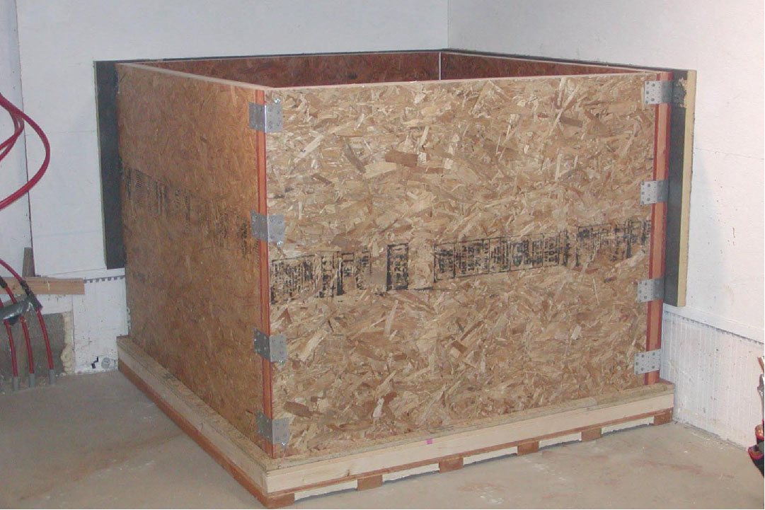
Heat Storage Tank
The tank was sized to accept a liner purchased from Tom Gocze at
American
Solartechnics in Searsport, Maine. The inside dimensions are
55”x55”x48” h. The tank is made from four panels for the side walls, a
platform and a removable cover. The cover is sealed on the edges with 0.5”
round foam insulation to cut down on evaporation loss. The construction of
the tankverticallpanels, platform and cover are described below. panels, platform and cover are described below.
The 550 gallon solar heat storage and drainback tank (click on pictures for full size)
The two exposed vertical panels had another 1.5” of rigid insulation applied
to the outside and a final cover layer of OSB to protect the insulation and
create a mounting surface for the boiler piping and controls. The corner
that the tank was installed in has insulated foundation blocks for the first 18”
of height and a very well insulated wall (R 45)above that. There is also a
floor drain in the corner and the floor is pitched so any leaks should not flood
the basement ( barring catastrophic failure). The drain is also used for
the condensate drain from the boiler.
Tank structure diagram. (click on diagram for full size)
Tank Liner
The liner that I purchased resembles a water bed mattress with an open
top. I did not install the liner until I had put the coil support frame and
coils in the tank first to be sure that everything was going to fit without any
contact with the side walls. I did not want to risk puncturing the liner during
this process. I then removed the coil support frame and the coils and installed
the liner. I made sure there were no sharp edges inside the tank and vacuumed
the inside to remove any unwanted debris. I then placed the liner in the tank
and got inside with my shoes off and smoothed out wrinkles and worked air
bubbles out from between the liner and the tank. The liner has a flap that laps
over the top edge of the tank panels and these were secured temporarily to hold
the liner in place. At this point, I put on a bathing suit and started slowly
filling the tank while making sure that the liner remained in contact with the
tank along the edges and in the corners. I filled the tank to a depth of about
18” and then installed the top rim of the tank to hold the liner in place. This
top rim also has holes to accept the 1/2” copper tubes that support the coil
support frame. I then installed the coil support frame and the heat exchanger
coils.
Nearly finished tank.
A part of the tank liner can be seen on the back inside wall of the tank.
Tank Side Panel Detail
The tank panels are a sandwich of two sheets of 5/8” OSB glued and screwed to
a framework of 1.5” thick strips ripped from 2x4 and 2x6s. One sheet of OSB was
applied to the frame, the voids filled with 1.5” rigid polyisocyanurate and then
the other sheet of OSB was applied. The horizontal strips inside these panels
were placed closer together near the bottom, since this is where the max load
occurs. The actual width of the strips, except on the vertical edges is
not really critical to the overall strength of the panels. I used lag
bolts to fasten the panels together at the corners and thus needed to have
sufficient material for these to grab into. I also used rafter plates that
I bent into ells to further solidify the corners. These panels and corner
connections are no doubt overdesigned but I had most of the material on hand and
the the time needed to precisely calculate the optimum dimensions of the
components couldn't be justified. I did do some basic strength
calculations to ensure that the design was at least adequate.
Tank sidewall panel before insulation and inner OSB face sheet were installed.
Tank Platform
The tank platform is constructed similar to the tank side panels. The major
difference is that 2” insulation was used in the platform instead of 1.5”.
The platform is supported on pressure treated 2x4s to get the OSB up off the
floor. The space between the PT 2x4s has 1” rigid insulation glued in to
create a final insulation thickness of 3” under the tank, the same as the
finished vertical panels. The platform was created larger than the
horizontal dimension of the vertical panels to allow for the extra insulation
and OSB.
Tank platform.
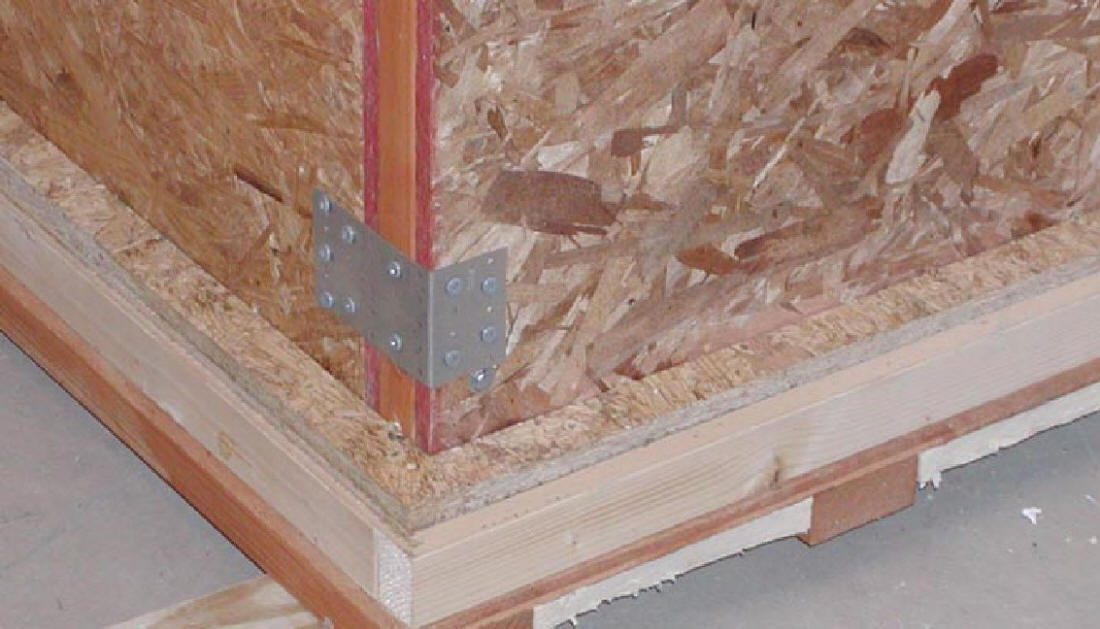
Tank Corners
This picture shows the tank before the outer insulation and OSB were applied.
The vertical panels are in place on the platform. The entire perimeter of
the the vertical panels is captured by a strip of OSB that is glued and screwed
to the top surface of the tank platform. This provides extra blowout
protection ( probably not necessary) and ensures that the vertical panels retain
their proper alignment with the platform (very necessary) while the tank is
maneuvered into its final position. The corners are secured with 5” galvanized
lag bolts that go through the face of one panel into the end of its mating
panel. The head of the bolt is visible just below the corner anchor plate.
The anchor plates are secured with stainless screws in both legs.
Corner reinforcement.
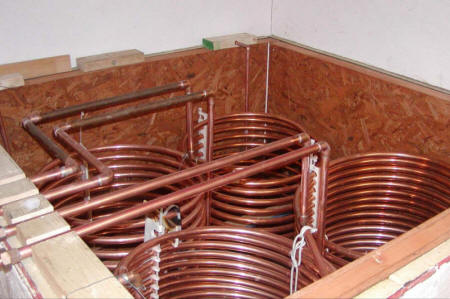
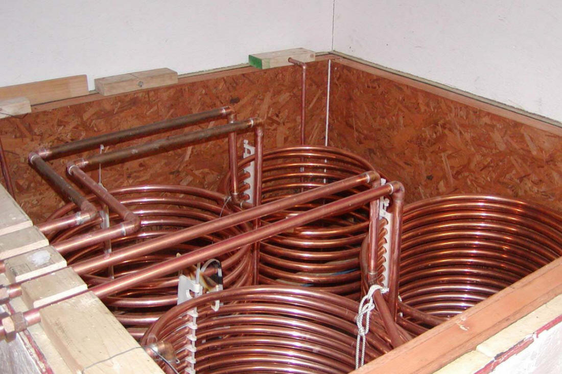
Heat Exchangers
This picture shows the coils in the tank without the liner in place.
This was part of a test run and I wanted to be sure that the liner did not get
damaged. The coils having the wider spacing are for DHW. The right
hand pipe enters the tank above where the liner will eventually fold over the
top edge of the side panels, goes to a point mid way between the coils and goes
to a tee at the bottom of the coils. The water then circulates up through
the coils and exits through the left hand pipe. The other set of coils
operates identically. The only differences are the overall length of the
coils and the change in spacing to accommodate the extra coils. The coils
are supported by a pipe frame to keep them in the top half of the tank.
The coils were assembled in pairs outside the tank and then hoisted into the
tank using a lightweight block and tackle. In order for this to be
possible, the coils were fitted with stiffeners to stabilize them. These
stiffeners are shown closeup just below.
Heat exchanger coils positioned in tank.
In both HX the incoming water is introduced to the coils
thru a Tee that connects the bottoms of the two coils. Therefore 1/2 of the
water being pumped goes thru each coil. The water then comes back together thru
a Tee at the top of the HX and continues on. The space heating HX1 has two 90’
coils of 3/4” copper formed in a coil with a 22” ID. The DHW HX is the same
except the coils are only 60’ long.
With a water temp of 140 F in the tank water being pumped
thru the HX by the boiler circulator exits at nearly 140. Thermodynamically, I
realize this is impossible. The only explanation that I have is that the tank
temp is measured by a probe in the tank that sends a signal to the solar pump
controller and the exit water temp is being measured by an inline analog
thermometer. I am sure that the exit temp is lower than the tank water temp but
my guess is that it is within one to two degrees and the thermometers are not
sensitive enough to tell exactly.
I have tested the DHW HX by running the hot water in my
kitchen sink for 15 to 20 minutes and checking the temps at the end of the run.
Again, with 140 F water in the tank, the inlet water is usually about 50 F and
the exit water temperature is about 135 F. I have a probe in the tank that is
connected to a relay that controls the power supply to the boiler. This relay
shuts off power to the boiler anytime the tank temp is above 125F. This provides
120 F water for DHW and approximately 125 F water for radiant heating. Our
radiant system is designed for water temps below 120 so the boiler doesn’t
really need to run when the tank temp is above 125 F.
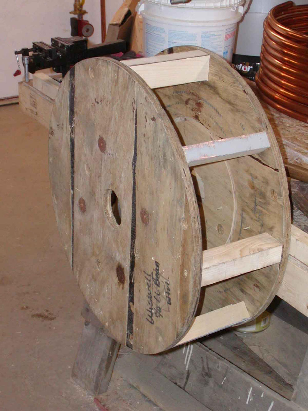
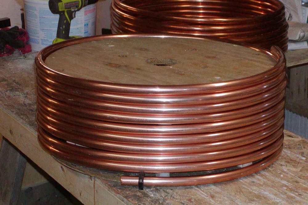
Forming the Heat Exchanger Coils
To form the coils, I created a form using the wooden ends of a large wire
spool. The center of the spool was removed and the ends were cut with a jigsaw
to have the same OD as the desired ID of the coils to be formed. The ends were
then attached together with short pieces of 2x2 to complete the form. Be sure to
make the 2x2's long enough to accommodate the number of coils that you will be
making. I screwed the form to my bench, anchored one end of the coil of tubing
and using a rubber mallet worked the coil to reduce the diameter to match the
diameter of the form. This process requires a little patience but actually goes
quite quickly.
Form for making the heat exchanger coils.
Heat exchanger coil on the form.
Coil Support Frame
This picture shows the support frame in the tank without the liner.
This frame was constructed from a combination of 1” and 1/2” rigid copper pipe.
The horizontal portion of the was sized to keep it and the coils away from the
tank liner to prevent any chafing of the liner. Its purpose is to support
the heat exchanger coils in the upper portion of the tank where the water should
be warmer. The return pipe from the collectors is part of this frame and
supports one corner. The rest of the frame is supported by 1/2” pipe
risers that are capped and inserted into holes in the top rim of the tank walls,
one in each corner. This top rim will be above the liner once it is
installed. Even though this frame will eventually have holes to allow the
water out, it was initially assembled to be watertight. This frame was
pressure tested with air to be sure that there were no leaks in the risers.
Heat exchanger coil support frame.
In the picture , the vertical pipe at the far right is the suction pipe for
sending water out to the collectors. The other vertical pipe close to the
suction is the return pipe from the collectors. This return pipe has a
1/8” hole drilled in it just below the elbow. This serves as a vacuum
breaker to allow the drainback to work properly. The vertical pipe on the
left is used to support one corner of the frame. There are two more of
these pipes in the other two corners. The horizontal pipes in the corner
of the frame furthest from the suction have several 1/4” holes drilled in the
bottom of them to let the return water out. This ensures that the heated
water returning from the collectors is inserted back into the tank as far as
possible from where the water to the collectors is being drawn out. I
drilled enough holes so that the cross-sectional area of the holes was
slightly larger than the area of the return pipe. The holes should be far
enough apart to not compromise the structural integrity of the pipe.
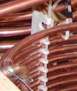
Coil Stiffener
The coil stiffeners/spacers shown were created by heating and compressing
short lengths of 1-1/2” PVC drain pipe. Once a coil spacing was
decided on, the required length of pipe was cut and then heated using an
electric heat gun. A propane torch could also be used but it is easy to
scorch the pipe. Once heated, the pipe is very pliable and can be
flattened using a piece of 2x4 and some clamps on the edge of a bench( or two
pieces of 2x4 and clamps. Be careful to leave one edge with an eye to
accept the zip tie which holds the pipe in the stiffener. Let the pipe
cool back to room temperature and it becomes rigid but in a new shape. It
can then be drilled and cut to create the slots for the pipe. When putting
these on the pipe, I found it easier to start at the top and insert the zip tie
as each loop of the coil was inserted. I created 12 of these and put three
on each coil. This changed the coils from unwieldy 60' or 90' “slinkies”
into something manageable. I created a slide rail above the tank, and
using a light block and tackle was able to lift two connected coils into the
tank. In addition to making the coils manageable, these pieces also hold
the coil loops apart to aid in the heat transfer process.
Heat exchanger coil stiffeners.
Performance
The system as shown has been in operation since April of 2011 and has
performed very well. We had been heating hot water with electricity and
our electric bill has gone down $25 to $35 per month. The overall performance on
the heating side is tougher to gauge due to many changes related to the
installation of this system in conjunction with building a very well insulated
addition to our existing house. The addition is on the north side of a log home.
The R value of the original logs is estimated to be about 7.0. The walls of the
addition have an R value of 45.0. The new construction added about 30% to
the overall floor area and I estimate the heating cost has been reduced about
15%.