
Search
The Renewable Energy site for Do-It-Yourselfers
Rob's Thermosyphon
Solar House Heater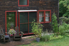
An email and pictures describing Rob's thermosyphon solar house heater.
Thanks very much to Rob for providing
this material.
|
|
Hi Gary-
I just finished up my panel inspired by your Mother Earth News article. I
modified it some to fit in with my 1100 sq ft post and beam house here in
northern New York.
One goal was to use as much "found"
and "used" material as possible. I used five 8'x1"x6" pressure treated decking
boards for the box (new), one 8'x1"x10" pine boards to trim the inlets and
outlets (new), and charcoal window screen to fit (new also.) The rest was
free! I designed the panel around the sizes of used sliding door glass
that had "fogged", giving me roughly 6'x6' total area. the photos will tell
the rest.
Although it's been warm here I've monitored the output and have consistently run
35 to 40 degrees above the outside temperature hitting 130 F as a high so far!
For now the operation is manual, having to open and close the vents, but i hope
to "automate" them with small motors (maybe low volt solar powered on
thermostats) at some time in the future.
The whole thing cost me around $100 and was a lot of fun to build. I
normally burn about 2-3 cords of wood as my sole source of heat and the house is
super insulated and tight. If I save even half a cord a year I will be
thrilled and will have taken a step in the right direction toward being even
greener.
Thank you for your article, website,
and inspiration! keep up the good work and best wishes to you.
sincerely,
Rob
Granville, NY
Rob will answer email
questions, and can be reached here:
Rob Barendse:
barendse AT capital DOT net (change the AT to an @ and DOT to a
period)
More information on how thermosyphon collectors work and some design guidelines.
Pictures from Rob showing the
construction process:
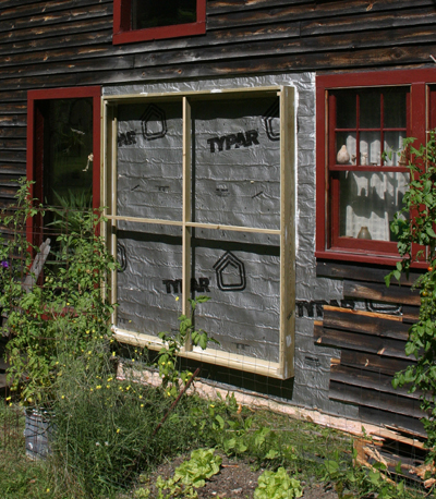
The collector frame made from
pressure treated 1 by 6's.
It looks like Rob carefully removed
the siding in the collector area, and then reinstalled it up to the edge of the
collector when finished.
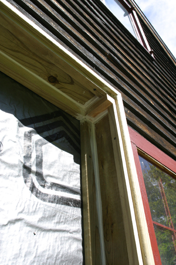
Internals of collector frame.
Note the careful sealing to prevent air leaks.

Cool air from the room flows into the
collector via the lower vents that are visible at the bottom of the collector.
This air flows up through the black
window screen absorber which has been heated by the sun.
The air picks up heat from the
absorber, becomes less dense, and flows up and back out to the room via the
upper vents.
In this picture, the upper vents are
hidden behind the screening.
The circulation is entirely natural,
and is driven only by the buoyancy of the heated air. No fans or power are
needed.
On a sunny winter day, it is typical
to get a heat rise of 60F in the air from the bottom vents to the top vents.
It is a very simple, low cost,
efficient, and elegant solar collector design.
When the sun goes off the collector,
the flow stops automatically.
The collector does tend to backflow
at night, and this can cause heat loss if not stopped.
Rob uses doors on the upper vents,
which he closes each night and opens each morning.
See below for discussion of an
automated means for accomplishing this.
Good sized vents are needed for
thermosyphon collectors.
Rob had to offset the vents from the
middle of the collector due to the post and beam construction of his house.
See the note at the end for more on this.
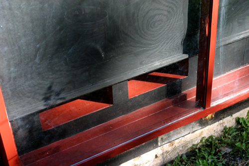
This photo is through the glazing --
very clear.
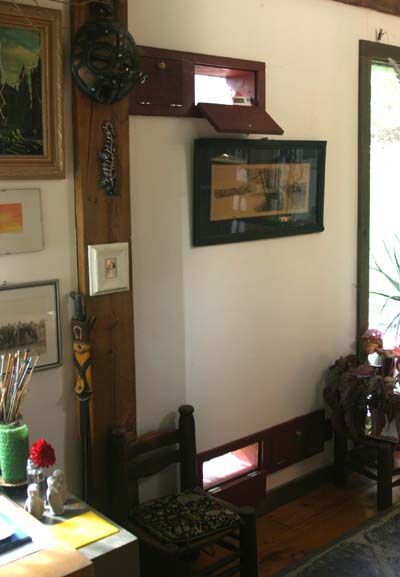
View from the interior showing the
collector entry vents (near the floor), and the collector exit vents (near the
ceiling).
Rob took the picture with one door
open and one door closed for each pair of doors just to show what the doors look
like in each position. Normally all doors would be open during the sunny
periods, and all doors closed when its not sunny.

Close-up of the upper vent doors.
Rob closes these doors manually at
night to prevent backflow through the collector, which would cool the room.
One option for automatic operation
would be to install lightweight plastic film backdraft dampers on the lower
collector vents.
These backdraft dampers would be
backed up by wire mesh so that they can swing freely to allow normal airflow
through the collector, but come against the wire mesh to prevent backflow.
They are similar to the dampers used on
this collector, but are installed in the bottom vent instead of the top
vent. Installing them in the bottom vent hides them from view from the
inside of the room being heated.
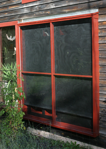
Finished collector with glazing in
place.
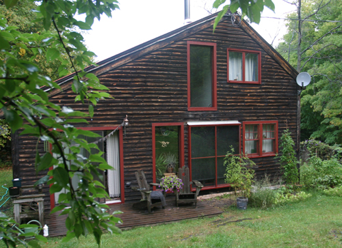
The collector fits in nicely with the
rest of the house.
Note from Rob on the offset vents:
The location
of vents (in and out) was somewhat dictated by the post and beam construction of
the house (8x8's with 2x6's on each side. a big dead space) and aesthetics.
I had considered the offset inlet vents might not work as well but figured the
cooler air would simply "settle" into the bottom and fill the panel. The
top vents are close to centered and the total area for both top and bottom are
equal, though they differ in shape and dimensions, and follow your formula on
sizing. I will monitor this but so far so good! I will live with it
this winter and perhaps make alterations next year if needed.
As far as changes: I registered a new high temp this morning of 144 F. As
the sun is getting lower in the sky and hitting the panel more directly. This
bodes well for winter operation.
I opted to
build the box "flat" on all sides, added a sloping roof, then closed the small
open spaces in with luan. Lastly, I forgot to tell you I covered the whole
back side (against the house) with luan mahogany paneling (used and free!) and
painted it black, to give it a smooth and finished surface. fun stuff!
Rob
Gary Oct 5, 2007