Al's Solar Air
Heating Collector with Hot Water Heating
This page describes Al's new solar air heating collector.
Some
nice features of this collector:
- Its large enough to do some real heating -- people tend to make
collectors too small to be effective for space heating.
- The design of the collector and airflow path look good and
should make for an efficient collector.
- While the collector is mainly an air heater, Al is
experimenting with including some water heating as well.
- The collector looks good!
Thanks very much to Al for sending this material in!
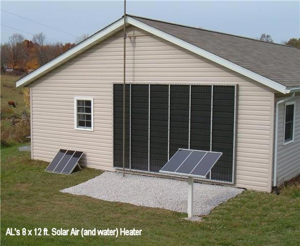
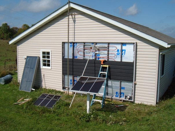
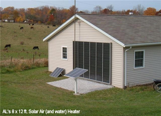
Overview of Al's new air collector along with earlier experiment.
Has a nice, tidy appearance.
Collector Description
I used the higher temperature rated (3/4") Polyisocyanurate insulation board for
the backs. Silicone caulk was used to secure it to all the vertical sides and
'runners' using plenty of roofing nails.
The picture below shows how the
collector bays are built, and the airflow path through the collector from the
inlets in the lower left and right corners to the outlets in the center bays at
the top.
For the right half of the collector, the air enters at the collector inlet just
out of the picture
on the lower right. The air flow up the right most bay, then down the 2nd bay
in, then up the
third bay in, and exits through the round exit vent visible in the center of the
picture.
The left half of the collector works in the same way.
The collector frame is made from pine 2x6's and 2x4's for the middle vertical
'runners'. The middle runners are actually 3" wide though instead of the
full 3.5". I had to rip a half inch off to fit right. I jigsawed out the
'wiggle strips' out of the 2x6 top and bottom and used plenty of Silicon to
seal.
Collector showing the metal absorber partially installed.
The metal is spaced about 3 inches from the insulation board.
The collector glazing is 2 ft wide
corrugated polycarbonate from Lowes. Most Home Depots sell a similar
product called SunTuf. Just be sure to use the polycarbonate corrugated
glazing, as it holds up to the high temperatures well.
Fans and Vents
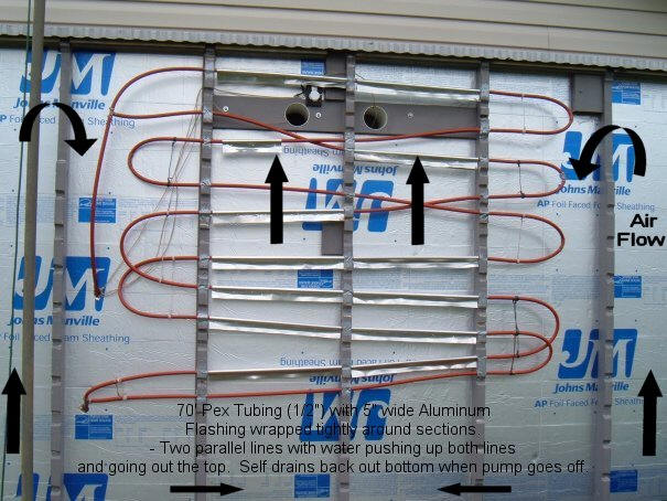
The arrows show the flow direction of the hot air thru the collector, and as it
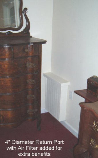
slowly heats the water flowing inside the PEX tubing. There are two 4" diameter
collector inlet ports in each lower corner made from 4" diameter thin-wall drain pipe.
(Not shown in photo)
Therefore, there are essentially TWO separate collectors, the Left and the Right
side.
The wires you see in the photo go to the thermostat above one of the exhaust/output
ports (4" PVC drain pipe) , and to the two fans which are located on the bedroom
wall inside.
Everything is working as planned and I am quite happy with it. Next time I will
be able to make things even better."
Click on pictures for full size
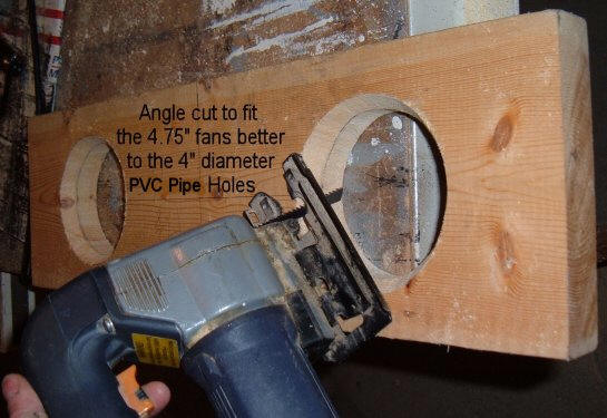
Picture shows the two collector exit
vents with fans in place.
Board on which the fans are installed.
It may of been better to go with somewhat higher flow rate fans than these. But the
reason I went with these weaker fans is, they were very affordable, quiet, and
they use very little power so I can easily run the whole system with my small
12 volt RE-system. In fact, the whole thing could run on just ONE 12V battery and a
30Watt solar panel! Which is nice if the grid goes down for extended periods of
time.
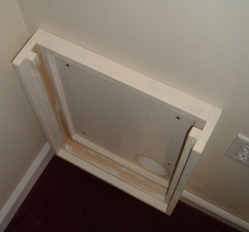
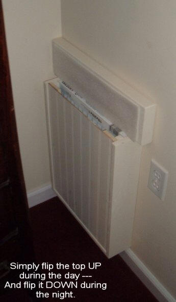
The picture below shows one of the
two collector inlet vents. The vents incorporate a good sized air filter
to reduce dust, and also have a flip down lid to prevent reverse air circulation
at night, which would cool the room.
Click on pictures for full size
Collector inlet vent with front
cover and filter removed.
The actual inlet vent duct is visible
at the lower right.
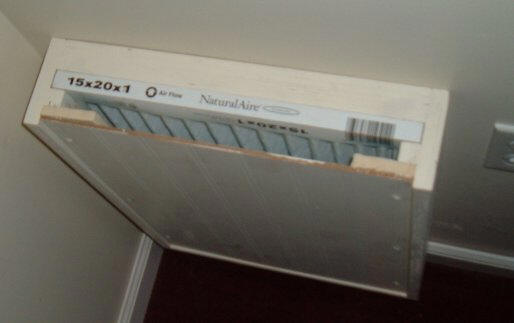
Top view of the collector inlet vent
showing the air filter.
Controls
The fans are automatically controlled by a typical baseboard heat type
thermostat located inside the collector up near one of the 4" output ports. I
can adjust the thermostat (if need be) by taking one of the fans off and
reaching my arm thru the 4" pvc port (thin-wall drain pipe).
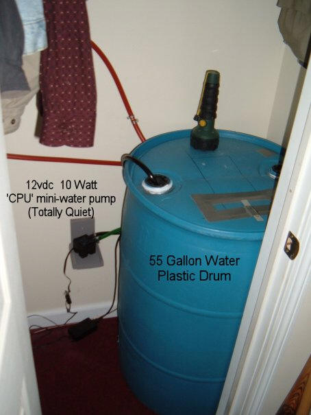
The thermostat goes to a very simple electronic FET-relay circuit (I made)
located in my bedroom closet near the 55gal water drum. The circuit reverses the
'on/off' sequence of the thermostat so the fans can go on and off at the right
times.
The thermostat is set at 70F to turn on the fans. It automatically turns off the
fans after the sun goes down when the thermostat drops below 70F.
This basic control system is not as perfect as real electronic controllers, but
it works fine.
Water Heating
There is about 70' feet of 1/2" PEX
tubing that has two parallel runs which angle downward for good drainage to
avoid freezing when the pump turns off. Water pumps upward from the bottom to
the top, then drains back out the bottom.
I used some Romex wire pieces to squeeze and hold the PEX "U" turns inward.
Click on pictures for full size
This shows the PEX tubing used to
pick up some heat from the air to
heat water in the drum below.
The 55 gallon drum used to store
some of the heat collected during
the day time for use at night.
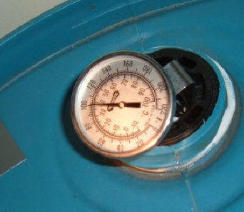
Water heated up to 100F
I primarily made a Solar AIR heater which is what does by FAR the most heating
of the total MASS inside my 740sf apartment/house. But I also thought I would
try my hand at making a basic water heating system inside the Air collector in
order to heat up water in a 55 gallon plastic drum in my bedroom closet so as to
gain some extra BTU's in my bedroom during the night.
I was of course just guessing at many things, and even though it could have been
better I'm sure, I am happy it worked out as planned. I only had room for the
one 55 gallon drum in my tiny closet, so I knew the stored heat would be
limited.
5" wide aluminum flashing was tightly
wrapped around a piece of 5/8" steel rod using 'Channel locks' (Tool) to squeeze into the shape of the PEX. I then just
riveted the aluminum pieces to the PEX with a big bead of Silicone down each one
for better thermal connection as Gary showed. As you can see in the photo, there
is only about 25' feet of the PEX with aluminum wrapped around it. I wish now I
had used even more aluminum around more of the PEX and wider and thicker
aluminum for this, which would have improved the thermal exchange. Probably
copper piping would have been even more effective than PEX in this limited
space. But oh well.
I simply open up the closet door at around 11pm to allow a small heat flow from
the barrel into the bedroom during the night hours.
On decent sunny days the water in the tank gets up to 100 to 110F which helps reduce the
normal heat loss by 5 or 6F by 9am in the morning. The The tank temp drops about
12F over night.
For half sun days, the tank temp only gets to around 82F, but I suspect it is
still helping to reduce heat loss by a couple degrees thru the night hours,
which I will gladly take.
However, I can see now, the water heating system would have been much better if
I had used copper pipes and used more aluminum around it with bigger aluminum
'wings'.
I added a little chlorine bleach to the water in the barrel to keep anything
from growing in it.
Update August 29, 2012:
Al has taken the 55 gallon barrel out of the system because 1) the
benefit of the barrel heat storage was not large, and 2) the closet
space was needed.
I've left in the description because I think it is a technique some may
want to use to get some storage in the system in a simple way, and the
technique Al used seems to work OK.
The 6F drop overnight that Al mentions is worth about 2800 BTU -- as Al
says, this is a relatively small fraction of what the collector produces
(perhaps 10%). More stored heat might be recovered from the barrel
by using a small fan to blow room air over it. More barrels would of course
also increase the stored heat. The same technique might also be used to
preheat domestic water.
Al also reports that he is quite pleased with the system performance, and
about the only change he would make would be to go with fans with a
higher flow rate, as collector temperatures run a bit high. Al
also sees the potential for domestic water preheat using the PEX tubing
already in the collector, and may give this a try down the line.
Gary
Performance
I am very pleased with the Heat this
Solar Collector produces when the sun is out here in the State of Ohio. Over
this Fall season (and I'm sure the Springtime too) there were many days I had to
open a window slightly because it got TOO hot inside my rooms during the
daytime. But this is no big deal, since I like to heat up the total Mass inside
the rooms as much as I can tolerate in order to help keep it warmer thru the
cold nights. (But you have to remember to close the window back!)
How well it does this heating of the
Mass really depends on how much sun there was, how cold it was outside, and how
cold it gets at night. It of course does best with TWO (or more) consecutive
sunny days in a row I noticed.
On a good full sunny day, the heat coming out the fans is 120-145F. This is
also with the Water Heating system on. The Water heating system seems to use up
only a few degrees of this (Flowing Air) heat when it is on at the same time as
the Air heater. So if I know the sun will be good and consistent all day, I
turn on both the Air AND Water heating together. But if the sun is forecast to
be sporadic, I only turn on the Air heater since the Water heating does not work
very well on these type days.
I was also surprisingly pleased that the Air heating collector does fairly well
even on 'Bright gloomy days', though the temps coming out the fans are
significantly less. (65-80F)
It was also interesting that the collector temps react almost instantly with
the sun light strength. Many times the sun peaks out for several seconds and
the fans almost immediately were blowing out 100F air within 5 seconds!! That
was surprising too as it was unexpected. I was watching my hand held thermostat
and the light outside my bedroom window at the same time. It does take a few
seconds more though if the temps outside are around freezing. (30's)
Overall, I am very happy I made this Solar Collector and could not do without it
now. Thanks a million Gary and everyone else!"
Cost
The total cost for materials was
about $500.
Al
Some comments on Al's collector:
- One thing I really like about
this collector is that it looks good. I suppose looks should not be
important to an engineer type, but its a lot more likely that more
collectors will get built if they are not ugly.
- The flow path seems about right
to me both in depth and in length. For these backflow collectors, the
flow path should not be too deep in order to keep the air velocity fairly
high -- this makes for better heat transfer from the absorber to the air.
The flow path length needs to be long enough so that the air has is in the
collector long enough to raise its temp about 50F, so that its useful for
heating. A A path length of 20 ft is about right, and that's about
what Al has. The flow rate should be around 2 cfm per sqft of
collector in order to have enough airflow for good heat transfer and to get
about the right temperature rise. By constraining the air to flow up
and down the collector bays, Al has also avoided the tendency of air flow to
short cut directly between the inlet and outlet, which leaves larger dead
air spaces that make for poor heat transfer from the absorber to the air,
and lower efficiency. I think that this likely to be a collector that
works well.
- I think the idea of trying to
incorporate some heat storage for use at night by adding the 70 ft of PEX
tubing and the water barrel mass is very interesting. I think this
makes sense in the case of Al's collector because the collector at 100 sqft
is more than 10% of his living space area, so there should be some excess
heat to store on sunny days. From the initial readings, it looks like
the water storage system is working, and it will interesting to see more
performance data over time.
Perhaps the same type of system might be used to preheat domestic water?
If you live in a place that gets
freezing weather, you really needs to be careful to incorporate slope in the
tubes so that the drain back to the storage when the pump stops, as Al has
done on his.
- An alternative to the fan
on/off control that Al used would be to use a Thermal
Snap Switch. These come in versions that come on at a set
temperature, and turn off below that temperature, so no rewiring is needed.
A replacement thermostat for an attic vent fan can also be used -- some Home
Depots sell these.
- I think that both the fans and
the inlet and outlet ducts may be a little bit undersized. The airflow
through the collector is about right when the temperature rise from inlet to
outlet is about 50F. If its more than this, than the collector is
running hotter than it needs to, and this will result in higher heat losses
out the glazing and less efficiency. If the temperature rise is much
less than 50F, the moving air coming out of the outlet will feel cool -- it
wants to be around 120 or 130F in order to "feel" like warm air.
Normally, this will mean about 2
cfm per sqft of collector. The fan has to produce this with the
pressure drop through the collector. Note that the advertised rating
for the fan will normally be for essentially zero flow resistance -- it will
not produce this airflow with the flow resistance of the collector and
ducts.
But, its also nice that Al can
run these two small fans on solar electricity with a relatively small PV
panel.
- Collectors like this may
thermosyphon at night and pull cold air into the room. Al handles this
with a flip open lid on the collector inlet vents, and this works fine.
It is also possible to rig automatic backdraft dampers if you want to
automate the process.
- Al experienced quite a bit of paint
odor from the paint used to paint the back of the collector absorber and the
collector housing. This happens once in a while, and (I think) just has to
do with the kind of paint used. Its a bad deal with air collector
because the odor gets circulated into the room being heated.
The steps you can take to reduce the
chances of this:
- Use paint that will not produce
and odor -- I wish I could give some good advice on what types and brands
are safe, but I really don't know. I've not heard of anyone having a
problem with the Rust-Oleum high temperature spray can paint for barbeques, so that
might be a good choice. It seems like a high quality latex paint for
the collector housing should be OK.
It may be that low VOC paints have an advantage.
- Let the paint fully dry and
cure. Set the painted absorber up in the sun so that it heats to a
good high temperature and let it cure for a long time. For an air
collector, I don't think that two or three days is too long. I think that its
important to get the absorber up to the same sort of temperatures it will
operate at.
- If you still get odor when you
turn the collector on, try to rearrange the flow path so that the air
circulates through the collector, but not into the room. This may
require some jury rigging of ducts or absorber and glazing.
If you do experience some odor, I've
not heard of any cases where the odor does not go away over time, and the odor
did go away on Al's collector after about a dozen sunny days.