Search
The Renewable Energy site for Do-It-Yourselfers
Solar Shed -- The
House Heating System
|
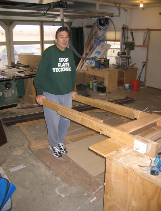
The 240 sqft of solar collectors
mounted on the new garden shed heat the water in the thermal storage tank also
located in the garden shed. To transfer heat to the house, hot water is
pumped from the storage tank via buried pipes to the house. The hot water
coming into the house is distributed to the new radiant floor to heat the house.
The old gas furnace forced air system
is retained for now to cover times when there is not enough solar heat.
|
|
Retrofit of Radiant Floor
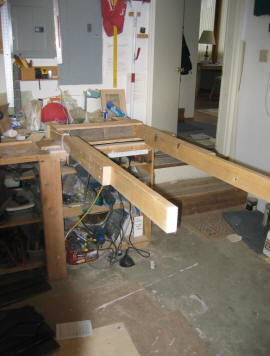
These pictures show the installation
of the new radiant floor. The existing finished floor was removed to get
down to the subfloor. 3/4 inch plywood spacers were installed on the
subfloor with slots every 9 inches to hold the PEX heating tubes. Sheet
aluminum plates are used to spread the heat from the PEX tubes. A floating
finished floor of wood laminate was installed over this.
The radiant floor is an efficient way
to distribute solar collected heat because it can use relatively cool hot water.
Water temperatures as low as 90F will still provide significant floor heating.
Other water heating devices such as radiators require much hotter water to
provide heating. Being able to use cooler water allows the solar
collectors to operate more efficiently.
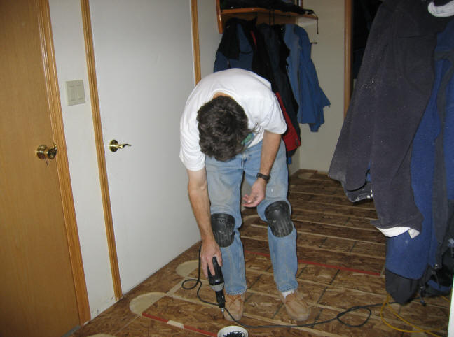
The new 3/4 inch OSB spacers being screwed down to the existing subfloor.
The PEX tubing will run in the gaps between the spacers.
This process raises the level of the
finished floor by about 3/4 inch, and may require a little trimming of the
bottoms of some doors.
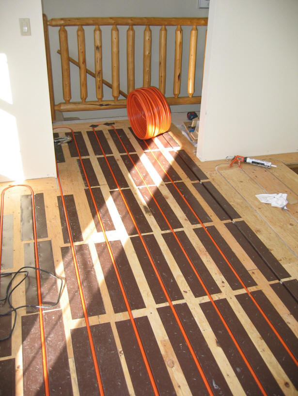
This shows the aluminum heat spreader plates and the PEX tubing installed in the
grooves between spacers. The PEX tubing is PEX-AL-PEX -- this is PEX
tubing with a middle layer of aluminum. I used PEX-AL-PEX because it has a
lower coefficient of expansion than PEX, and because it is easier to work with
than PEX. It also conducts heat slightly better than PEX. A
bead of silicone caulk is placed in the aluminum heat spreader groove before the
PEX-AL-PEX is pushed into the groove -- this is to improve the thermal
connection between the PEX and the heat spreader.
The PEX-AL-PEX is half inch ID. The half inch seems to work pretty well.
It does not raise the floor too much. Most of my loops are from a bit over
200 ft up to about 250 ft. This seems to be working out OK -- with a flow
rate around 0.6 gpm, the temperature drop from the start of loop to the end of
loop with 100F water is about 10F, and the pressure drops over these size loops
can be handled with modest sized circulation pumps.
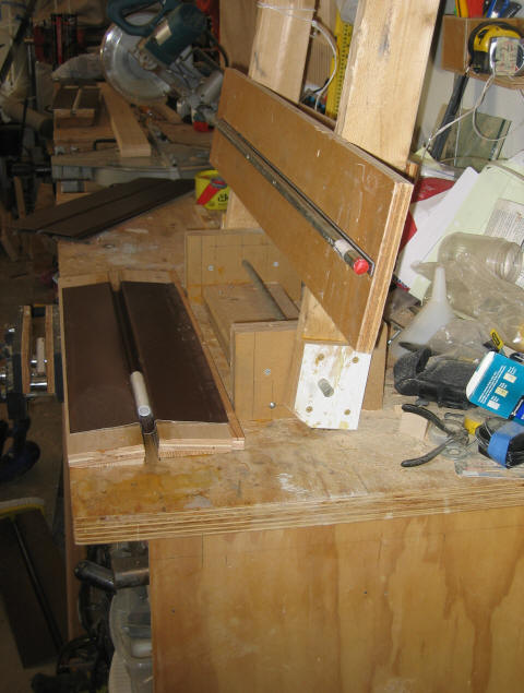
This home made press that was used to
form the groove in the heat spreader plates. The heat spreader plates are
made aluminum soffit panels sold by the local lumber yard. This was the
cheapest form of aluminum I could find. The thickness is 0.019 inch.
The panels come about 16 inches wide by 12 ft long. I cut these into
panels about 8 inches wide by 2 ft long on a table saw, and then formed the
groove with this press. The soffit panels already had shallow grooves, so
the press just expands that groove.
Click pictures to enlarge

The press pushes the steel rod into
the channel shaped jig formed by the two bottom pieces of plywood (see upper
pictures)
The rod is pressed down into the
groove by applying your body weight to the long handles.
The pivot axis for the handles is the
smaller steel rod that is visible coming out of the white block of plywood --
the mechanical advantage of the long handles allows you to apply quite a bit of
force.
Radiant Distribution Plumbing
All of my floor loops start and end
at these manifolds in the utility room.
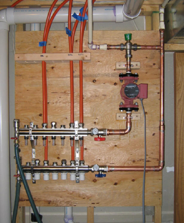
Radiant heating manifold. The
floor loops start at the upper (supply) manifold, and come back to the lower
(return) manifold. The manifolds were bought as a package that included
the manifolds, flow gages and shutoff valves for each loop, air eliminators
(on the left end of each manifold), temperature gages for each manifold, purge and
drain fittings, and shutoff valves for each manifold.
This manifold package was a bit pricy ($270),
but I have to say having the flow indicators, temperature gages, and shutoff
valves is a big convenience in determining what is going on, and in making
adjustments.
The supply pipe from the thermal
storage tank is the left of the two white 3/4 inch CPVC pipes coming down from
the ceiling.
The return to the storage tank is the
3/4 CPVC pipe to the right.
The return pipe connects directly to
the return manifold.
The supply pipe goes through the
thermal mixing valve (green top), through the Grundfos circulation pump, and
then to the supply manifold.
The thermal mixing valve mixes cool
water from the return line with the hot water from the storage tank to get the
temperature down to what you want to circulate through the floors.
The garden hoses connected to the
left side of the two manifolds were used to purge the system of air, and to fill
all the system lines with water, so that the circulation pump would work.
I was expecting this step to be difficult, given the very long underground line
between the storage tank and house, but it worked the first time.
This is really all there is to the
plumbing -- pretty simple.
Three more floor loops are to be
added soon to serve other parts of the main floor of the house.
Note: The
circulation pump was one that came with the house to circulate water in a loop
to reduce the wait for hot water in the bathrooms. When we bought the
house, it was running 24/7. At 85 watts to run the pump, this works out
to 750 KWH a year!, and $75 a year and 3/4 's of a TON of greenhouse gas.
I removed it from that job, and put it to work on the radiant floor -- I will
eventually replace it with a bronze pump with slightly larger capacity.
Gary 1/15/07