
Search
The Renewable Energy site for Do-It-Yourselfers
Tank Construction
and Placement
|
The construction I used for my 500
gallon thermal storage tank is detailed below. The tank is 88 inches wide by 40 inches deep by 36
inches high. I choose these dimensions to fit my space, and to allow the
tank bottom to use one full sheet of 4X8 plywood. The tank would
hold 550 gallons if filled to the brim. The capacity could be increased to
a little over 700 gallons by making the tank the height of a full sheet of
plywood (48 inches).
I was not able to find much in the
way of how to build a plywood tank out there, so this is my cut at it.
I've described it in quite a bit of detail -- if you see places where
improvements could be made, please send them in.
The structural logic for this tank
design is described here.
Some comments from Tom the tank
builder and others here.
|
|
2007-2008 Winter changes to the tank here ....
I'm not a tank designer by any
stretch of the imagination, so I don't guarantee that this is the best approach,
or even that it will
hold together. If you have suggestions for improvements, please send
them to Gary.
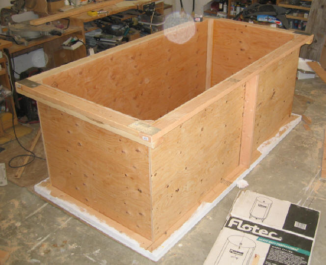
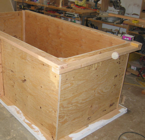
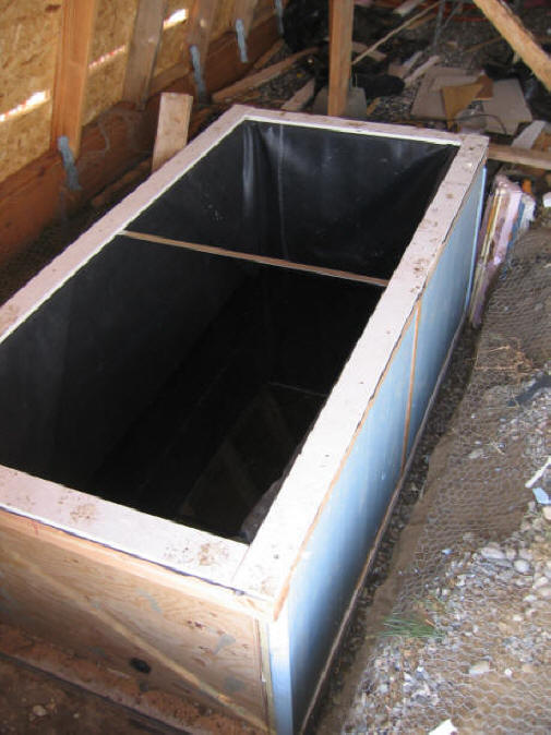
This is what the finished tank frame
looks like without the EPDM liner, top tension tie, or insulation.
The Base
The base of the tank is built on a
full sheet of 4X8 by 3/4 inch exterior plywood. The full perimeter of the
base is framed by 2X4's. The 2X4's support the lower edges of the tank
sides.
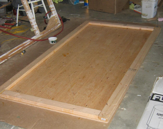
The picture shows the base plywood
sheet with the 2X4's around the edge. The 2X4's are nailed and GLUED to
the base. These 2X4's are under a lot of outward pressure from the sides
and ends, so make sure they are well secured to the base plywood.
The Sides & Ends
The sides and ends are also 3/4 inch
exterior plywood. This may be a bit thicker than needed, but the extra
cost of using 3/4 instead of 1/2 is minimal. The vertical edge of
each side/end is attached to the adjacent side/end by a roughly 2X3 piece
of lumber. The sides and ends are screwed and glued to this 2X3. The
2X3 is ripped to a nearly triangular shape so that the EPDM lining does not have
to bear against a square corner.
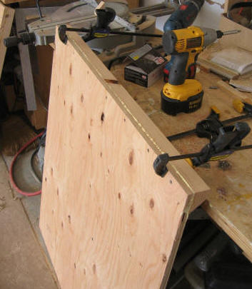
End Panel:
Shows the vertical edge member being
glued
and screwed to an end panel. The edge being
clamped is the vertical
edge of the end panel.
The edge closest to the camera is the bottom edge,
which will bear against one of the 2X4's
on the tank base.
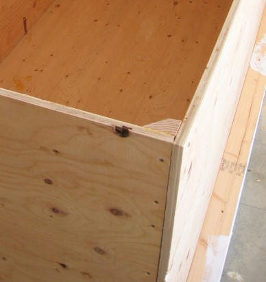
his shows the how the side and end
panels are joined by the vertical 2X3. The 2X3 is under a good deal of
load from the water pressure forces on the side and end panels, so screw and
glue it carefully.
An alternative to this side to end
joint technique would be to let the sides run past the ends, and put and run a
2X4 down the vertical ends of the sides. The end pieces would then be
glued and screwed to the vertical 2X4. This might well be a better way to
go.
Upper Edge Frame
A frame of 2X4's surrounds the upper
edge of the tank. The 2X4's lap over each other at each corner, and the
laps are glued and screwed to make strong lap joints.
Upper Frame:
The 2X4's are glued and screwed to
the sides and ends. Where the 2X4's overlap each other at the corners,
they are screwed and glued to each other -- it is important that these corner
joints are strong.
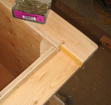
Close-up of the corner joint area.
As an extra measure, a 2nd 2X4 is run
across the each end and joined to the side frame 2X4's with metal splice plates.
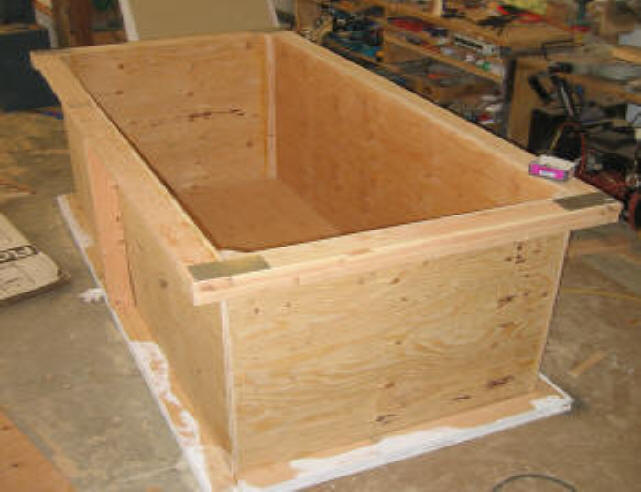
Shows the added end frame 2X4's with
metal splice plates. This also makes for a flat surface for the cover to
sit on.
Side Verticals
A vertical 2X4 is added in the center
of each side to break the sides up in to two panels.
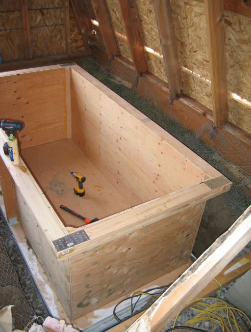
Picture showing tank in place.
The north vertical is visible to the left. It is tied to the lower frame
and upper frame with metal angle clips, and is screwed and glued to the side
walls. The picture also shows the metal tie
straps on the top frame installed.
Tension Tie
The tension tie is a galvanized metal
bar that ties the mid points of the two long sides together at the top frame.
It is important in that it cuts the bending load in the two top frame 2X4s by a
factor of three. Don't leave the tension tie out.
The tension tie is visible in this picture going across the top frame at the mid
point of the long sides. It is fastened to the top frame by two lag screws
(1/4 inch) that are hidden by the top cap pieces in this picture.
Installing the EPDM Liner
Carefully measure the size of the
piece of liner you will need.
Liner long dimension = (length
of side) + (tank height)*2 + (3.5)*2
Liner short dimension = (length of
end) + (tank height)*2 + (3.5)*2
The 3.5 inches allows the liner to
extend over the width of the top frame.
So, for this 88X40X36 inch tall tank:
Long dimension = 88 + 36*2 + 3.5*2 =
167 inches = 14 ft
Short dimension = 40 + 36*2 + 3.5*2 =
119 inches = 10 ft
Cut out the liner to size.
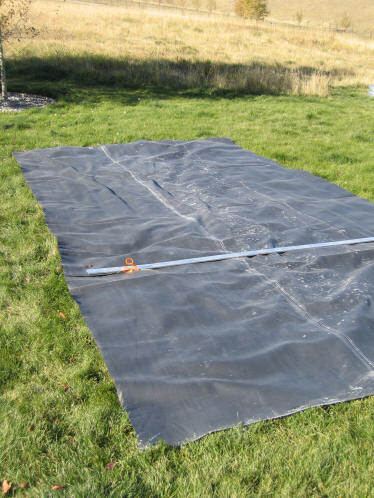
Trimming the liner to size from the piece cut off of the 20 ft wide roll.
At this point, mark each edge of the
liner at its mid point with a felt tip pen -- this will allow
you to line it up more easily when you put it in the tank.
Also mark the mid points of the tank
upper frame 2X4's.
Lay the liner over the tank, and work
it down into the tank opening. When it hits the bottom of the tank, take
your shoes off, and work from inside the tank.
Shift the liner around until the mid
points you marked on the liner line up with the mid points you marked on the top
frame 2X4's. Clamp the liner to the frame at these
mid point locations (as in picture below).
Work the EPDM around until you have
all the excess material in one large fold at each corner.
Make sure the EPDM has enough slack
in it so that when the water fills the tank it won't be stretched.
Tack the EPDM to the top frame with a
stapler (or the like) at a few places.
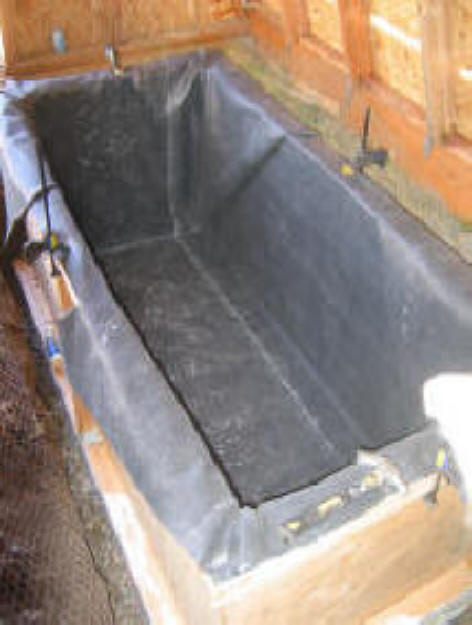
EPDM liner in tank, with the mid
points clamped down, and the excess material worked into folds at each corner.
Install the tension tie at this point
(see Tension Tie section above). Don't leave the tension tie out.
Now install the the four boards along
the edges to hold down the edges of the EPDM liner.
These edge boards hold the EPDM edges down, and provide a place for for the
cover to bear against. I used some of the left over plywood for these edge
boards, but there are probably better choices that would hold up longer.
Insulation
My tank sits on two thicknesses of
rigid insulation board. The top on is 2 inch thick polyisocyanurate, and
the bottom one is 2 inch thick extruded polystyrene (blue) board. I
made the top layer of polyiso insulation just in case the tank temperature gets
high enough to degrade polystyrene.
For the sides, I cut insulation panels from rigid
foam board insulation and "glued" it to the tank with the polyurethane in a can
foam material (e.g. Great Stuff). I added one more layer of 2inch foam
after the picture above was taken to bring the total R value up to about R26 --
this is probably more than is needed for an indoor tank, but mine lives outside.
Again, I used the higher temperature
Polyisocyanurate insulation for the the first layer, and the extruded
Polystyrene (blue) insulation for the outer two layers.
The Polyisocyanurate insulation is
sold by most lumber yards -- its the rigid foam board insulation that is usually
light brown in color, and typically has aluminum foil on the faces. It is
only slightly more expensive than the more common polystyrene.
Cover
The cover is made with a 2 inch thick
4X8 sheet of extruded Polystyrene foam board with a tempered hardboard
sheet glued to the top, and EPDM glued to the bottom. I plan to cover the
whole tank with some left over fiberglass batting from a past insulation
project. This should bring the R value of the top cover to about
R30.
Update: I find that it is important
to have the cover well sealed to the top of the tank. Without the
tight seal, the fiberglass bating that I had over the tank got damp from the
escaping vapor -- surprisingly damp in places.
I took the cover off, sealed all the
joints in the edge boards that hold down the EPDM liner, and then lag screwed
the insulating cover down to the perimeter frame 2X4's. This appears to be
working OK, but I think that the whole cover design could use some thought --
any ideas?
1/15/07 Update:
Most of the plumbing connections are
made to the west end of the tank. These connections are made above the
EPDM lining to avoid having to penetrate the lining with pipes. The pipes
actually enter the tank through notches cut in the lid just above the EPDM
liner. Once inside the tank, the pipes are routed down to the appropriate
level in the tank (high for the supply, and low for the return). In order
to be able to seal these connections up well, it is helpful to have the the west
end of the tank lid (where the connections come in) sealed down permanently.
But, the rest of the tank lid still needs to be opened to provide access to the
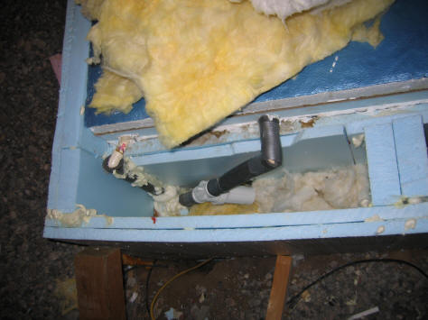
tank. I solved this problem by cutting the notch shown in the
picture below. The notch allows the west end of the tank lid to be
permanently sealed down, and the east part of the lid can still be hinged up for
access using the notch as the hinge line. The cut does not penetrate the
EPDM, so no fancy sealing is needed between the fixed part of the lid and the
part that can be opened. To restore insulation, the notch cutout is just
placed back in the notch.
This seems to be working well.
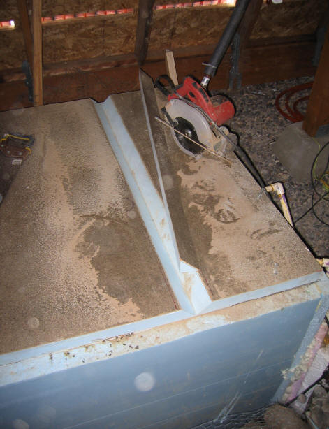
Notch to make the left part of the
tank lid openable. The part of the lid to the right of the notch is
permanently sealed down to make it easier to do a good job of sealing the
plumbing penetrations.
The return line from the collectors
comes into the top of the tank just behind the saw.
The two CPVC lines going off to the
house can be seen just just to the right of the tank.
The supply line to the collectors and
the Taco circulation pump are on the opposite end of the tank in an insulated
box. The collector supply line enters the tank about 6 inches from the
bottom, and is the only line that actually penetrates the EPDM liner. The
supply line immediately makes a 90 degree turn upward, and connects to the
circulation pump. The circulation pump is mounted such that it is below
the tank waterline, and therefore retains its prime when the pump shuts down.
The supply and return line from the
house entering the tank.
These are 3/4 inch CPVC pipe. There is a polypropylene and stainless steel
strainer in the supply line (which is probably unnecessary). I
built a box around the pipes using the foam board insulation, and then filled
the box up with fiberglass batting (after this picture was taken). This
arrangement has handled several -20F nights now with no problems.
The pump
Placement
The tank should be placed on a flat
and level surface that will take the 4200 lb water weight. A concrete pad,
gravel pad, or well compacted soil. I think that it is best to keep the
tank on the surface, and to provide drainage to make sure that the wood stays
dry. I violated this rule with my tank, in that it is sunk in the ground
about 2 ft. In my case, the soil is dry, the tank is inside a shed that
protects it from weather, and the tank bottom sits on 3 inches of open gravel
plus 4 inches of insulation -- I'm still not sure this is a good idea, and I
would avoid it if you can.
Suggestions
for Improving the Tank Design:
While the tank design above is
working out fine in use, there are always things that can be improved -- here
are some suggestions from visitors, and some after thoughts from me:
From Tom, who used to be in the
business of building solar heating storage tanks:
-
Tom thinks the basic design is
good.
-
Using treated wood for the framing
is probably a good idea, since the framing may well live in high water vapor
conditions.
-
Don't use polystyrene insulation,
as it will not hold up to tank temperatures. This makes me feel better
about making the first layer of insulation on my tank from polyisocyanurate
insulation -- I thought I was being a bit paranoid, but I guess not.
-
Placing the insulation on the
inside of the plywood gives the EPDM a smoother surface to bear against.
I suppose that one might put one inch of polyisocyanurate insulation on the
inside of the plywood, and then use polystyrene or even bats or fill
insulation outside the plywood.
Other suggestions:
-
Take pains to seal the cover to the
tank body. This keeps a dry atmosphere outside the tank, which is better
for the wood and the insulation. It also eliminates a source of heat
loss. Ned suggested using tie down straps to do this. Lag
bolts through to the upper perimeter frame might also work well.
Here is one scheme to consider if you
need a well insulated tank:
It takes into account the fact that
if you want a well insulated tank, that the insulation quickly becomes the most
expensive element of the tank.
Build the tank above ground level.
This makes it easier to incorporate cheaper fill type insulation (see below).
I actually think that the above ground is better all around. It should be
easier to build, easier to make connections, easier to inspect, easier to fix
problems, and less likely to be subjected to moisture damage from the ground.
Build the basic tank frame as shown
above.
Place 1 inch of polyisocyanurate
inside the plywood tank walls. This makes a smoother surface for the EPDM
to bear against, and the polyiso insulation has a high enough temperature
capability to take the tank temperatures. Putting only one inch of the
insulation inside the tank keeps the reduction in tank volume to a minimum.
2/20/07 Update: unless you
really need the tank volume, I would seriously consider putting 2 inches of
the polyiso insulation on the inside of the plywood tank walls and floor.
This has the advantages stated above, and it provides a very good start on
insulating the tank because insulation inside the tank has no thermal
bridging. When you insulate outside the tank, you have to insulate
between the framing members, and these act as thermal bridges and reduce the
overall R value.
Next summer, I plan to drain the
tank, remove the liner, and add 2 inches of polyiso inside the tank -- I think
that with this added insulation the tank temperature drop on a very cold night
will get down to about 0.5F.
Place as much rigid foam board
insulation under the tank base as you need to meet your heat loss requirements.
Make sure that the tank is uniformly supported over the full base area.
Build a lightweight enclosure around
the sides of the tank, and fill the area between the tank frame and the
enclosure with bat or loose fill insulation. Make the space between the
tank frame and the outer enclosure large enough to accommodate as much R value
as you need to meet your heat loss requirements. It will be cheaper
to achieve high R values this way than stacking multiple layers of rigid foam
board outside the tank.
Make the top with a sheet of EPDM
glued to one or more thicknesses of rigid foam board insulation. Again the
first layer should be polyisocyanurate insulation. Make the
cover more rigid by gluing a sheet of plywood or hardboard to the top of the top
layer.
Work out a way to seal the top down
to the tank frame that prevents water vapor from getting out. This keeps
your insulation from getting wet, and eliminates a source of heat loss.
Cover the whole works with fiberglass
insulation bats.
I don't think that you want to put
plastic over poly film over the insulation, as this will prevent any water vapor
that does get out of the tank from dissipating into the air.
Check the state of the tank structure
and check that the insulation is not getting water logged from time to time.
Gary 10/25/06 Revised 10/30/06,
11/2/06