Search
The Renewable Energy site for Do-It-Yourselfers
Tom's Large Solar Heating System
This page describes Tom's very well done solar heating system.
This is a great project with details on design and construction of a
large solar collector array, a large thermal storage tank that doubles
as a work bench, integrating solar and wood boiler heat sources in the
same system, a very nice heat exchanger fabricated from rigid copper
pipe, and details on integrating radiant heating with solar.
Thanks very much to Tom for providing this information!
Tom's other projects on Build It Solarl...
|
|
Building my 336 Sq ‘ Home
Solar Collector
Building the Collectors
I wanted a solar collector array to
heat my 2,000 Sq’ garage, possibly preheat my domestic water, and to heat
the finished basement of my home. I thought that if the system worked well,
I could add in-floor heat to several rooms on the first floor of my home as
well. I wanted the system tied to my existing wood boiler so during extended
periods of no solar exposure; I could supplement heat to the storage tank
with the stove. To maximize the different materials, and get a good
collector size, I elected to go with 10’ x ½” copper tubing risers,
connected to ¾” copper manifolds. For ease of handling, and to facilitate
construction inside my garage, I built 8 separate 4’ x 10 ½’ panels. Each
panel was built with the top and bottom permanently attached, and one side
being used as a common member to two panels.
I had recently dismantled a “test panel” made with 5/8” PEX and wanted to
re-use the aluminum absorbers on my permanent collectors. Since I was using
½” copper, the absorbers pressed for 5/8” PEX were too large to work without
some modification. As an experiment, I placed the absorber over a short
piece of ½” copper and installed my “Vice Grip” tools on it, tightening them
up as much as possible. I also briskly tapped on the outside of the clamps
to “set” the aluminum to the tighter gap. As a result of this process, I
ended up with 90% contact area between the aluminum and copper, where I was
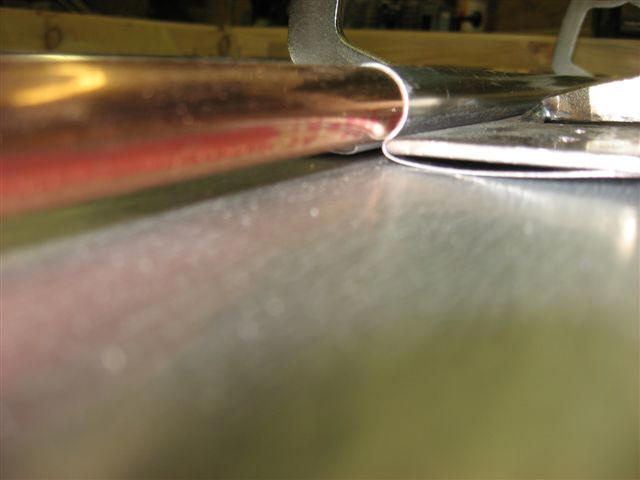
getting about 70% with my standard stamping process. (See photo). Every
aluminum absorber for this collector was processed in the same manner;
pressed out for 5/8” ID and re-formed with my clamps for ½” ID.
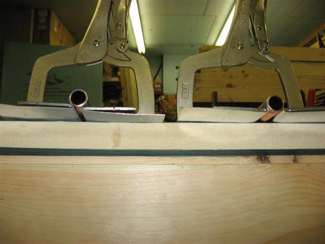
Left tube shows the nice full wrap achieved by using the fins formed for 5/8
tubing on 1/2 inch tubing.
Note that you may be able to
talk Tom into making tubes for your system...
Click on pictures for full size
|
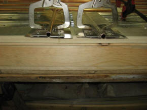
Better view of Tom's fin clamp made from
vice-grips |

Close view of the 90% fin wrap
on the tubing. |
With copper the material of choice for my tubing, I looked for the most cost
effective method to attach my ½” risers to the ¾” manifolds. Reducing “T”s
were quite expensive. I had spotted on Gary’s site a builder in Europe that
“brazed” his connections, which looked like a much cheaper option. I set up
a template on a piece of 3/8” board that I could lay beside the copper and
mark out my riser spacing. Once the spacing was established and marked, I
center punched the locations and drilled them out with a ¼” bit. This hole
was easy to drill, and allowed further accuracy for the 5/8” drill. I did
use a drill press, which helped some, but this process could easily be done
free hand as well. For the final fit of the copper, I used a “ream bit”.
Although these bits were too long, I had an old bit from my shop that I was
able cut off (with a cut-off wheel). The ream provided a beautiful fit
between the manifold and the riser.
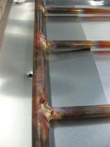
Half inch riser tubes brazed to 3/4 inch manifold.
To get the proper penetration of the ½” copper to the manifold (I didn’t
want to inhibit water flow by too deep of penetration into the manifold), I
installed a piece of ½” copper in the ¾” manifold before fitting the risers.
This prevented excessive penetration, and provided a consistent depth for
every riser. I learned the hard way not to leave this in past “tacking up”
the copper. If left until everything was brazed (or soldered), the copper
was impossible to remove without damaging the entire manifold. I elected to
braze my connections, mostly because of fear of leaks and seeing the builder
from Europe doing the same. In retrospect, I would solder in the future. I
soldered one collector preciously with the same type of fit (drilled instead
of factory “T”s), and it worked fine. The brazing was challenging (and I’ve
done a lot of it in the past), and another issue cropped up later. When
first erecting the array, I had a little condensation get to the open
collectors. EVERY braze joint corroded! I don’t know if the brazing flux was
the culprit, or a reaction between the aluminum prep and the brazing
material and/or the flux. Bottom line, I ended up sandblasting every brazed
joint on my completed panels and repainting them. Not a single soldered
joint (I did have several in each panel where the panels were mated) had an
issue. Just to show you can’t let your guard down, I tested every copper
grid for leaks after brazing except for the last one (number 8). I did not
have a single leak in the first 7. I didn’t check the eighth panel, and when
filling the system for the first time, I had a leak in that panel. Luckily
it was on the bottom and easy to get too. I soldered that joint over the
brazed joint and it sealed up fine.
Having experimented with 12 or more panels before starting my own system; I
had developed a design that worked the best for my application. Knowing the
backside of my collectors would be exposed to the elements (weather and
creatures), I needed the back of them to be a solid board. I used 2x6’s for
the side and bottom frames, insetting the ¾” OSB by 1” so the edges would
not be exposed to the weather. I placed 1” Styro (the high temp variety)
inside the collector on top of the OSB. I like the Styro as the last
material before the absorber and tubing, as it insulates the heat collection
area from the rest of the collector. With ¾” of board, and 1” of Styro, 1
5/8” drywall screws were the perfect length for attaching my absorber
tightly to the panel. I used my “Vice Grip” tools to squeeze the absorber
tightly to the copper before installing the screws. I found, when properly
tightened, the screws were very effective in holding the aluminum tightly to
the copper risers. My pre-pressed absorbers help with the fit as well,
requiring significant force to “snap” them on the copper.
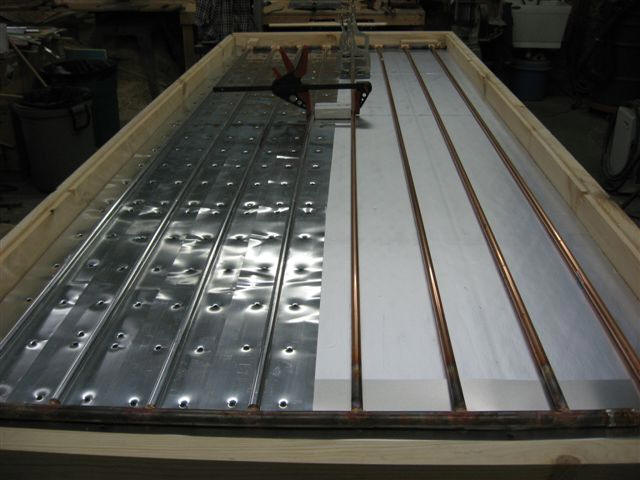
Fins being secured
through the insulation board to the underlying OSB.
Click on pictures for full size
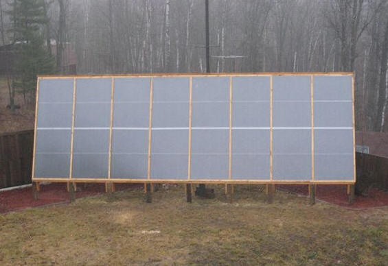
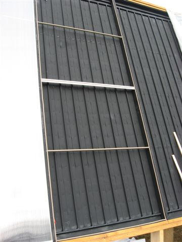
Mounting the Collectors
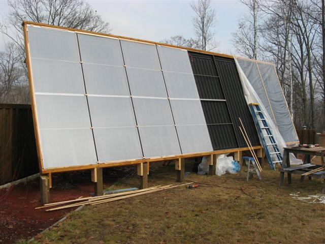
Partially glazed collectors with the twinwall polycarbonate glazing installed on
the left 4 bays.
The best location for my solar collector array was on
top of my underground garage. This presented some unique challenges, since
setting 6”x6” poles in the ground deep enough for the wind loads was not
possible. I had a pile of “take-off” bumpers from trucks we sell for
governmental plow trucks. The trucks are delivered to us with a cheap
“transport bumper”, and are removed to install the plow hitch and plow. These
were 8’ long and about 14” wide, had a small lip at the edges, and worked nicely
for welding attachment members to for later attachment of the 6x6’s and the rear
support brackets. I dug down 12” to my roof, creating a 16” by 10’ trench to
place the modified bumpers in. I placed 4 of the 8’ long units in, and used
shorter versions of the same design at the 5 other 6x6 support locations.
The solar collectors were set in place, with the
help of a couple able bodies. 10 ½’ x 4’ panels become a lot larger when placed
2’ above the ground and being steadied in the wind while setting up temporary
supports. Final supports were not installed until everything was set level and
to the proper tilt. After consulting with Gary, I decided on a 10-degree tilt.
Just enough for better solar exposure and slightly less wind exposure, yet not
enough to hold a lot of snow or moisture. Once the array was erected, I became
concerned that I had enough rear supports. I fabricated some more of my “unique
supports” for the garage roof, and installed 3 more supports running
significantly farther back than the original 4 supports.
|
 |
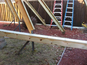
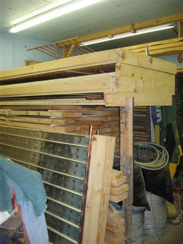
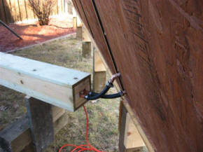
Pictures showing the support system. |
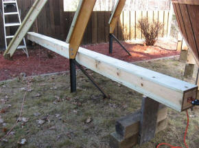
Support struts and the insulated
pipe line to the storage tank. |
I had built the panels with provisions to solder
unions at the top and bottom where the panels meet. The manifolds were set with
a ½” rise per 4’, starting at the middle panel and working upward to the left
and right. The top manifolds duplicated the rise and at the far left and right
ends, I placed double 90’s and the returns run down hill, parallel to the
manifolds, “T”ing at the center of the array and dropping down next to the
inlet. The inlet and outlet for the system exit the array within a few inches
of each other at the right side of panel #4, essentially the lowest point for
the array.
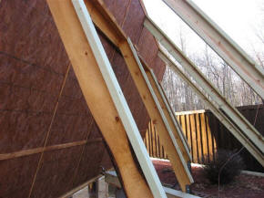
When building the panels, I planned for 3 supports for
the glazing. With 10 ½’ of glazing, I wanted enough support for the glass or
polycarbonate to withstand wind loads. The center support is 1 ½” x 1 ½ x 1/8”
aluminum angle. The secondary supports between the angle, and the top and
bottom, are Gary’s customary ½” conduit. I cut a “rabbit” for the glazing so
the finished height of the glazing would be just above the edge boards of the
collector. I wanted to install a “trim board” over the glazing edges, to both
protect the edges from weather and to dress up the appearance of the array.
Picture showing glazing supports.
My original plan was to use glass for my glazing. I
had built a previous panel with glass and it looked so professional. But the
price was pretty prohibitive, about $2.60 per square foot. I have had zero luck
finding “true” polycarbonate in my local area, short of ordering it for $1.50 to
$2.50 per sq’ (single wall), with the cheaper material being corrugated and
requiring more expensive sealing material. About a week before I was going to
place my order for glass glazing, Axel Peikert from Oshkosh came up to my
location to purchase some absorbers. He mentioned an option to “Pool” our
purchasing and place a direct order with one of the polycarbonate manufacturers
not far from him. He was willing to drive down to Janesville, WI and pick it
up, putting my final cost at $1.50 per sq’ for twin wall polycarbonate. That
ended up being my solution to glazing, and it’s a dream to work with. It cuts
easy, and is light weight, making handling it a breeze. During the 2 weeks
waiting on the glazing, I covered the array with 6 mil plastic.
I worked out a “wholesale” pricing arrangement with my
local True Value dealer on hardware and weather-stripping. I installed a 3/8”
wide by 3/16” thick weather-strip along the entire “rabit” and across the 3
horizontal supports. Caulking was used at any spot there could be water
penetration.
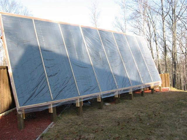
Collector covered with plastic film waiting for final twinwall glazing.
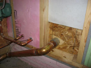
Plumbing the array to my tank had to be done above
ground, as my unique roof area was not conducive to an underground chase. I
devised a plan to use 1” treated lumber and Styrofoam, creating a box with a
minimum of 2” of Styro on all sides of the copper tubing. I also ensured the
copper tubing was separated by 1” to avoid heat loss on my return line. The
biggest challenge with the “chase” was to get a good fit at the collector. I
had numerous angles to deal with, needed to get it insulated sufficiently and
protected from the weather.
Click on pictures for full size
|
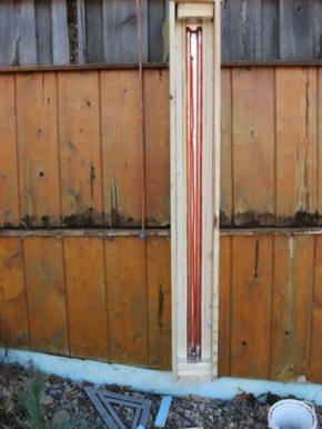 |
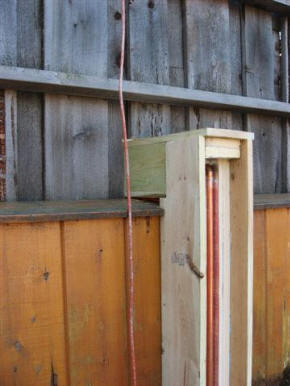
Pictures showing the insulated pipe
line from collectors to storage. |
 |
Storage Tank, Controls & Heat Usage
I built a storage tank using Gary’s design of wood and pool tank liner. The
area I planned to place the tank was in my workshop of my heated underground
garage, and I wanted the tank to serve as a work bench as well. The initial plan
for my tank would have worked well for a work bench, but after incorporating my
wood boiler into the system, the tank ended up a little taller than a normal
workbench (for gravity water level balance, to be explained later). The tank is
made with 2x4’s and ¾” OSB, and is 3’ wide and 12’ long. I have at least 4” of
Styrofoam insulation on all sides of the tank. Two aluminum straps have been
placed at 4’ intervals across the long distance of the tank for side pressure of
the water over this distance. These served well to hang the heat exchanger for
my Domestic Hot Water (DMH), which I wanted close to the top of the tank for the
highest water temperature.
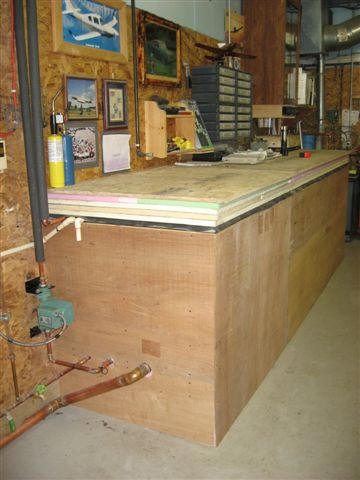
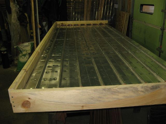
Left side End view of finished tank, with Luan on sides to protect insulation.
Tank being used as work bench.
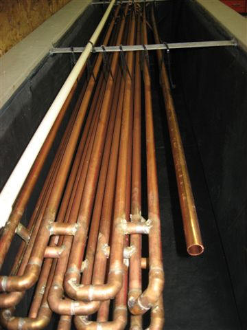
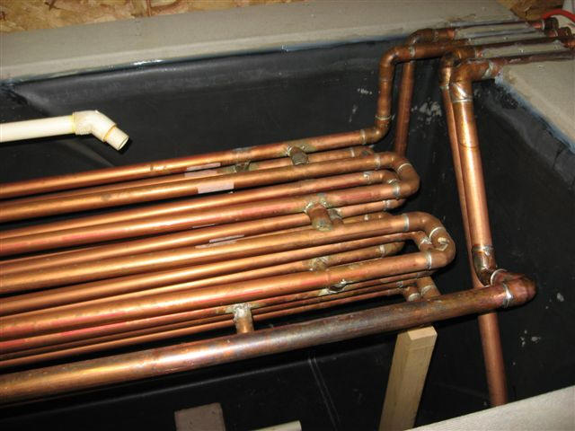
I built my DHW heat exchanger out of ¾” rigid copper, finding the cost of
this much better than “Soft Copper”, and wanting a heat exchanger that would be
very efficient for large water usage. The heat exchanger consists of 200’ of ¾”
copper, 4 levels of 5 tubes, each level tied together in one long serpentine
loop. I added small pieces of scrap copper to the sides of the unsupported runs
to create a fairly rigid “grid”. Just to be clear, these pieces do NOT have
water running through them, they only serve as supports. The 200’ of copper
create an eight gallon reservoir on the supply side of my water heater. I’ve
found, since going live with the system, that even once depleting the first 8
gallons of water to my water heater, the water exits my heat exchanger within 10
degrees of the current tank water temp. Four showers in my household within an
hour the day after Christmas and my water heater never turned on. Yes, I was
grinning.
Click on pictures for full size
|
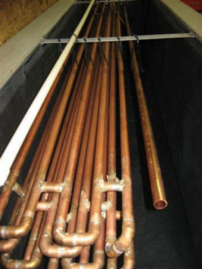
End view from left side of tank, showing DHW Exchanger
suspended from aluminum strips, CPVC "hot water" line
from wood stove running to other end, and "pick-up"
copper line for suction side of Hydronic Loop. |
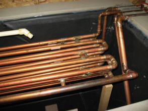
Right side of tank, showing DHW Exchanger connections
going out of the tank, the 1" hydronic copper
lines (in and out) and the CPVC
outlet from the wood stove. |
My plan was to also incorporate a series of valves and dual supplies to
utilize the solar tank and heat exchanger for the 2-4 times a year I drain,
clean and refill my 350 gallon hot tub. I cannot use treated (or softened) water
in the hot tub, but wanted to utilize the heat from the solar tank for my tub
fillings. The valves allow me to bypass the exchanger for my DHW temporarily,
run untreated water through the heat exchanger, and hook a water hose for
filling the tub into that loop (close to the tub no less). The hot tub usually
runs for 8 hours to bring the water temp up after a filling, and I envision
reducing that “heat time” to under an hour with this feature. By running the
water through the heat exchanger, and moderating the flow to meet desired output
temp, this feature should bring back substantial savings, plus the satisfaction
of knowing I preheated the hot tub water with solar (or wood) energy.
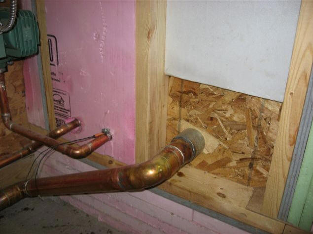
I decided to be brave on the water supply pipes for my solar collector and
“balance tube” for my wood stove. I had concerns about running my supply to the
circulation pump for my solar collector over the side of the tank. I’ve got
extensive experience with hydronic heating, and have worked with a lot of
problems relating to air locked pumps. Although not likely to be a problem, I
did the unthinkable, penetrated the sidewall of the tank. I had a nice piece of
aluminum that served as a “through flange” for the inside of the tank, since I
have 1” of Polyiso on the inside of the tank. I calculated the distance needed
from the outside wall of the tank (the OSB) to the inside surface of the
aluminum. I then found the appropriate length nipple to thread into the unions,
using the unions (with washers on the ¾” lines) to develop a very tight fit of
the “pass through” piping once the pipe arrangement was tightened. I added
silicone to the back side of the aluminum plate, and around the unions on the
inside of the tank. On first filling, I had a leak! I was devastated. I drained
it down and upon a recollection of my razor knife dropping into the tank at one
point during the project, decided to closely inspect that area. As tough as the
rubber was to cut, the knife had penetrated the liner. Having a background in
tire repair, I used a tire patch with appropriate glue and the leak was easily
fixed. I never had a leak at any of the “tank penetrations”.
Click on pictures for full size
|
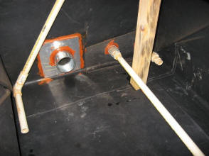
Inside view of tank penetrations, with
aluminum plates and sealant. |
Outside view of tank penetrations. |
| |
Note -- As another possibility, there are
some pretty good commercial "bulkhead" fittings for penetrating tank
walls. I used one from our local AG store on the
Solar Shed tank. Its made from
polypropylene and has held up well so far (5 years) -- Gary |
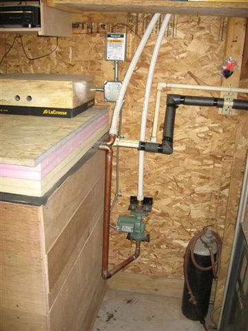
Solar heating during the winter in the U.P. of Michigan is a challenging
venture. We get marginal sunshine, especially during November, December, and
early January, which are the shortest solar days anyway. I decided to connect my
wood boiler for my 2,000 Sq’ garage to the solar tank. The boiler will
supplement heat to the tank during extended periods of insufficient solar
energy. The simplest system was a circulation pump taking hot water off the top
of the wood boiler, and the water essentially flowing back to the bottom of the
boiler with a “balance tube”. I installed a 140 degree temp switch on the side
of the wood boiler which turns the pump on once the boiler has reached that
temp. I tried one ¾” return line, then two, then two with extra entries into the
boiler. The water would simply not return by gravity fast enough, creating a low
water level in my wood boiler. Even a restrictor in the suction line to the pump
could not slow the imbalance enough unless restricted so slow it was useless. I
finally got serious and ran a 2” copper balance tube, with a ball valve, and
that worked great. As you can see, I make up for my engineering deficiencies
with incredible tenacity; keep trying until it works. :>)
| Click on pictures for full size
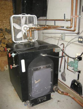
Wood stove (boiler). |
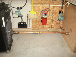
2" copper "balance tube" from tank to wood stove. |
For controls between the collector and the tank, I used a 120 degree snap
switch, which ensures I have at least that temp in the collector, and then the
GL-30 Differential Controller that Gary recommends. The differential controller
makes sure the pump only runs when the water returning from the collector is
warmer than the water coming out the bottom of the tank. A note here, when
wiring up every “circ” pump in my system, I wired in over-ride switches to turn
on each pump for testing purposes. Once the tank was closed up, I would have no
way of checking water temp (up until now my “I.R.” gun was great for that) and
water level. Since the water in the solar tank was common to the wood boiler,
and keeping a very consistent level was critical, I installed a “sight tube”
with the high mark indicated on the tube. For water temperature I installed
digital temp meter with a submersible probe on a 10’ lead.
| |
Note -- The GL-30 is unfortunately not
made anymore. Some others to look at would be Steca, Caleffi, ...
Gary |
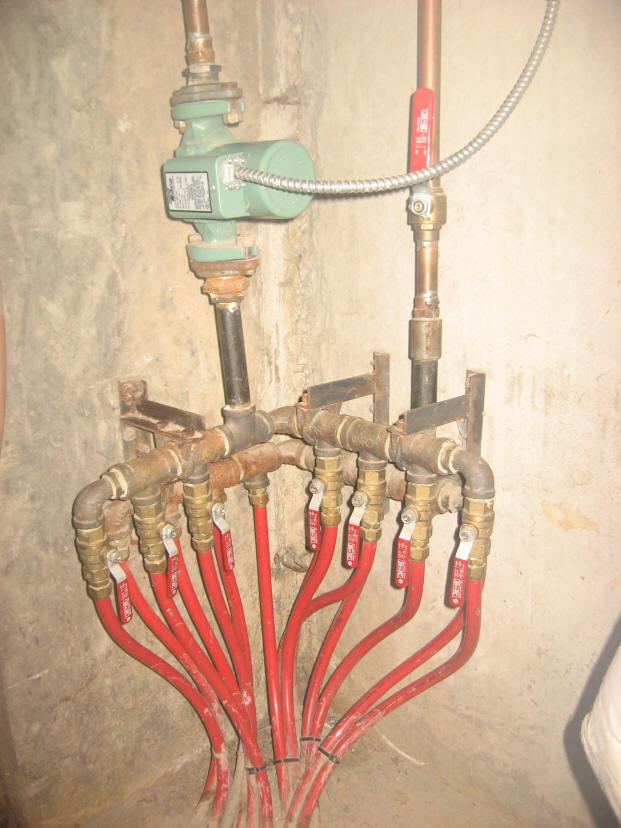
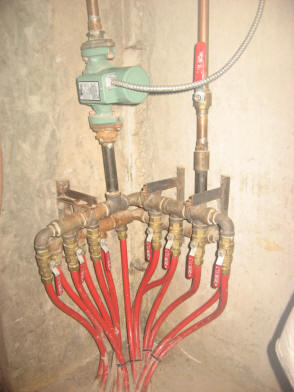
The last project before closing the tank and putting this project to bed was
running a hydronic loop to my basement (up 7’ from my garage level). I used 1”
PEX for the loop, running the PEX to home made manifolds in the basement. I
wanted to touch on this, as this is something I did 12 years ago when building
my underground garage and installing the in-floor heating system. Having worked
with 3 different hydronic systems at my truck dealership, and using the
“expensive hydronic manifolds”, I had developed an opinion about them. Rarely do
you adjust the valves once past the initial start-up. I assembled my own
“manifolds” using black pipe and ball valves, and the system in my garage has
worked flawlessly for 12 years, with considerable less cost than the commercial
manifolds. I assembled the same type of manifolds (supply and return) for this
system, allowing room for expansion for more zones at the manifolds by just
adding more pipe “T”s.
|
1997 In Floor Manifolds.
Shows earlier version of "Home Made Manifolds"
from 12 years ago |

2010 Hydronic Manifolds.
Set up for my basement hydronic.
Valves installed temporarily for purging
air and priming circ pump. |
|
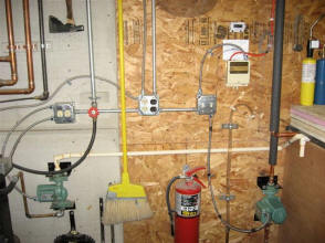
Switches and pumps for wood stove
and solar collector, GL-30 control,
temp gauge and sight gauge
for tank water level. |

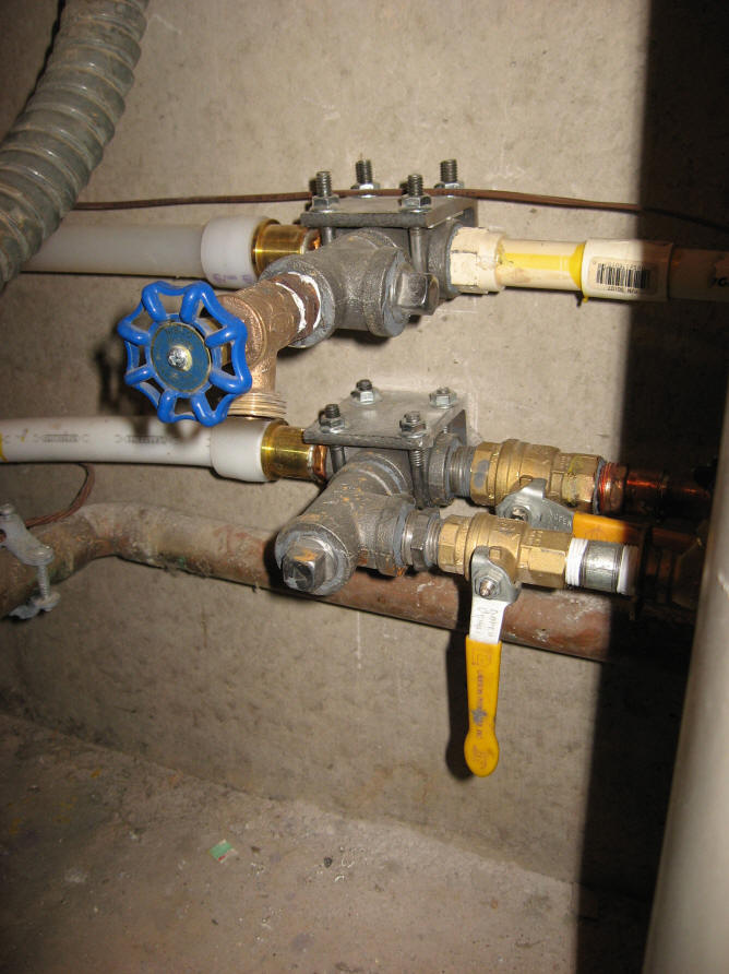
View of right
end, showing plumbing for
DHW and Hydronic pump, controls and plumbing.
|
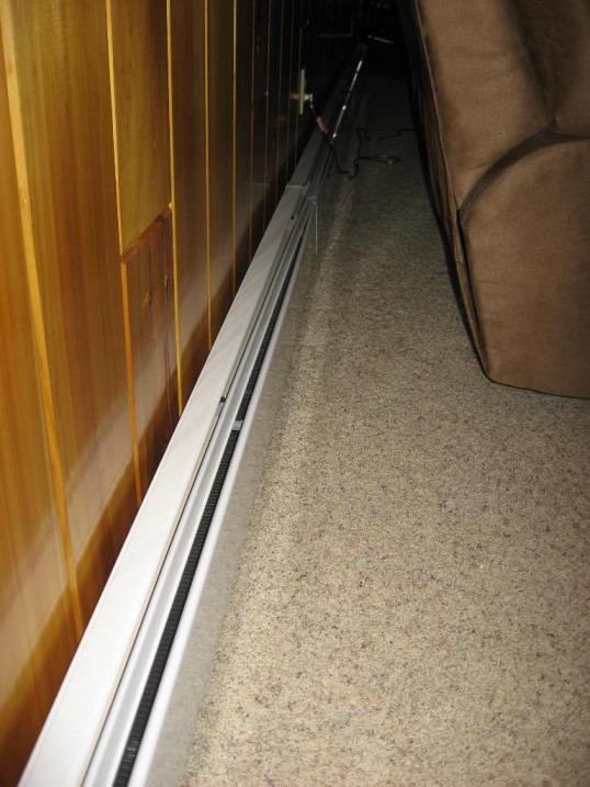
At this time I have 22’ of “Fin Tube Radiators” installed in the basement of
my home, heating the finished basement warmer than it’s ever been. A thermostat
is installed in the basement, controlling a relay which ultimately turns the
circulation pump on and off, based on demand. A note on this, I have yet to see
water temps over 135 degrees, and I’m getting sufficient heat from the fin tubes
until the water temp drops below 110 degrees. A local “plumbing and heating
expert” told me this wouldn’t work, but it does, obviously with lower efficiency
than the fin tubes would produce with 160 to 180 degree water.
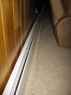
Basement fin tube radiators.
This same “expert” told me I couldn’t run a hydronic loop without it being a
“closed loop system”, which I am presently using on every other hydronic system
I have. Talking with Gary, we could see no reason this wouldn’t work, as we have
no problem filling our collectors with an open loop (none pressurized) system. I
did run over the top of the tank for the pump supply line, simply because the
tank was full of water and it was the quickest method. This system draws from
the top of my tank, using the actual tank water, and returns to the bottom. I
did this to create a “mixing” of the water in the tank, but it has served
another nice feature. The hydronic loop to my basement never “drains back”, so I
never hear air in the system upon start-up. A note on this; every individual
system (solar, wood, & hydronic) draws from one end of the tank, at the top or
bottom, and returns the water at the opposite end of the tank, at the opposite
level (top or bottom). When any system is running, I’ve found less than 3
degrees of difference in the water temp from the top to bottom. It’s clear this
design creates a good mixing of the water in the tank, eliminating
stratification normally found in a water tank of this size.
Results to date
Sadly, the sun has been a rare event in the U.P, since going live. During the
few days of decent sun, I’ve been running heat into the basement as the tank has
been warming up, so hard data on solar heat gain is not available. In addition,
during the shorter days of the year, with the sun significantly lower during the
day, I’m getting some shading from my house by 2 PM. This was unavoidable, and a
trade off I knew I was making with the system. By March, this issue will be of
little concern, with the sun higher in the sky. On the one day we had good sun,
before closing my tank and having anything drawing heat from it, I saw a gain of
8 degrees per hour. With a 420 gallon tank, and heat loss certainly an issue
with the tank uncovered, I calculate I was getting around 4,000 BTUs per panel,
or 32,000 BTUs an hour from the array. Until we get decent sun, at least excess
heat from the garage wood stove is being used for curbing my DHW expense and
putting heat in my basement.
Tom
Tom will answer email questions -- you can reach him at: toms1 AT chartermi
DOT net (replace At with @, DOT with .)
Tom's Other Projects
Tom has sent in several great projects --
see them all...
Gary December 8, 2009, Jan 24, 2010