Search
The Renewable Energy site for Do-It-Yourselfers
Tom's Wind Turbine
-- Electrical Hookup & First Power!
Pulling Wire Through the Tower
With the tower done and
functional, it was time to finish the generator assembly and wiring. The first
project was pulling wire up the pole. This would be done with the tower laying
down, but pulling 140' of wire through all the obstacles in the tower piping was
not going to be easy. My electrician (a friend helping for free) advised me code
did not allow the wire to hang more than 100' without support. We decided to cut
an access hole halfway up the tower for easier wire installation, and we could
install a wire support at this spot as well. I welded in a short piece of 3"
pipe at the center access and at the top of the pole. We would wrap the wire
around these supports and tie wrap them. I thought the numerous 1" x 2" pieces
of steel welded into the pipe for cable supports (we ran them completely through
for better strength) would be the difficult spots for the fish tape. It turned
out the pipe welds, where they were joined, were the real obstacles. It took
quite a few tries to get the fish tape through each section of pipe in the
tower. Pulling the wire was pretty easy once the fish tape was installed.
Tail Art
I had a vision of a tail "mural" I
wanted, but was reluctant to spend more money on this project. I found a picture
of a face protruding out the bottom of a cloud, blowing more cloud out to a
lower set of clouds, with a vortex. Knowing my art would be displayed 140' away,
I thought I would give it a try myself. The process was slow, but the results
were very satisfying. Once the mural was complete, the tail board was bolted to
the tail. A re-balance of the blades was also required after paint. I ended up
pretty close, needing only a couple of small pieces of strap, which I bolted on
with the blade plates.
Control Panel Wiring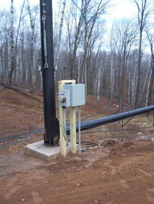
I installed two 4x4's right along
side of the concrete tower pad to place the control panel on. Prairie Turbines
provides the information on how to build and wire the complete enclosure, but
the "Micro Controller" (one component of the controller) can only be purchased
from them. I elected to buy the complete "Prewired Enclosure", concerned that
time was going to be an issue with winter coming. A ditch was trenched from the
tower to the garage where the wiring would be run to my garage "sub panel". WE
Energies, my local utility, had just inspected and approved a similar wind
generator about 70 mile away, so my "Grid Tie" application and approval process
was pretty easy. They require a "visible disconnect", which they prefer be
located by your service meter. They allowed mine to be located on the garage
near the generator, saving me considerable expense and work, but required
placards be placed at the service meter and the disconnect.
We installed a meter on the wiring coming out of the tower (before the
controller) to monitor generator output. Wiring the controller was pretty
straight forward. Wiring coming out of the tower consisted of; 3) 8 gauge wires
( we used 8/3 w/ground Romex), 1) 14/2 Romex and 1) 14/3 Romex. The three 8
gauge wires run from the generator as our main power wires. The 14/2 controls
brake function, and the 14/3 is for the "Hall Device", a magnetic impulse sensor
that signals motor RPM back to the controller. Wiring from the controller to my
disconnect, and then on to the sub panel, was 8/3 w/ground.
Generator Wiring and Checkout
We had to change the wiring on the
motor to get the proper voltage. This procedure is described in the manual. The
slip ring transfers the power from the tower to the generator without "winding
up" the wiring. Initially I designed the slip ring clearance to the generator
too close. Conversation with my friend Wally, who erected a Prairie Turbine 70
miles away, revealed that too tight of clearance will cause a "short" in the
generator. Reviewing my options, I determined the best course of action was to
remove the generator, shaft, clutch and bearings, and modify the mounting area
for the slip ring. I was able to drop it into the bearing assembly by about an
1", and I also had room to shim the generator, shaft and bearings by another
3/8". This provided ample room for the wiring and connections where they exit
the top of the slip ring. I also fabricated a "T Support" to support and secure
the wiring. It was essentially a 1" PVC "T" with 4" of PVC coming out each
direction. The top of the "T" was sawed of in the middle, creating a cradle to
lay the wiring in after making the connections. The bottom of the "T" was ground
down until it fit snugly into the slip ring center. I tie wrapped the wiring
tight to the "T" and this provided me with plenty of clearance between the slip
ring and the generator.
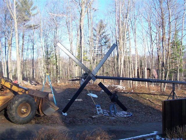
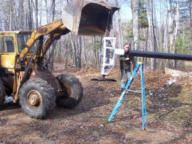
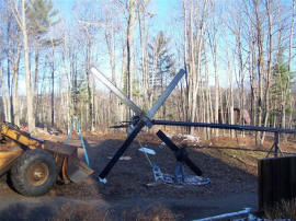
Installing Generator on Tower and
Tower Raising
We hung the generator assembly from my front-end loader at the appropriate
angle, and my son Cory fed the wiring through the yaw bearing and slip ring as I
installed the assembly to the tower. I powered up the generator and after a 30
second delay ( programmed by the controller) the motor brake released. I tested
the hall device, but could not get a signal. The hall device consists of an
aluminum wheel bolted to the back of the motor, and a small magnet, imbedded in
the aluminum, swings past the hall sensor. The first magnet I used didn't work.
I didn't find one with the hall device inside the controller, so I used one my
wife had laying around. I eventually found the magnet shipped by Prairie
Turbines, stuck to the inside of the enclosure, and installed it in the aluminum
wheel. A re-test and the system was now working. The final electrical test was
to verify the motor "direction" wiring to be correct. This required "spinning
up" the blade hub because we are trying to run a 3 phase motor on single phase
power. Power has to "jumped" to the "main relay once the motor speed is high
enough. Several attempts were futile until I installed a long bolt in one of the
blade mount holes and used this to get the speed of the motor high enough to run
it. We found the motor direction was correct.
On Wednesday, November 12th, we installed the blades and the tail. I had to make
an adjustment on the torque limiter, which protects the motor brake from
excessive force and wear if the turbine is shut down while the blades are
spinning. The cowlings were installed and we were ready to raise the generator.
My wife was the only helper at this time, and she was really nervous about the
lift. An interested neighbor had perfect timing, coming over to see the project,
and he helped me raise the tower. We secured the tower with one of the lower
guide wires attached via a tow rope to my pick-up truck to counter the free fall
on the last 5 degrees of the tower raising process. It worked perfectly. The 8
HP Briggs grunted a little more with the generator on the tower. We probably
increased the lift from 16,000 lbs. to 20,000 lbs. now that we have the
generator on the end of the tower.
|
Click on pictures for full size
 |
 |
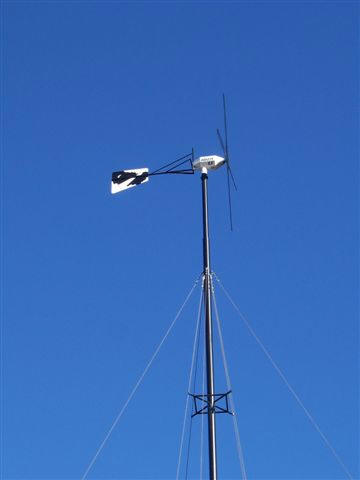
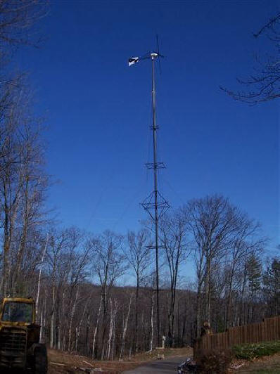
First Power!
As to be expected, there was no wind
the first day we raised the turbine. On Thursday morning I turned the unit on
just to see it spin slowly in the wind. An hour later I walked outside and heard
a strange noise. Looking up, the generator was spinning nicely and the unit was
making electricity. The local code commission inspected my unit that day and it
passed. I am scheduled for the WE Energies "Grid Tie Inspection" next week. I'll
post electrical generation results, as I monitor it, in the future.
Update: November 20, 2008 -- Tom
reports that the final inspection went fine, and that the turbine was
generating 3300 watts during the inspection.
Wow!
Tom November 15, 2008