
Search
The Renewable Energy site for Do-It-Yourselfers
A Solar Water
Collector Made From CPVC
|
This was a quick prototype and test
of a solar flat panel collector using water as the heat transfer fluid.
The collector was constructed from CPVC plastic pipe. Radiant floor heat
transfer plates were used to absorb the solar energy and transfer it to the CPVC
pipe (see pictures). The collector is a small (5 sqft) size just to test
the concept. It is glazed with a single layer of PVC glazing from SunTuf
(see note below on this).
As an alternative to using the
(somewhat expensive) extruded alum fins, here are some homemade jigs to make
your own from sheet alum. Jigs. |
|
Construction:
The good news on this collector is
that it is dead easy to construct. It probably took less than an hour to
put the whole thing together.
-
Cut CPVC tubes to length (the
ratcheting scissors cutters they sell for this make this 5 seconds a cut)
-
Solvent weld the serpentine pipe
string together (fast and easy)
-
Put a bead of sealant in the
radiant floor heat spreader (to improve the thermal bond)
-
Tap the CPVC pipes into the radiant
floor heat spreaders
-
Paint the alum heat spreaders black
-
Build the box for the collector and
insulate the inside with Polyisocyanate type insulation.
-
Attach the glazing.
It could not be simpler.
Price:
The CPVC pipe and fittings are cheap.
The radiant floor heat spreaders that I used were fairly expensive, but there
may be cheaper ones out there, or it may be possible to fabricate them from
sheet aluminum.
Performance:
The performance graph and comments on
the performance are provided below.
Life:
The life of the collector is somewhat
doubtful. The temperatures in the stagnated collector are at or perhaps a
bit beyond the upper range of CPVC's rated capability. The fact that the
collector loop need not be operated at a high pressure probably helps.
Mounting the collector on a vertical wall where it would get less radiation
during the hotter summer period would also help. Covering the collector
with shade cloth in the summer would also help (this is actually recommended by
some commercial flat plat collector makers who make copper and glass
collectors).
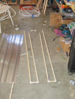
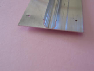
Assembling the serpentine CPVC pipe
run. The alum extrusion radiant floor heat spreader.
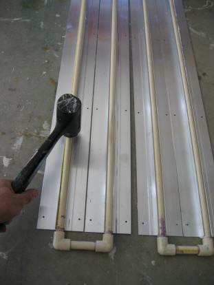
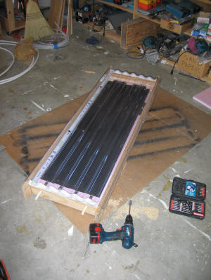
Tapping the CPVC into spreader
grooves. The finished collector.
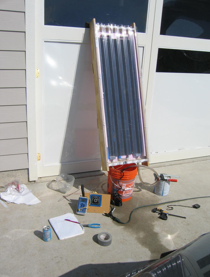
The performance test setup.
Tilt was set to give normal incidence around solar noon.
Performance on a sunny day.
The temperatures plotted are:
Water inlet temperature (blue)
Water outlet temperature (red)
Collector air temperature near the
top (black) -- located in shaded spot at top of collector box.
Ambient temperature (green) -- badly
located.
Note that the ambient temperature
sensor was badly located and are invalid. The actual ambient temp was 62 F
at 11:20 am, rising to 77 F at 2:53pm.
This plot shows the performance for
the CPVC collector on a sunny day. There were intermittent thin high
clouds for part of the afternoon.
The collector was heating about 4.5
gallons of water from an uninsulated bucket. The flow rate at which water
was pumped through the collector was 0.5 gpm.
I also mounted thermocouples on the
radiant heat spreader fin with the following typical results:
T fin at outer edge
151 F
T fin near CPVC pipe
147 F
T of outer wall of CPVC pipe
103 F
T fluid
100 F
There is a big
temperature drop between the fin and the fluid (i.e. a high thermal resistance).
Most of this temperature drop appears to be taking place between the fin and the
CPVC pipe. Apparently there is not a good thermal bond between the CPVC
and the radiant heat spreader. This is in spite of the fact that the alum
heat spreaders are a very snug fit on the CPVC and there is silicone in the
groove.
I estimated the efficiency of the
collector by calculating the energy out from the flow rate and the inlet and
outlet temperature, and the energy in from the midday solar radiation at my
latitude and tilt. This came out to 60% -- I was surprised that it
was this good. And, 5 sqft of collector managed to heat about 4.5 gallons
in an uninsulated bucket to about 125F -- not so bad -- I am sure it would have
achieved a significantly higher temperature if the water storage bucket had been
insulated (you can see from the performance graph that the collector continues
to add heat to the bucket through the whole afternoon, the bucket is just losing
more heat than it is gaining due to no insulation).
If the thermal bond between the pipe
and fin were good, the fin temperature would drop down closer to the fluid
temperature. The fins would not run so hot, and would not lose so much
heat out the glazing. The efficiency and heat output would improve.
If you assume that for a good thermal bond that the temperature of the fins
would drop by 40F, and that the glazing is R1, then the gain in efficiency comes
out about +13% for a well bonded fin and tube. So, it appears that you do
take a pretty good hit for this construction.
Note on PVC glazing: I would
normally have use Polycarbonate glazing, but I had the PVC on hand and used it.
By the end of the test, there was an about 4 sqinch area near the top of the
glazing that had been permanently deformed by the heat. I would not
recommend using PVC in this application. Polycarbonate glazing
is good to about 270F, and should work OK.
Note also that I used the "pink" foam
board insulation because it was on hand. Polyioscyanate insulation should
be used because of its higher temperature capability.
Overall, I guess you have to weight
the time and cost savings against the poorer performance and shorter life.
I can't rule out the possibility that the life might be a lot shorter.
Gary
9/8/05
Some Additional Notes On CPVC vs
PEX:
It was pointed out to me by Burt M.
that PEX has a greater thermal conductivity coefficient than does CPVC. He
suggested that 1) most of the temperature drop may be in the CPVC wall (rather
than the thermal bond between the fin and CPVC), and 2) that PEX might work
better due to its higher thermal conductivity.
I am inclined to think that Burt is
correct on both points -- here are some tentative calcs to support this:
I had a go at calculating the theoretical temperature drop across the
CPVC tube wall using the the thermal conductance values you provided
above. If I did the math right (see below), then it takes a delta T
of about 26F to transfer the incoming heat from the fin (and sun)
through the wall of the tube. So, this says that about 65% (26F/40F) of
the
thermal resistance seems to be in the CPVC wall.
The PEX tubing I have has the same OD and ID as the CPVC, so the PEX
might be 2.1/0.9 = 2.3 times better, or about 11F to transfer the heat
through the PEX wall.
This says that PEX would do somewhat better than CPVC.
The wall heat transfer calc:
About (290 BTU/sqft-hr)(0.6 efficiency) = 174 BTU/sqft-hr gets to
each sqft of fin and is transferred into the fluid in the tubing.
Each sqft of fin (4 inch wide) is served by 3 ft of pipe.
CPVC half inch pipe: r2 = 0.3875 inch, r1 = 0.3125 inch
Ucpvc = 0.9 BTU-in/ft2-hr-F = 0.075 BTU-ft/ft2-hr-F
The transfer through the CPVC wall is:
q = UA(Touter - Tinner)
UA = (2*Pi*L*K)/ln(r2/r1)
UA = (2)(3.14)(3ft)(0.075 BTU-ft/ft2-hr-F)/(ln(0.3875/0.3125)
= 6.6 BTU/ ft2-hr-F
(Touter-Tinner) = q/UA = (174 BTU/sqft-hr)/(6.6 BTU-ft/ft2-hr-F)
= 26F
Since the PEX has about twice the thermal conductivity of CPVC, and the OD
and ID are the same, the temperature drop across the PEX wall would be less than
half as great.
Source for thermal conductivities:
CPVC at
http://www.boedeker.com/pvc_p.htm. (and many other plastics --
a good ref)
This gives a thermal conductance of 0.9 BTU-in/ft2-hr-F.
Compare this with aluminum at about 1500, or copper at 2700!
PEX tubing thermal conductivity: 2.43 BTU in/hr-ft^2-F per DIN52612
http://www.viega-na.com/downloads/1201700887SP-11108-1106%20Pextron%20Tubing.pdf
Apparently PEX has significantly higher conductivity than CPVC.
PEX-AL-PEX is even better.
Gary
09/11/05, April 4, 2008