
Search
The Renewable Energy site for Do-It-Yourselfers
Flow Organizer Solar Collector Test
|
This prototype of a window size solar collector with a
“flow organizer” grew out of an internet discussion on how to prevent excessive
heat buildup between an insulating window shade and the window glazing. Nick
Pine suggested that making the shade into some form of solar collector would
keep the heat from building up, and provide some useful heat to the living
space. Version one of this combined window shade and solar collector is here:
http://www.builditsolar.com/Experimental/ColShade/colshade.htm. Nick further
suggested that a version of the collector with a flow organizer might work
better than version one, which is a straight through thermosyphon collector.
This is a first cut at a flow organizer version of the window collector.
The results for a basic collector with flow organizer, and
the results of applying three refinements to this configuration are show below
in the “Test Results” section. The Flow Organizer collector appears to do quite
well. |
|
Solar Collector with Flow Organizer:
Most thermosyphon air collectors have an inlet at the
bottom and an outlet at the top. Cool room air enters the bottom, rises up
through the collector, heats up as it passes through or along the absorber, and
exits out the top vent.
This collector has a “flow organizer” that allows the cold
air inlet and hot air outlet to be positioned at the top of the collector. The
cold air passes between the aluminum sheet outlet vents and flows to the south
side of the collector (see picture). It then flows down the glazing, and
through the screen absorber, as the absorber heats up the flow, it rises up the
north side of the collector and exits out the aluminum outlet vents. The flow
organizer allows the cold flow to pass through the hot flow, and thus to flow
down the glazing. Having the cooler air flow down the glazing increases the
efficiency of the collector, by reducing losses. It also might be more
effective in preventing backflow at night.
There is a good description of the flow organizer on David
Delaney’s web site here:
http://davidmdelaney.com

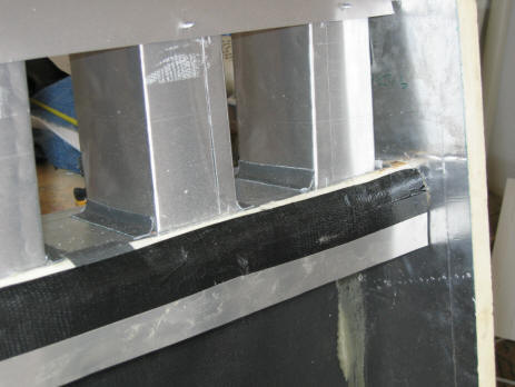
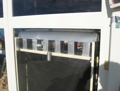
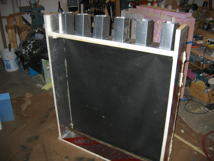
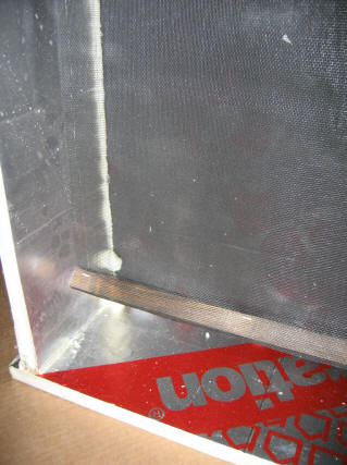
Flow organizer collector prototype viewed from the south
(sun side) without glazing. The rectangular aluminum ducts are the outlet
ducts. The cool incoming air flows through the gaps between the ducts, and then
down the glazing. It’s hard to see, but the absorber is a layer of window
screen suspended about midway back in the collector. The ¾ by ¾ piece of wood visible
near the bottom of the collector anchors the bottom of the absorber screen.
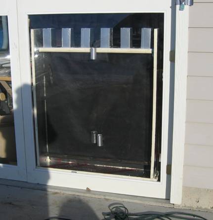
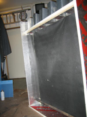
The flow organizer collector in position against an
existing piece of glazing.
The picture is taken outside, and is looking north (this is what the sun sees).
The 3 small aluminum cylinders shield the temperature sensors from direct
sunlight so that they can sense the air temperature (does anyone have a better
way shield the temperature sensor?).
Description:
Geometry:
Inside height from bottom to flow organizer shelf = 40.5
inch
Inside width = 40 inches
Height above flow organizer shelf = 6 inches (without flow deflector)
Collector area = (40.5 + 7)(40)/144 = 13.2 ft^2
Inside depth = 7 inches, 3.5 inches front of absorber
screen, and 3.5 inches behind screen
Inlet:
Inlet slot just north of glazing is 2 inches deep by 40 wide. Area = 80 sqin
Outlet:
6 outlet ducts at 3 inches wide by 4 inches deep. Area = 72 sq inches
The outlet ducts extend 6 inches above flow organizer shelf.
Temperature sensors:
There are 4 logged temperature sensors in collector.
All but the outlet temperature sensor are visible on the picture above.
Outlet temperature – centered in middle outlet duct.
Inlet temperature – in the inlet slot flow near middle of
collector and just below the flow organizer shelf. It is protected from the sun
by a 2 inch diameter alum cylinder.
Lower collector temperature sensors
Two temperature sensors are located about ¼ of the way up
from the bottom of collector.
One is just north of the glazing and the other is between
the absorber screen and the back wall.
Both of these sensors are protected from direct sun by aluminum cylinders.
Absorber:
The absorber is 1 layer of black fiberglass insect screen that is suspended 4
inches from the back wall (3 inches from the glazing). There is an open slot
of about 2.5 inches at the bottom of collector. Refinement 2 adds a 2nd
layer of absorber screen.
Walls:
The back wall of collector is 1 inch Polyiso insulation board, and is painted
black on the inside.
The other walls and bottom are Polyiso board without
paint. They are faced with aluminum foil.
Test Results --A base configuration and 3 variations on it were tested.
The table below gives a summary of the results.
Base Collector: has one layer absorber screen, no
flow deflector, square edge on inlet flow
Variation 1: added a deflector that was aimed at
deflecting the flow from the outlet ducts into the room. The deflector did seem
to increase the output noticeably (+15% ish). I’m a bit at a loss to explain
why this made so much difference.
Variation 2: added a 2nd layer of
absorber screen. This actually appears to lower the output. The flow rate is
down, and the delta T from inlet to outlet is about the same.
Variation 3: added rounding of the corner on the
flow passage into the inlet slot. That is, rounding the south edge of the flow
divider shelf. The area of the inlet slot was not changed, but instead of
having a sharp corner where the air turns down into the inlet, it was rounded
off. This does not appear to make much difference. It actually shows a slight
reduction in output, but I think that is just the error margin in the test
setup.
The night measurements seem to indicate that not much air
is flowing through the collector, which would be good. I could not detect any
flow velocity, but I can’t really read any less than about 60 fpm. Smoke would
be nice.
Results Table
|
Parameter |
Base
(1) |
Add Deflector (2) |
Add 2nd Screen
(3) |
Round Inlet Lip
(4) |
Night
(5) |
2/01/06 Dave's
Changes |
2/10/06 2nd with
Changes |
|
Time |
10:00 am |
11:30 |
12:24 |
12:56 |
12 midnt |
11:02 |
11:41a |
|
Tambient |
33F |
38 |
40 |
40 |
? |
42 |
30 |
|
Troom |
63 |
69 |
73 |
76 |
? |
70 |
64 |
|
|
|
|
|
|
|
|
|
|
Tinlet |
75.5 |
88.1 |
92.9 |
91.8 |
42 |
91.0 |
87.1 |
|
Tglass side ¼ up |
95.4 |
111.1 |
127.6 |
123.2 |
28 |
|
98.0 |
|
Tback side ¼ up |
91.3 |
114.7 |
112.7 |
110.9 |
30 |
|
110.1 |
|
Toutlet |
107.0 |
124.3 |
129.2 |
126.8 |
47 |
121.6 |
117.8 |
|
Tglaz(10) |
|
97/78 |
109/84 |
101/76 |
|
|
|
|
|
|
|
|
|
|
|
|
|
Voutlet |
90 fpm |
100 |
90 |
90 |
|
105 |
100- |
|
Vinlet |
70 fpm (9) |
80 |
70 |
75 |
|
85 |
80 |
|
Sun |
18500 lum/ft^2 |
20500 |
21000 |
20500 |
0 |
20500 |
21500 |
|
|
|
|
|
|
|
|
|
|
Tout-Tin |
31.5F |
36.2 |
36.3 |
35 |
5 |
30.6 |
30.7 |
|
Qout |
1897 BTU/hr |
2422 |
2186 |
2108 |
0? |
2150 |
2054 |
|
Qout adj |
2153 |
2481 |
2186 |
2160 |
|
2203 |
2006 |
|
Qout/sqft |
163 |
188 |
166 |
164 |
|
170 |
154 |
Configurations:
(1) Base
configuration as described in the geometry section above. One absorber screen.
(2) As above, with
added alum sheet deflector that deflects the heated flow from the outlet ducts
toward the room (see picture).
(3) As above, with
another layer of window screen added to the absorber – 2 layers total.
(4) As above, with
the south edge of the flow divider shelf rounded to improve inlet airflow.
(5) Same as
configuration 4, but run at night.
Base Configuration Energy out (Qout) was calculated as:
Qout = (107F – 75.5F) (0.715 ft^2)(90 ft/min) (60
min/hr)(0.065 lb/ft^3) (0.24 BTU/lb-F)
= 1897 BTU/hr
Adjusted Energy Out (Qout adj) is the energy out adjusted to the highest sun
level of the test. This is an attempt to compensate for the fact that sun
level varied throughout the test. Sun level was measure with an Onset light
intensity logger, which gives light intensity in lumen per sqft. It does not
measure the full solar spectrum, but does give some idea how much the sun varied
(see plot below).
Update 2/14/06:
This test incorporates the changes suggested by David.
The changes are:
-
Add a vertical flow divider that extends vertically down 2 inches from
the edge of the horizontal flow organizer shelf.
-
Move the absorber toward the north (now 3 inches from back and 4 inches
from front)
-
Terminate the absorber 5/8 inch below the bottom of the flow organizer
shelf
-
Suspend the absorber from a horizontal wire such that the top of the
absorber does not have a “fat” support that impedes flow.
-
Also went back to one layer of absorber screen, since this seemed to work
better in earlier test.
-
Dave’s drawing below:
Pictures with the changes:
Vertical flow divider added.
I am wondering if I should have used a light colored tape?
The tape gets hot the touch, and may be discouraging the downward airflow at the
inlet by heating it to early?
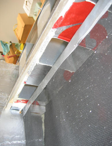
Looking up at top of absorber, and into the outlet ducts.
The absorber has been moved north a bit, and the thick member at the top of
absorber replaced by a suspension wire with tape over it.
Single absorber screen.
How did the Flow Organizer Collector compare with
others:
A VERY rough comparison of the outputs of several air collectors:
The Collector Shade concept (1) 100
BTU/sqft-hr
The Organized Flow collector 190
BTU/sqft-hr
The Garage Thermosyphon collector(2) 230
BTU/sqft-hr
(1)
shade converted to thermosyphon collector:
http://www.builditsolar.com/Experimental/ColShade/colshade.htm
(2) My workshop
thermosyphon heater:
http://www.builditsolar.com/Projects/SpaceHeating/solar_barn_project.htm
It may be unfair to compare the garage collector to the two window collectors,
as it has the advantage of a 7 ft rise from inlet to outlet.
From outside with aluminum sheet flow deflector in place.
It deflects outlet duct flow into room.
With the inlet lip of the flow divider shelf rounded off to
allow smoother flow into inlet slot. It turns what was a square edge into
a half cylinder. It actually looks better than the
picture. Looking northwest. Screen absorber starts just below the
white south edge of flow divider shelf.
Odd stuff:
It seems odd that the collector inlet temperature was so much higher than room
temperature. Typically there was an about 20F difference between room temp and
the sensor that measured the temperature right at the top of the inlet slot. Is
the inlet air getting warmed by the outlet ducts or air before it gets to the
inlet slot? Or, is the temperature sensor not getting a good reading? The
area of the inlet temp sensor is in sunshine. I surrounded the temp sensor with
an alum sheet cylinder to shield it from the sun – maybe the shield is not
effective? Any ideas on this?
I added the flow deflector to see if that would decrease
this difference between room and inlet temperature, but it actually increased
it, and also increased the output – odd.
Looking at the temperature sensors that were located about
¼ of the way up from the bottom of the collector. One is near the glazing, and
the other half way between the absorber screen and the back (north) wall. On
most of the tests, the front sensor reads higher temps than the back sensor.
This seems like the wrong way round?
Both of these sensors are in the sun, but are shielded by
the same kind of cylindrical alum shields described above. Any ideas on this?
Adding the 2nd layer of window screen absorber seems to increase this
effect.
Cautions:
I have to say this was a start, but not done to the level of precision I
would like, and I think the numbers should be used with some caution. It would
be nice to do more of a side by side comparison under exactly the same sun
conditions, and I am not sure I believe that the temperature sensors in the flow
organizer collector are measuring the actual air temperature even with the
shields. I pass the results on because they seem interesting, and maybe someone
will want to take this further, or make some suggestions on how it could be done
better.
2/14/06 -- after playing around some more with the
temperature sensors, and doing some additional measurements with a shaded
thermocouple on a stick that I could move around from place to place, I feel
better about the temperature sensors getting fairly accurate data for both of
the tests.
Gary
1/28/06
Updated 2/14/06
Data Logger Plots:
Configuration 2 -- Base configuration with outlet
deflector added:
Configuration 3 – outlet deflector + 2nd
absorber screen:
Sun Intensity:
Update 2/14/06 -- logger plot for the flow organizer
with Dave's suggestions incorporated:
2nd Test with changes 2/10/06
Some Construction Pictures:
Geometry:
Overall height
48 inches
Height from bottom
to flow organizer shelf 42.5 inches (40.5 inches inside)
Overall width 42
inches (40 inches inside)
Overall depth 8
inches (7 inches inside)
Depth of cold air
entry slot 2 inches
Window screen
divider is 4 inches for the back (north) face and 3 inches form the front
(south) face.
Area of downflow
channel = 40*3 = 120 sqin
Area of upflow
channel = 40*4 = 160 sqin
Upflow vents (hot
air exit) -- 6 total at 3 inches wide (E-W) by 4 inches deep (N-S) -- 6
inches tall.
Upflow vent area =
(3*4*6vents) = 72 sqin -- about 50% of upflow channel XC
Slots between the
upflow vents (where cold air enters) are 3.66 inches wide.
Area between
upflow vents = 5* ( 2*1.83 + 5*3.66) = 110 sqin -- about 90% of
downflow channel XC
Sides, bottom, and back are made from
1 inch Polyiso board with alum foil faces. South face of back wall is
painted black using barbeque paint. Glued together with "great
stuff" PU foam.
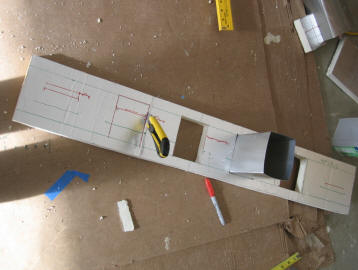
The flow divider board is also 1 inch
polyiso -- it has 6 rectangular holes of 3 X 4 inches each to accept the
alum upflow vents. The slots between the upflow vents are 3.66
inches wide.
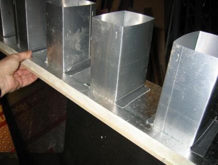
The upflow vents are made from light
alum flashing bent into rectangular 3X4 inch ducts. The ducts stick up 6
inches above the flow divider board after being pushed fully into the flow
divider board.
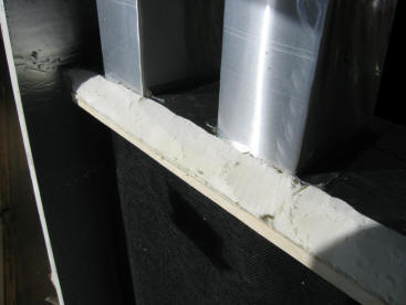
The vertical screen is one layer of
black fiberglass window screening. The top end is fastened to the flow
divider board at the S margin of the upflow ducts. The bottom is weighted
with a 3/4 by 3/4 wood piece, so that it hangs vertically. The bottom of
the screen is about 1.5 inches above the bottom of the enclosure.
My intent is to just push it against
one of the acrylic panels on my outer garage doors to test it.
I will put some of the Onset
temperature sensors in the up and downflow paths.
If the velocity if high enough, I'll
measure it with the Kestrel meter or the Testo stick.
It would be nice to have some way
(like smoke) to see the flow -- I have not had much luck with generating enough
smoke to be useful -- maybe you have an idea on this.
I did not glue in the ducts or the
flow divider board so that they could be changed easily.
Not sure what to do about the top lid
for the box (near the top of the upflow ducts) -- if anything?
I'll give it a try on the next sunny
day -- which may be tomorrow -- let me know if you have any ideas on things to
change or measure.
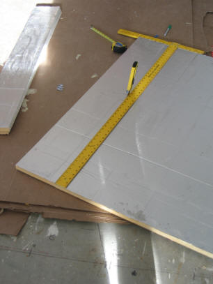
Flow divider board
Cut out with razor knife -- very fast
and clean
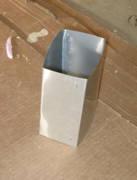
Upflow duct from alum flashing.
Upflow ducts taped to flow divider board.
Bottom of screen-- looking north.