Search
The Renewable Energy site for Do-It-Yourselfers
Test on Solar Collector
with Horizontal "Risers"
| Most collectors that heat water have a supply manifold along the
bottom and a return manifold along the top --these two manifolds are
connected by a bunch of vertical risers with heat absorbing fins
attached to them. Water flows in the supply manifold, up the
risers where the solar heat warms the water flowing in the riser, and
then into the return manifold to go back to the storage tank. It has
been suggested by
Alan Rushforth
that for some of the very wide collectors that DIYers tend to build for
space heating that an alternative in which the "risers" run horizontal (hisers?)
and the manifolds run vertically on the right and left might have some
advantages. The hiser collectors would use less material because
the manifolds are shorter, and it would have far fewer riser to manifold
joints -- these joints are expensive and time consuming, so cutting them
back is good. The horizontal risers might also result in a more
uniform flow distribution for the collector. Uneven flow
distribution can be a problem on large collectors, so a more even flow
distribution would be a plus.
This is a small test to take this horizontal
riser collector idea a bit further. |
|
In an earlier test, I took a cut at
measuring the
evenness of the flow distribution in my prototype copper pipe aluminum fin
collector by removing the glazing, and measuring the temperature rise along
each riser using an IR temperature gun. For this test, I turned the
same collector on its side so that the risers run horizontally and did a number
of temperature and flow measurements to see how the horizontal "riser"
arrangement works out -- thanks to Bob Allan for suggesting this idea.
In a nutshell, the hiser collector
looks promising to me, and (I think) deserves to be tried on a real, large
collector.
Directory of Tests
I did these tests
Fill up test...
Flow Distribution
with Normal Flow
Drain back
test...
Fill up test
with low flow...
Flow
Distribution with Low Flow...
Test Setup
The next few pictures show the test
setup.
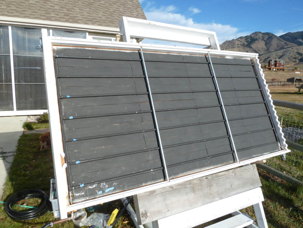
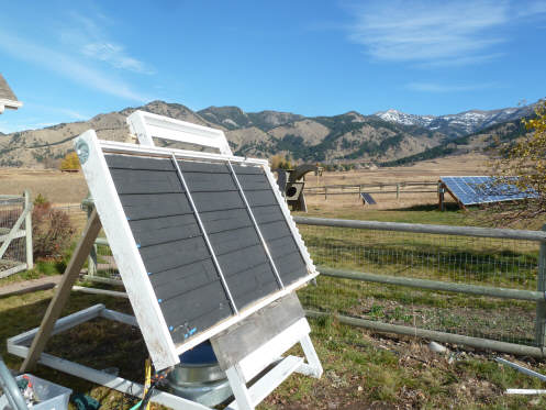
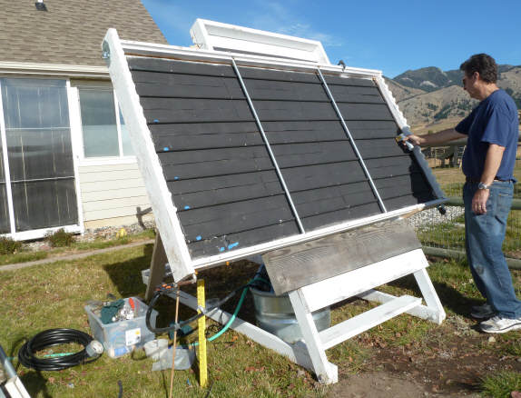
The collector is set up with the
riser nearly horizontal -- they have an about 1/4 inch per foot slope for drain
back.
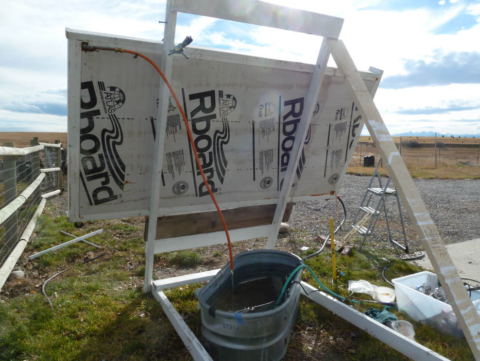
This is a drain back system.
The drain back tank is the galvanized stock tank. Water is pumped from the
tank with a submersibe pump to the lower left corner of the collector.
Water returns to the tank from a return line connected to the upper right corner
of the collector. A valve is included in the supply line to adjust the
flow rate.
|

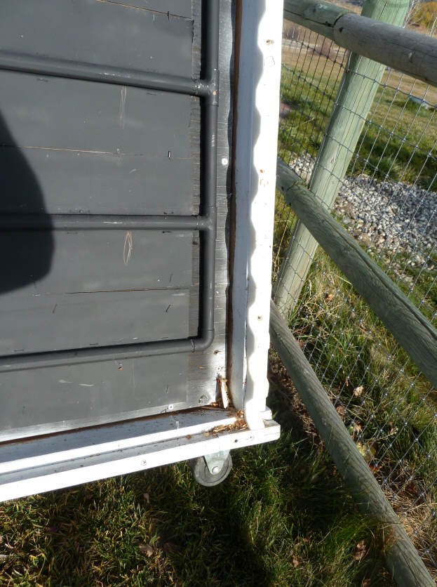
The prototype copper tube/alum fin
collector turned on its side for the test.
Note block of wood to provide
drain back slope. |
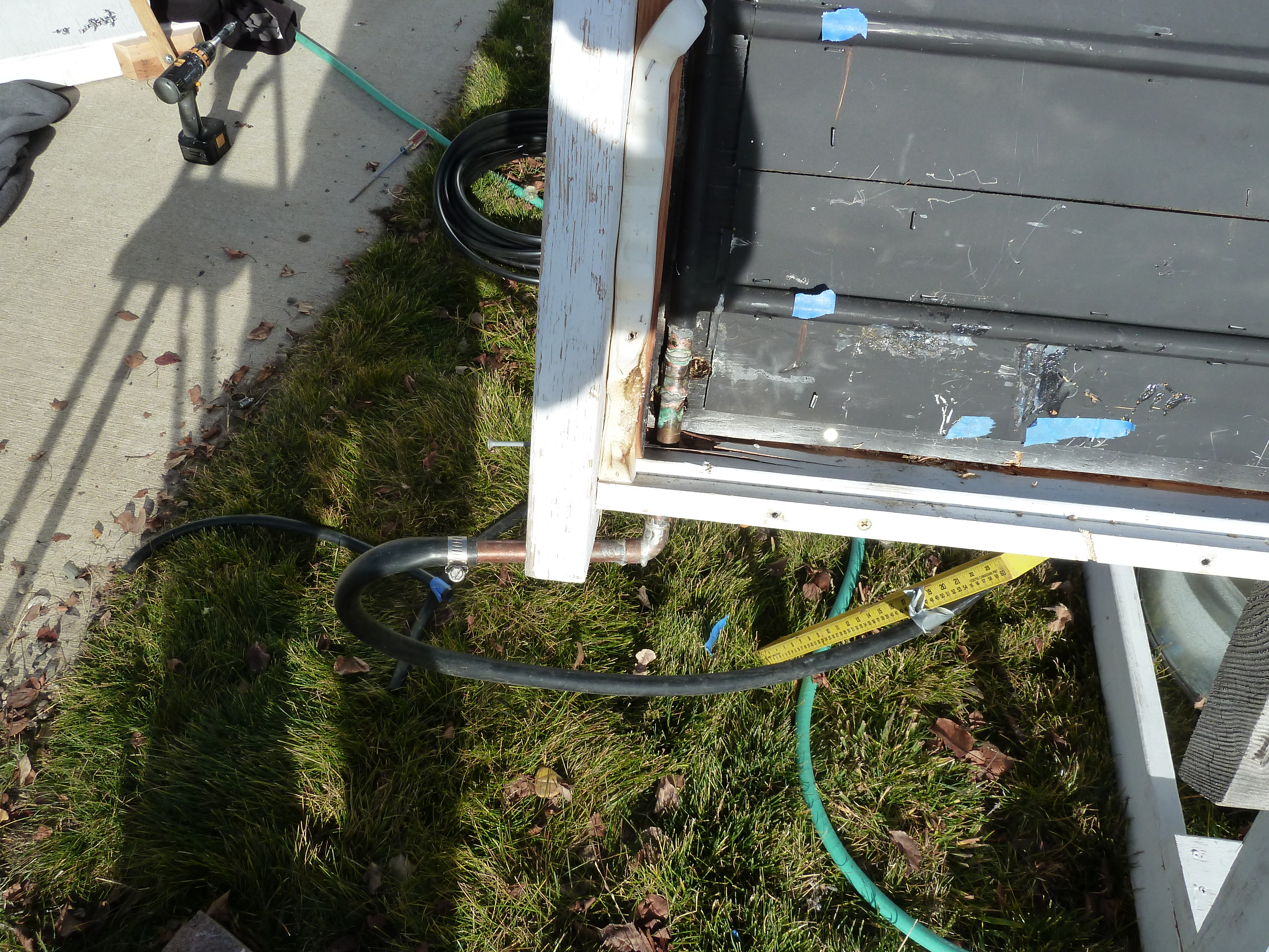
The black supply line goes from
submersible pump via valve to
lower corner of collector.
The orange PEX line is the return
line from top opposite corner of collector. |
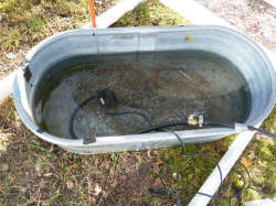
Submersible pump and supply line
with flow control valve.
The orange line is the return line
from collector to tank. |
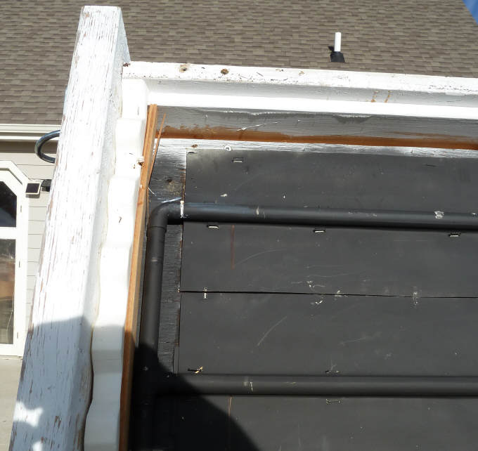
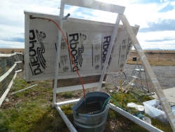
These pictures show the details of
the collector absorber grid construction.
Note that the 1) the manifolds are
only half inch pipe (same as risers), and 2) that elbows are used instead of T's
at the two corners -- these two features are not usual for collectors -- the
effects are discussed at the end.
The glazing was removed for the test
so that the IR temperature gun could be used to measure the temperature of the
risers.
The collector was installed such the
the hisers had a slope of about 2 inches total toward the supply end of the
collector for drain back.
Fill Up Test
This was just observing how long it
took for the collector to fill when the pump was turned on, and how the fillup
progressed.
The flow rate for this test was 1.25
gpm. This is about 0.04 gpm per sqft of collector, which I would call a
good, normal flow rate. See below for low flow rate test.
As you might imagine, the collector
filled from the bottom up, hiser by hiser. I could see the progression by
just measuring the temperature of the risers with the IR temperature gun.
So, first the lowest hiser temperature went down as water started flowing into
it, then the next one up, and so on until flow got to the top hiser. There
was no flow out the return line until the top hiser was getting water.
It took about 1 minute for the collector to fill up and start flowing water out
the return line.
Drain Back
Test
The drain back test was done by
turning off the pump, and disconnecting the supply line from the pump so I could
see the drain back flow. This probably results in a little faster drain
back since there is no pump resistance, but it makes it easier to see how its
progressing.
The drain back was without drama, and
took 1 minute 15 seconds. A nice uniform flow.
After all flow stopped, I blew into
the return line to force out any remaining water. The result was about
half a cup of additional water -- this seems OK to me.
It would be nice to compare it to the
same collector in the vertical position, and I'll do this if I get a chance, but
the drainback time seems about normal to me.
Flow Distribution
Test
The table below shows the
temperatures and temperature rise for each hiser.
Measuring hiser temperatures.
This is an average of 4 runs done
during very clear skies.
|
Left
Manifold |
Left side of hiser temp |
Hiser temp rise |
Right end of hiser temp |
Right
Manifold |
|
85 F |
7 F |
92 F |
|
86.5 |
10.3 |
96.8 |
|
81.3 |
20.8 |
102 |
|
82.5 |
21.8 |
104.3 |
|
83 |
28 |
111 |
|
81.5 |
14.8 |
96.3 |
|
74.5 |
20.3 |
94.8 |
So, for example, the 2nd hiser up
from the bottom has a left end temperature of 81.5F, a right end temperature of
96.3, and a temperature rise of 14.8F.
The temperature rises are reasonably
uniform indicating that all hisers are getting flow.
There is certainly no bottom to top
pattern of lower flow at the bottom risers or lower flow at the top risers as
one might anticipate could be a problem with the hiser arrangement.
The variations seem of the same order as I've seen on other flow distribution
tests.
The lower temp rise and higher flow
rate in the top riser is probably mostly due to the elbow at its right end
rather than a T.
Fill Up With
Low Flow
I adjusted the flow rate down to 0.68
gpm, or 0.02 gpm/sqft. This is lower that I think should be used on
collectors, but I was trying to see if it would result in problems for the
hisers.
The fill up went exactly as it did
for normal flow, but just took quite a bit longer. The hisers filled
starting with the bottom hiser, then next up, etc. until the top on filled.
At that point water started flowing out the return line.
This all took about 2.5 minutes.
Note that is was possible to adjust
the flow so low that the return line would not stay full -- in this condition,
the flow rate went down to a very low level because the without the return line
full, there was no pressure recovery to help the pump produce more flow.
So, this is something to look for, but its a problem not related to the hiser
configuration.
Flow
Distribution with Low Flow
I did a couple runs of measuring
hiser temperatures with the low flow.
The results were very similar to the
normal flow with somewhat higher temperature rises as one would expect with the
lower flow.
There was no indication that the
lower flow resulted in flow distribution problems for the hiser arrangement.
Rough Conclusions
More work could certainly be done on
this, but the test appears to support:
- The horizontal riser
arrangement results in a reasonably uniform flow distribution between the
hisers (about the same as when the collector is used in its normal vertical
position).
- The drain back with the hisers
sloped at about 0.25 inch per foot appears to work well and result in good
drain backs in reasonable times.
- The fillup is pretty much the
top to bottom process one would expect with no surprises.
The test collector is a pretty small
collector, and it would be nice to do this kind of test on a larger, wider
collector.
If I had any reservations about the
hiser arrangement it might be that as the hisers get longer, the drain back
might get less certain. I suspect that it would be OK, but it would be
nice to test how well a (say) 20 ft long hiser sloped at 0.25 inch per foot
drains.
Prototype Collector Anomalies
Its important to note that this
prototype collector has a couple features that are not normal and they may have
some effect on the results.
- The manifolds and risers are
both half inch copper pipe. Normally the manifolds would be
larger diameter (say 3/4 or 1 inch). The small diameter manifolds were
used to see if on a relatively small collector like this you could get even
flow distribution without the larger manifolds. The gain is that
building the absorber is very easy for a DIYer.
I'm inclined to think that the
small manifolds make life a little harder for the hiser collector, so if
normal (larger) manifolds were used, I think the results would be the same
or better.
- I plumbed the first and the
last riser to manifold joint with and elbow rather than a T -- this seemed a
sensible thing to do at the time, but the earlier flow distribution test
shows that the risers with the elbows get a bit more flow because of the
reduced flow resistance. So, use T's not elbows for all the riser to
manifold joints.
Gary Nov 6, 2010