
Search
The Renewable Energy site for Do-It-Yourselfers
Air flow distribution for a
horizontal solar air heating collector with screen absorber
|
There has been some discussion on the Yahoo SimplySolar group about
whether a horizontal collector with a screen absorber would show a bad
airflow distribution due to the tendency of the warmed air to rise as it
proceeds across the collector from inlet to outlet.
I decided to try a 4 by 8 collector that is usually used in the
vertical position in the horizontal position and see if IR pictures of
the glazing would show any problems with the underlying airflow pattern.
This is a 4 by 8 ft solar air heating collector. The absorber
is 3 layers of black aluminum window screen. The glazing is
twinwall polycarbonate.
I took IR pictures of the glazing as air was being flowed through the
collector with a blower. The idea is that the IR camera sees the
temperature of the surface of the glazing, but the glazing (to some
degree) reflects the temperature of the air behind the glazing.
|
|
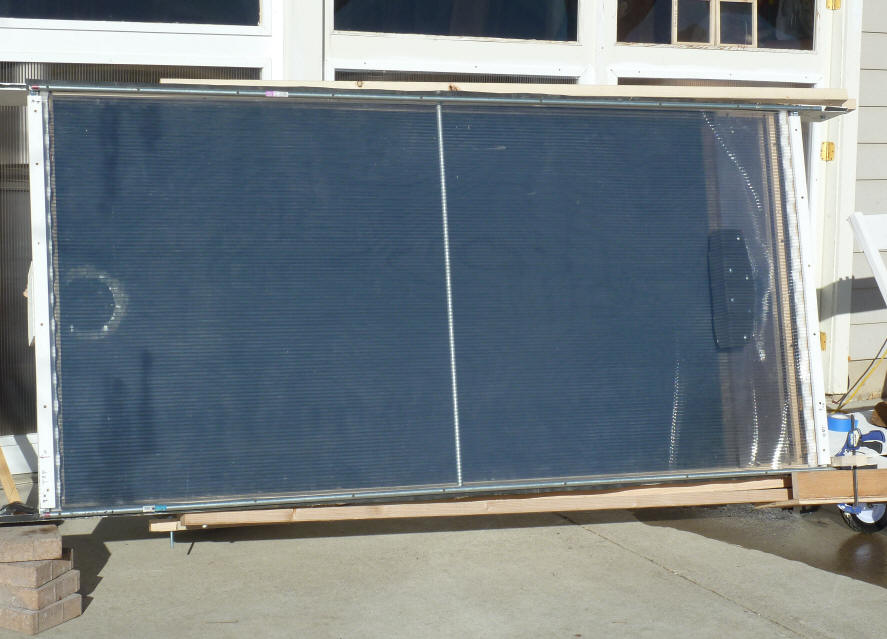
The collector set up horizontally.
The inlet is to the right -- there is a full width baffle made from twinwall
over the 6 inch circular duct lnlet to keep inlet air from blowing directly
against the glazing. The black metal baffle half way up is intended to
deflect some of the air outward to the top and bottom so that (ideally) there is
uniform flow over the full width of the collector.
The outlet is on the left -- its the 6 inch duct going out the back that can
be seen in the picture.
The screen absorber is 3 layers of black alum screen with a space of about
3/8 ths inch between each layer.
The screen is arranged such that the air enters on the glazing side of the
screen and has to flow through the screen to get out the exit, which is behind
the screen.
The test was done outside, so the inlet air was on the cool side.
The IR pics were taken with a FLIR I7 -- the temperature ranges were adjusted
for all pictures to show the range 40F up to 90F.
Horizontal Collector -- High Flow rate
In this first run, the air enters the inlet on the right at a relatively high
flow rate, and exits on the left.
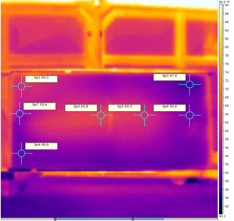
Tinlet = 51F
Toutlet = 76F
Flow rate = 980 fpm for 6 inch duct -- about 173 cfm with 90% velocity
profile correction, or about 5.4 cfm/sf
Remember that what you are looking at in all of the pictures is the outer
surface temperature of the glazing -- not the actual temperature of the air
flowing through the collector.
So, I'd say this shows little effect of the collector being horizontal.
There is a slightly warmer spot up in the upper left above the exit vent, but
its pretty small, and not that much hotter.
Horizontal Collector -- Normal Flow Rate
This run was done with a lower (more normal) airflow rate.
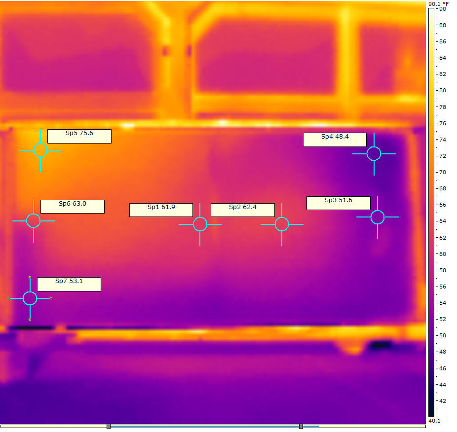
Tinlet = 47F
Toutlet = 87F
Flow rate = 550 fpm for 6 inch duct -- about 97 cfm with 90% velocity profile
correction, or about 3.0 cfm/sf
This shows higher temperatures on the glazing all over as you would expect
with the lower flow resulting in higher air temps through the collector.
The upper left corner hot spot appears somewhat larger, and there is more
temperature difference between this hot corner and the lower down area.
How serious a performance hit this upper warmer area is hard (for me) to say.
When the earlier version of the screen collector was run vertically, it had
spots in the upper left and right corners that ran hotter than the exit area --
so, this is not strictly a function of the horizontal orientation.
The performance penalty compared to a collector with perfectly even flow is
basically that the hotter glazing up in the upper left corner loses more heat
out the glazing to the air. As a rough estimate, if you said the hot spot
corner is 12F hotter than it would be with perfect flow (based on the temps in
the picture above), and the area of the hot spot is 6 sf, then the extra heat
loss through the R2 glazing is: (6 sf)(12F)/R2 = 36 BTU/hr --
this is quite small compared to the nearly 4000 BTU/hr that the collector might
harvest in full sun.
Its probably important to bear in mind that no collector achieves a perfectly
even airflow distribution, and some are certainly much worse than this
horizontal one judging from the IR pics of the glazing.
It may well be possible to work out some baffling that provides better
circulation to the upper left corner -- any ideas?
This collector is only 8 ft wide, so the effect may get larger (or not?) as
the width goes up.
I do plan to build a 2nd identical collector to this one, and at that point I
will probably run the two side by side with one vertical and one horizontal.
If you have any thoughts or comments, please lets hear them.
Gary
December 18, 2011