Search
The Renewable Energy site for Do-It-Yourselfers
$1000 Solar Water
Heater -- Storage Tank, Heat Exchanger, Pump, and Controls
|
The aims of the storage tank
are to provide: 1) a generous amount of solar heated water storage, 2)
not cost much to build, and 3) a have a long and boring life.
Providing a generous amount of storage
provides more reserve for cloudy periods, and gives the whole system
more thermal inertia so that the system is less subject to temperature
extremes -- e.g. overheating on a hot day with low usage, or exhausting
the storage rapidly with heavy use and/or cloudy weather.
The design of the tank is
very similar to the one used for the
Solar Shed
storage tank. It uses the same plywood box framed with 2
by lumber, lined with EPDM rubber sheet, and insulated with rigid foam
board.
Integrated with the tank is a
unique heat exchanger that is both inexpensive and efficient -- see
below. |
|
| Tank Directory:
|
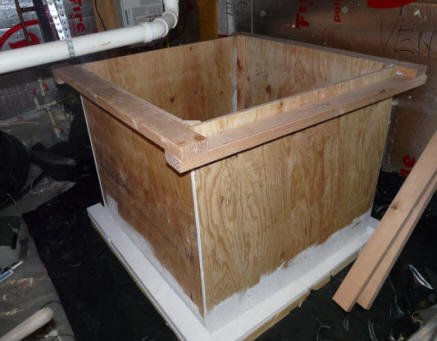
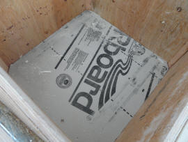
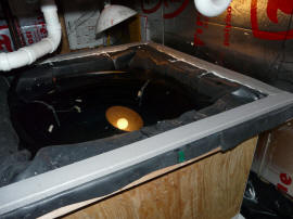
The storage tank in the crawl space before the insulation panels, EPDM
liner, and insulating lid have been installed. |
Pros and Cons of this Tank Design
It can provide large capacity
inexpensively. The larger capacity, well insulated tank improves system performance.
EPDM lined tanks have proven to
have a long life, and at the end of the liner life (15 years?), the EPDM
liner can be replaced at a cost of about $50, and you are good to go for
another 15 years.
The EPDM liner can handle
temperatures up to 180F+, although life is reported to be longer if the tank
is kept to 170F or below -- it should be really long at the 140F maximum
that this system operates at.
The tank can be made to fit in,
and make efficient use of limited spaces (in my case a limited height crawl
space).
AND, it can be built in pieces that fit into areas with limited access (such
as my crawl space).
The tank is unpressurized and
vented to atmosphere -- it can (and does) serve as both the hot water
storage tank and the drainback tank for the collector. This combined
functionality eliminates one more expensive item from the system.
The design allows you to use as
much insulation as you like to reduce heat loss.
The tank is large enough to allow
the use of a large coil of plastic pipe as the heat exchanger. This
makes for an inexpensive and essentially 100% efficient heat exchanger (see
details below).
The lack of any liner
penetrations below the waterline eliminates the possibility of leaks at
penetration points.
On the negative side, you need to
be certain that the tank sits on level smooth ground, and that it does not
sit in a puddle.
Its not as nice to look at as a
cool new stainless steel tank -- but, you could always have the kids draw
some artwork on it.
Locating and Installing the Tank
You want to place the tank on a flat,
level surface that is capable of supporting the weight, and that will not expose
the wood to wet conditions. Level flat dirt is fine. A crawl space
or basement if fine as long as moisture is controlled (as it should be for the
health of your house structure).
I have been asked about sinking the
tank into the floor, and on the Solar Shed Project I did this to some extent.
If the ground is dry, and you can isolate the tank from the ground (say with
insulation board), I think this is OK. I prefer the above ground
installation as you can be sure thinks will stay dry and you can inspect the
outside of the tank easily from time to time. For sunken or damp locations
you might want to consider using Medium Density Overlay (MDO) plywood, which is
very resistant to moisture, but costs about twice what ordinary plywood costs.
The other important consideration in
locating the tank is the relationship of the tank to the collector and the
relationship of the tank to the existing hot water tank or tankless heater.
This is a drainback system, so the tank water level MUST be below the level of
the bottom of the collector and below all the plumbing from the collector to the
tank. All of the water in the collector and in the plumbing from the
collector to the tank must drain by gravity when the pump is turned off.
The more direct and short this plumbing from the collector to the tank is, the
better. All of this plumbing must slope toward the tank.
The location should also be as close
to the existing hot water tank as is practical. Basically, the cold water
supply pipe that now runs to your existing hot water tank will be broken, and detoured
over to the solar storage tank and then back to the hot water heater. If
pipe going from the solar storage tank to the existing hot water heater is long,
the water in this pipe will cool off between hot water draws, and the solar
energy that went into heating it will be wasted. Its not the end of the world if you can't locate
them right together, but its desirable if you can.
Tank Construction
The finished tank is too large to fit
through my crawl space hatch. So, the tank parts are cut out, and a trial
assembly is done in the shop. It is then disassembled, and the pieces are
passed through the crawl space hatch. The final assembly is then done in
the crawl space. I assume in the sequence below that you will be faced
with a similar situation, and will have to take the tank apart after a trial
shop assembly -- if not, just go ahead and do the final gluing and screwing
right in the shop and move the assembled tank to where you want it.
Building the Tank Box and Frame
The tank walls and bottom are cut
from 3/4 inch exterior plywood. The top and bottom peripheral frames that
support the sides and hold everything together are made from good 2X4's.
As you build the tank, bear in mind that it will hold about 1500 lbs of water,
so work carefully, and pay careful attention to making good joints.
This is really simple carpentry, but it must be done correctly.
You can adjust the tank dimensions to
fit your space available and storage needs. Be sure to account for the
volume of insulation that you will be adding inside of the tank walls when you
make your tank capacity calculation. Another consideration in choosing the
tank dimensions is that if you plan to use the pipe coil heat exchanger
described below, you want the tank to be large enough to hold the pipe coil.
The dimensions I used are as follows:
- Base of tank is a
4 ft by 4ft half sheet of plywood -- this makes the the inside of the box
39.5 inches square (48 - 3*3.5 - 2*0.75 = 39.5 ) before any insulation is
placed inside. If you use 2 inch insulation inside the tank, then the
inside of the tank will come out just over 35 inches square with the liner
installed.
- The height of the tank walls is
35 inches. If you add 2 inches of insulation in the bottom, and allow
about 2 inches of airspace above the water, this gives you a water depth of
31 inches.
- The overall height with the lid
thickness and the insulation under the base is 41 inches.
- So, the volume of my tank is:
(35 inch)(35 inch)(31 inch)/ (231 in^3/gal ) = 164 gallons
None of this is at all critical --
within reason, you can change the dimensions to suit your space. If you
want to use the 300 ft coil of PEX heat exchanger (see below), then the inside
of the tank can't be a whole lot less than 35 inches across.
Click on pictures for full size
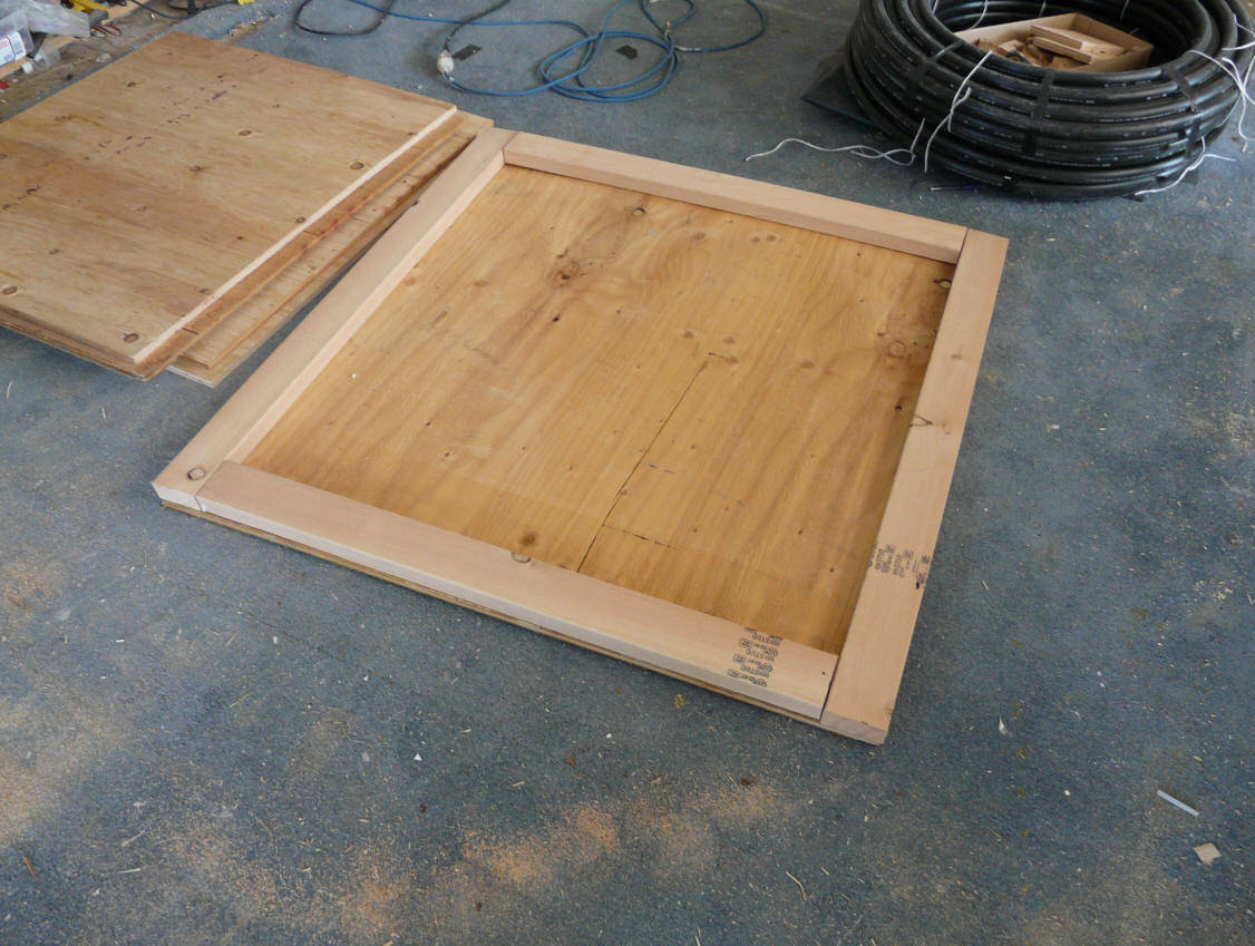
|

The tank base with the 2X4 perimeter
frame already in place.
The tank walls are to the left. |
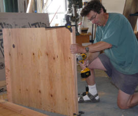
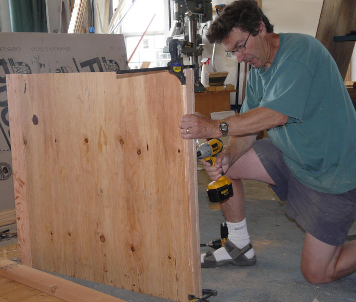
Installing the corner reinforcement strips
on one of the tank sidewalls. |
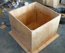
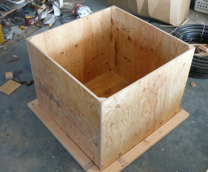
The tank sidewalls in place on the bottom frame. The top
peripheral frame
has not been installed yet. |
|
The bottom is cut out allowing sufficient space for the 2X4 frame that
surrounds the tank walls. The 2X4 edge frame is temporarily screwed
to the bottom. I made the bottom 4ftX4ft to make maximum use of the
plywood sheet.
The walls are cut out of the same 3/4 inch plywood.
Note the vertical corner reinforcement piece being installed. There is
one of these at each corner. While I made these pieces triangular, they
could be square, and it could be the same thickness as the insulation you plan
to install inside the tank.
|

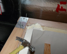
This shows the upper perimeter
frame being installed.
The 2X4's are lapped in this way
to provide a strong shear joint. |
This shows the final 2X4 installed
in the upper peripheral frame that
fills the gaps and provides a
flat surface for the tank lid to be
supported on.
(this taken after the tank is in the crawl space) |
The pictures above show the upper
perimeter frame. This frame supports the top of the tank walls, and
provides a flat surface for the lid to seal down on. Use 2X4's without a
lot of defects in them. The lap joint shown provides a good strong joint
which is needed to resist the water pressure.
The upper and lower peripheral frames
that support the tank sides are very important. They are resisting a lot
of water pressure -- the water in the tank weighs about 1500 lbs. The lap joints shown for the top
frame provide the needed shear area for a strong joint. This lap
joint results in the 2X4's on two sides being down 1.5 inches from the top -- to
make a level surface for the lid to seal down on, just add another section of
2X4 on these sides. Then add metal splice plates in the corners to
further strengthen these joints.
Tank Insulation
Next, the tank insulation panels can
be fitted.
Use polyisocyanurate insulation to
withstand the high temperatures that the tank may see. The polystyrene
pink, blue, or white insulation board will not stand up well to temperatures
over 130F, and should not be used. Many lumber yards carry polyiso
insulation, although they may not know it by that name -- ask to see the actual
sheets -- Polyisocyanurate will be spelled out somewhere on the sheet. The
polyiso is only a bit expensive than polystyrene, and in addition to be heat
resistant, it has a higher R value per inch.
I used 2 inches of polyiso insulation
inside the tank sides and bottom. This provides about R14.
Additional insulation can be added either inside or outside if that is not
enough. Using insulation inside the tank has the advantage that there is
no thermal bridging from the framework.
The tank sits on an additional 2
inches of polystyrene insulation in the crawl space.
The lid is insulated with 2 inches of
polyiso, plus a sheet of polystyrene over it.
|
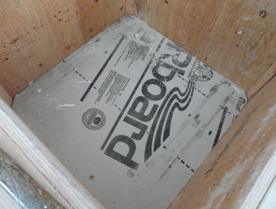
Bottom of tank insulation board
in place. |
This shows the sidewall pieces in place.
|
|
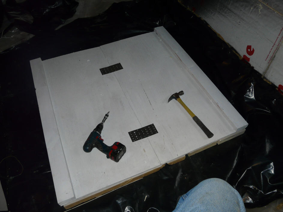
At this point, just cut the panels to
size and make sure they fit -- do not secure.
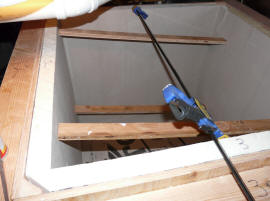
In my case, the bottom of the tank
was too large to fit through the crawl space access as one piece, so I cut it in
half and added metal splice plates to put it back together. NOTE -- don't
cut the peripheral 2X4 frame in half.
| |
The tank bottom cut in half to fit through
the crawl space hatch. The splice plates
will allow it to be put it back together.
Note that the bottom peripheral frame
2X4 is not cut in half. |
|
Giving everything a coat of paint at this point is also a good idea
Cutting Out the EPDM Liner
Cut the EPDM liner so that a single
piece can be used for the entire liner.
The liner dimension are about
2 * Sidewall Height + Bottom
Width + 10
For example, if the inside height
is 33 inches, and the bottom width inside the walls is 37 inches, then the
size of the EPDM piece is 2*33 + 37 + 10 = 113 inches.
If the tank is not square, then
bottom width will be different in the two directions, and the liner will be
rectangular rather than square.
Where these dimensions are measured
inside the insulation.
The 10 inches allows for the EPDM to
lap over the top of the insulation and the peripheral frame. This is
important, as the EPDM provides a sealing plane for the top to fit on.
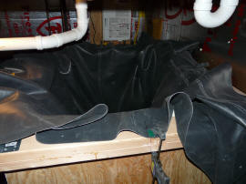
Lay your EPDM sheet out on a big flat
surface (like the lawn). Mark of the dimensions established above, then
check them, then check them again, then cut the EPDM with a pair of
scissors.
Before you fold up the EPDM, mark the
center of each side with a marker or tape. This make make it easier to do
the final installation in the tank. If the tank is rectangular, mark which
side is the longer one.
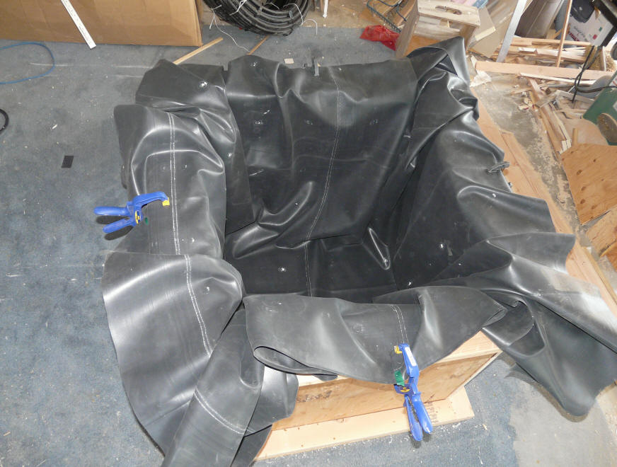
|
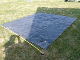
Measuring and cutting the EPDM |
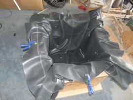
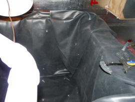
You can make sure the EPDM fits in the
tank, but leave the final folding until later.
This looks messy, but after all the loose material
is folded into one large fold at each corner, its fine. |
Move the Tank to Crawl Space
Now the tank can be disassembled and
move into the crawl space.
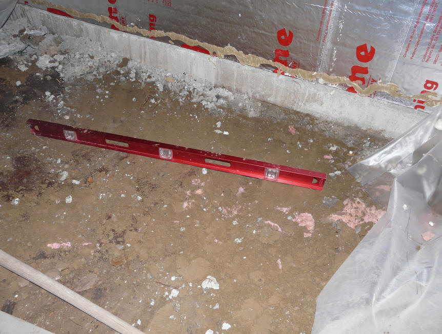
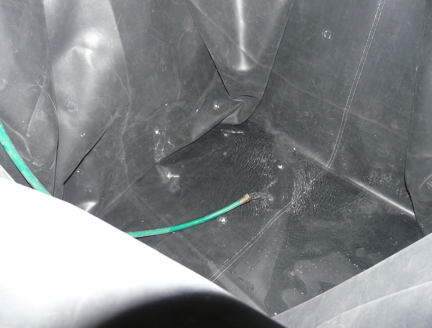
|
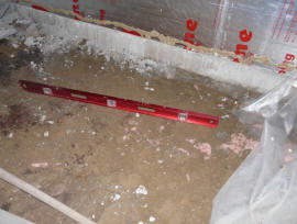
My crawl space floor.
Cut back the existing poly on the floor,
and level and compact the dirt to
make a good base. |
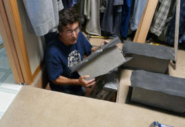
Down the hatch with all the parts. |

Install and seal down new 6 mil poly
in the tank area. Install the insulation
board over the poly. Splice the bottom
back together if you had to cut it in half. |
In my case, the crawl space has a
layer of 6 mill poly in place already. I cut this back to level the dirt
underneath and compact it. I then resealed up the existing poly with
caulk. I then added a new 6 mil layer of poly in the tank area. Then a 2
inch thick layer of extruded polystyrene is placed on top the poly. The
tank base goes on top of the insulation. This gives a dry,
level, and low heat loss surface for the tank to rest on.
If you had to cut the base in half to
get it through the hatch, then reattach the halves.
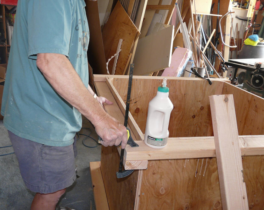
|
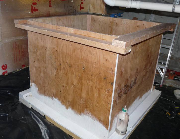
Glue and screw the components of
the tank together. |

Shows the tank structure nearly assembled
with glue and screws.
Just the final pieces of the upper perimeter
frame are missing. |
|
The pictures show the tank being
assembled in the crawl space.
Be sure you use glue and screws for
all the joints.
Our crawl space is so dry, I only
painted the bottom and lower sides, but it would be good to paint everything.
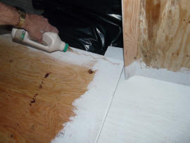
Installing the Insulation
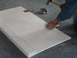
|

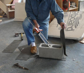
I secured the insulation to the tank
walls with some polyurethane foam
in the can (GreatStuff brand). The
pusher clamp and scraps of wood
keep the foam from expanding as it cures. |

Fill up any gaps and cracks with
the GreatStuff foam. Trim it back
after it cures.
|
Once you get the tank box assembled,
re-install the insulation panels. I glued them in place using the
polyurethane foam in a can. Be careful with this stuff in that if you get
in on your skin you will be wearing it for a week.
Fill up any remaining cracks and gaps
with more foam in a can.
Installing the Liner
Next, install the EPDM liner that you
cut out earlier.
Mark the mid points of each side of
the wood upper tank frame with a marker.
Push the liner into the tank, and
line up the mid points on the EPDM liner that you marked earlier with the mid
point marks on the frame. If you have rectangular tank, make sure you get
the long side of the liner with the long side of the tank. Clamp the liner
mid points to the tank sidewall midpoints.
Push the liner down to the bottom of
the tank. Then, take your shoes off, and work from inside.
This will look like a real mess when
you start, but just work all the excess material into a single fold at each
corner. Some clamps are helpful to keep things in place. Make sure
that there is enough slack in the EPDM that it won't be stretched by the water
pressure -- you want the liner to bear against the tank wall everywhere -- no
bridging. There will be fold lines in the EPDM -- this is OK. When
you get things in place, climb out of the tank, and put about half a foot
of water in -- then work the EPDM around and make certain that the EPDM is
supported by the tank walls and bottom with no bridging.
|
Line up the midpoints of the side walls with
the mid points you marked on the
EPDM sheet, and clamp. |
Work the excess material into on big
fold at each corner.
Clamp or tape things in place at
the upper perimeter frame. |
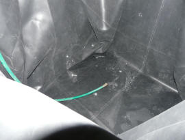
Add about 6 inches of water, and
make sure that the EPDM is flat
against the sides and bottom. |
Once everything is the way you want
it, run a bead of silicone between the EPDM and the top frame, and then staple
around the top edge with stainless steel staples.
At this point, you want to install an
edge board all the way around the ledge on the top of the tank. The board
holds down and seals against the tank liner you just installed, and provides a
flat plane for the lid to seal against. I have been using the
plastic deck boards that lumber yards sell for this. It seems to hold up
to the warm hot conditions inside the tank much better than wood.
Before installing the edge board, use
some scraps of EPDM to even out the top surface of the EPDM all the way around
the top of the tank. The folds that you put in the tank will mean that in
some places you have 3 thicknesses of EPDM lapped over the top ledge of the
tank, and in other places there is just one layer. Use the scraps to even
this up. Apply the scraps with silicone caulk.
Once the surface of the EPDM covering
the top frame of the tank is fairly even, put a bead of silicone around the top
frame, then screw the edge board down over the silicone and EPDM. Use
either stainless steel screws, or coated deck screws to prevent corrosion.
The two ends of the heat exchanger
coil (see below) will exit the tank trough openings you cut in this edge board
later.
|
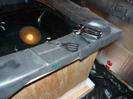
This shows the fillers made from
scrap pieces of EPDM used to
make the surface under the edge
board flat. |
This shows the edge board installed and
sealed down to the tank top frame.
The edge board is a plastic deck board. |
Heat Exchanger
The heat exchanger for this solar
water heater is a 300 ft coil of High Density Polyethylene (HDPE) plastic pipe.
This coil of pipe is immersed in the storage tank. Cold water
bound for the hot water tank first passes through the HDPE pipe coil where it
picks up the stored solar heat in the storage tank. If the water needs
further heating, the hot water tank tops it off.
The HDPE pipe coil itself holds 12
gallons of water. So, for each new hot water demand, there will be 12
gallons of water already in the pipe coil that has been heated up to the full
temperature of the storage tank. So, for the first 12 gallons of
demand, the heat exchanger is essentially 100% efficient. If more
than 12 gallons is needed, then the 300 ft pipe coil acts as a conventional heat
heat exchanger and the outlet temperature will drop somewhat below the storage
tank temperature depending on the flow rate. I have not had a chance to
test how much the temperature drops, but based on previous tests with smaller
coils, I believe that the performance will be good.
Since most hot water demands are less
than 12 gallons (showers, dish washing, ...), the heat
exchanger will be 100% efficient with water delivered at the full temperature of
the storage tank. Pretty nice for a $70 heat exchanger.
Using HDPE pipe here is pushing the
envelope somewhat in that it is not designed for handling high temperature water
at high pressure. This is one reason that the tank temperature is limited
to 140F. If you have high water pressure, you will want to consider
changing the pipe coil to PEX as discussed below.
If the use of the HDPE poly coil
makes you uncomfortable, or you have high water pressure that might exceed the
HDPE ratings at high temperatures, then you could use a coil of PEX. Here
is one outfit that has a potable water rated coil of 1 inch PEX for $170
http://www.blueridgecompany.com/radiant/hydronic/453/rht-radiant-pex-b
with free shipping! :) It would also be possible to use a shorter or
smaller diameter coil without compromising performance significantly.
Even if you use PEX for the heat exchanger coil, I favor keeping the maximum
tank temperature down to the 140F area. This (usually) eliminates the
need for an anti-scald (tempering) valve, and generally makes the life easier
for the tank liner and pump.
| |
Important Update on Pipe Coil Heat Exchanger
I have changed the HDPE pipe coil heat exchanger to use a coil of PEX
instead, and I think that this is the better way to go for most people.
All the details on why to use PEX instead of
HDPE and the full installation details here ...
The page also gives the results of a complete inspection of the tank
after 10 months of service, and some hints of further reducing heat loss
from the tank, and other improvements. |
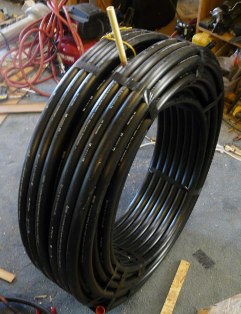
|
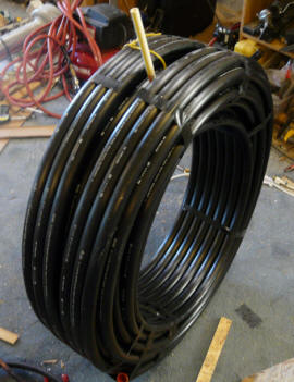
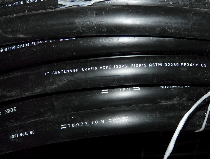
This is the 300 ft HDPE pipe coil.
For easiest installation, keep it in its
original coil shape.
Keep the end plugs in until you
are ready to make the final connections |
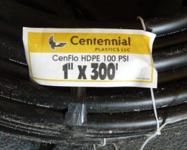
Label on pipe |
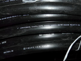
Label on the pipe. Note the NSF potable water stamp. |
The picture above shows the 300 ft
coil essentially as it comes. It is best to just leave it in this coil
shape rather than trying some kind of recoiling to fit your tank -- this can
lead to a real mess. In my case the full size coil would not quite fit
through the crawl space hatch, and in this picture I am dividing it into two
connected coils to pass each one through the hatch separately.
The pipe I bought is rated at 100
psi. I intentionally chose the lowest pressure rating just to see how it
did and whether any problems will result. You can get the HDPE all the way
up to 200 psi, and these higher pressure ratings will provide more margin of
safety.
Be sure that the pipe is NSF rated
for potable water -- do not get "utility" or irrigation grade pipe.
Heat Exchanger supports
The heat exchanger should be
supported up off the bottom of the tank to get it into the hotter part of the
tank when the tank is stratified.
I used 3 full size concrete blocks to
do this.
|
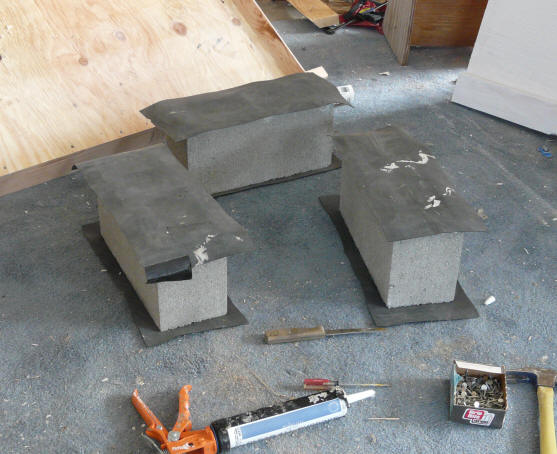
The concrete block heat exchanger
support. Scraps of EPDM are
silicone cemented to the top and
bottom of each block. |

The three heat exchanger support
blocks finished. |
To prevent an abrasion between the
blocks and the pipe coil or tan bottom, I siliconed scraps of EPDM on the top and
bottom of each block.
In general you need to be careful
about materials used inside the tank. The temperature is high and its wet
:)
Silicone, EPDM, polypropylene cord
all seem to be OK. Most kinds of metal fasteners don't do well --
including galvanized.
|
|

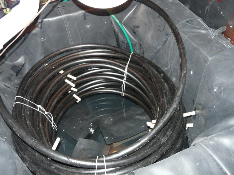
Pipe coil in the tank. |
The picture above shows the pipe coil
sitting in the tank and resting on the 3 support blocks. Short lengths of
half inch CPVC pipe are used to space the coils apart -- this allows for better
heat transfer from the storage tank water to the pipe coil. The coils are
tied into shape using the white propylene cord. The two ends of the
300 ft coil are unwound just enough to lead them over the top of the tank sides
-- they will pass through sealed openings that are above the EPDM tank liner.
When filling things up, fill the pipe
coil first, then the tank. If you don't do it this way, the pipe coil will
just float up on top the tank water.
Note that there are no penetrations of
the tank liner, and there are no plumbing fittings inside the tank. That
is, the ends of the HDPE pipe are taken outside the tank where the connections
to the house hot water plumbing are made.
Since the fluid in the tank is plain
old water, there should be no issue of needing a double wall heat exchanger, but
this is something you might want to confirm with your local code folks.
The two ends of the 300 ft pipe coil
must be brought out of the tank to connect into the cold water pipe going to the
existing hot water heater. To do this, I cut two slots in the edge
board that was just installed. Each slot is just wide enough for the 1 inch pipe
to exit through. I located these slots to allow the HDPE pipe to exit the
tank in a straight line tangent to the pipe coil circle. This
allows you to have the pipes exit without kinking or bending them.
The pipe is about 1.25 inches outer diameter, and the edge board is a bit less
than an inch thick, so the pipe will stick up a bit above the edge board -- this
is OK -- the EPDM lining on the lid will accommodate these small bumps.
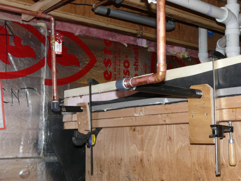
Picture shows the two ends of the 300
ft HDPE coil exiting from the tank. The light gray board is the tank edge
board, and the pipe exits the tank through slots cut in this board. The
small plywood board that the HDPE pipe goes through at the edge of the tank
holds the HDPE in place.
The 1 inch HDPE is adapted to the 3/4
inch copper pipe with a standard 1 inch barbed to 3/4 inch threaded, right angle
adaptor. At the time this picture was taken, clamps were still being
used to hold the lid down.
The Lid
The lid is important. It must
seal down to the tank well, otherwise it will leak a lot of water vapor out,
which is a big heat loss and also not good for your crawl space or basement.
The lid also provides the insulation to prevent conductive heat loss out the top
of the tank.
My lid (from bottom to top) is a
layer of EPDM, a 2 inch layer of rigid polyiso insulation, a layer of hardboard
(could be half inch plywood). The lid is large enough to go to the
outer edge of the edge boards you installed earlier.
Cut out the plywood tank top large
enough to cover the edge boards on top of the tank. Then cut the rigid
foam board insulation to the same size.
Glue the foam board insulation to the
plywood lid using the polyurethane foam in a can. Use some weights on the
plywood to keep the foam from expanding until it sets.
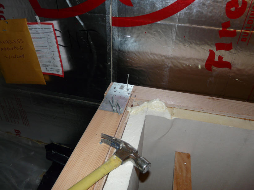
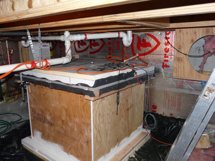
On my tank, the plumbing connections
between the tank and the collector go through the lid. The part of
the lid that these connections go through is permanently sealed to the tank.
In my case, I used a triangular shaped piece at the corner of the tank closest
to the collector for this fixed portion. Your plumbing arrangement
will dictate which portion of the lid you want to make fixed to bring your
collector plumbing in.
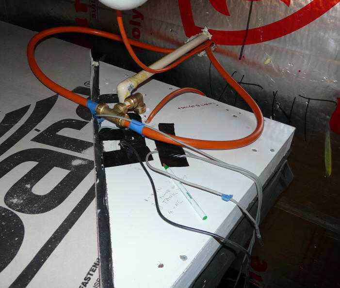
This shows the part of the lid that is fixed in place (white triangle).
Having a fixed part of the lid allows the main part of the lid to be removed
without disturbing the plumbing connections.
The orange PEX-AL-PEX lines connect to the bottom of the collector (one to
left side and on to right side). They are
T'ed together, and
the single line then drops down through the tank lid and connects to the pump.
The electrical wire for the submerged pump goes down through the tank lid right
next to the PEX.
The white CPVC line comes from the top of the collector. This line
penetrates the lid, and ends
above the waterline in the tank. When the drainback process starts, air
goes up this line to allow the
drain back to occur -- so the line must end above the tank waterline.
So, decide where the fixed portion of
the lid will be on your tank, and cut off that portion of the lid -- so, now you
have a lid in two parts -- one fixed and one that can be removed. I would
make the fixed part as small as practical. The electrical wire for the
pump power will also go through this part of the lid.
Cut a piece of EPDM that will cover
the removable part of the lid, and make it large enough so that it will wrap
around the edge of the insulation and up a little ways onto the plywood.
This will let you staple the EPDM to the plywood to hold it in place.
Lay the lid on the floor with the
insulation up, apply some bead of silicone, then lay the EPDM over the
insulation. Flip the lid over, and pull the EPDM up over the plywood and
staple it in place.
Do the same with the fixed part of
the lid.
Temporarily clamp the fixed part of
the lid over the tank, and work out exactly where your plumbing penetrations
will be. You will need one penetration for the collector supply line (from
the submersible pump), and a 2nd line returning water from the collector to the
tank.
You will also need a hole for the
pump electrical connection.
Drill these holes for a snug fit of
the plumbing lines.
The hole through the EPDM layer
should be just large enough to allow you to push the plumbing lines through the
EPDM -- this way the EPDM will seal around the lines.
Install the fixed portion of the lid
with long screws. Very long coated deck screws work well.
Use a light bead of silicone between the
edge board and the lid. The silicone does not adhere strongly to the EPDM,
so you will not have any trouble removing this portion of the lid later if need
be.
At this point, the large and
removable portion of the lid can be put in place and secured. Initially,
you may just want to use a clamp on each edge to keep the lid down. When
you are sure that everything in the tank is done, you can screw the full lid
down with long screws.
You can also add another layer of
insulation board on top the tank to further reduce heat loss.
| |
Warning: The
water in the tank will reach temperatures that will result in scalding
or death to kids or pets that get into the tank. Be sure that the
lid is always secured in such a way as to prevent this kind of incident.
|
|
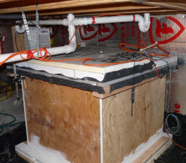
Tank with lid on. |
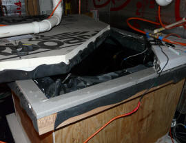
Lid partly open.
The lid seals against the grey edge board.
The seal must be good enough to prevent
water vapor from escaping. |
This is a picture of
the tank with lid on. The lid is the part above the light grey tank
edge board.
The lid layers from the bottom are:
1) EPDM
membrane,
2) 2 inches of
insulation,
3) half inch
plywood or OSB,
4) 2nd layer of insulation lightly secured to plywood.
The lid is still
being held down by clamps when this picture was taken.
Plumbing
Connections
Update
November 11, 2008: Details on the new pump ...
Collector Plumbing
A submersible pump is located near
the bottom of the solar storage tank. Water from the tank is pumped by
this pump up a line that goes through the lid of the tank. This line is
T'ed off into two lines -- one line feeds the bottom of the left half of the
collector, and the other line feeds the bottom of the right half of the
collector.
Water returning from the two halves
of the collector are joined into a single pipe at the collector, and this pipe
runs down to drain back into the airspace above the water in the storage tank.
When the pump turns off, all of the
water in the collector and collector plumbing drains back into the storage tank
-- this provides freeze protection. No antifreeze is used.
I have used a solar PV panel to
directly power a small submersible pump, and this also worked well. In
this case, a thermal snap switch should be installed in the power line to the
pump to shut if off when the tank temperature reaches 140F. The thermal
snap switch could probably be installed between the EPDM lining and the first
layer of insulation, and near the top of the tank.
With either type of pump, when the
pump starts up, it must have sufficient pumping head capability to pump water
from the water level in the tank up to the top of the collector. So, if
the top of the collector is 8 vertical feet above the level of the water in the
storage tank, the pump must have a startup head rating of at least 8 ft.
Once flow is established, and all the pipes are filled, the required pumping
head drops down to just the friction losses in the system.
The pump should be able to produce a
flow through the collectors of around 0.04 to 0.05 gpm per sqft of collector
area. So, for my 48 sqft collector, about 2 gpm is sufficient.
|
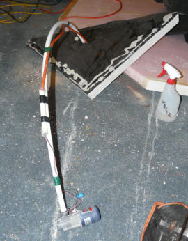
This is the small March pump that
is submerged in near the bottom of
the tank to pump water to
the collectors. |
Wiring the pump with a waterproof
connection. |

Close-up of the pump. |
The picture shows the March pump I am
currently using to pump water from the tank to the collectors. It is a
March 893 12 VDC pump.
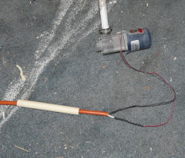
The pump is very light weight, and
simply hangs from the PEX outlet line. The wire supplying the pump had to
be spiced below the water level in the tank. To do this I soldered the
wires together, than used heat shrink tubing, and finally I put a length of half
in CPVC over the connection and filled it with silicone.
Since the controller provides a
120VAC outlet for the pump, I have a small 12 VDC power supply I plug into the
controller -- the pump is then powered by the 12 VDC power supply. The
power supply and pump together only draw 20 watts as measured with a
Kill-A-Watt.
I'm still looking for the ideal pump
and controller for this system. It seems like with the modest pumping
requirement and modest temperature requirement, there should be a high quality
low cost solution out there somewhere? Let me know if you have seen
something that might work better.
Update
November 11, 2008: Details on the new pump ...
If you are using one of the Grundfos
or Taco HVAC circulation pumps, please note
these installation cautions...
House Hot Water Plumbing
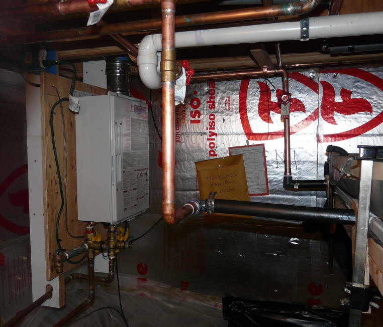
Picture shows plumbing connections
between solar tank and the house water heater.
The tankless water heater that
provides backup water heating when the solar heated water is not up to the
needed temperature. The tank is on the right.
Basically, the cold water inlet to
the tankless heater is brought over to the solar tank, and then back to the
tankless heater. This way if the water in the solar tank is already hot
enough, the tankless heater does not turn on at all.
I included valves that allow the
solar tank to be cut out of the system, and the cold water routed directly to
the tankless heater -- this way the solar tank can be worked on or drained
without turning off the home water.
OK, its not pretty, but its very functional and durable --- who needs pretty in
the crawl space?
Controls
A Steca differential controller is
used to control the collector pump. The controller uses a temperature
sensor mounted in the collector and a temperature sensor mounted in the tank
near the bottom. When the collector temperature goes above the tank
temperature by an amount that you can set, the controller turns the pump on and
circulates water through the collector to heat the tank. When the
collector temperature drops below the tank temperature, the controller turns the
pump off.
This controller also has a tank
overheat feature that allows you to limit the maximum temperature of the tank
water to a value that you set. I use this feature to limit the storage
tank temperature to 140F -- this insures a long an happy life for the EPDM
liner, HDPE pipe coil, and the pump -- its an important feature.
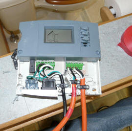
|

The Steca differential controller on top
controls the collector pump operation.
Its display shows storage temperature,
collector temperature, and when the
pump is operating.
The lower unit is the remote control
for the Tagaki tankless water heater.
It will display inlet and outlet temperature,
as well as flow rate. |
Wiring the Steca differential controller.
The two orange wires go to the
temperature sensors -- this is all
you have to hook up.
The wiring for these can be two conductor
18 gage, but I did not have anything
that light around, and used
heavier wire.
|
The wiring is very simple.
Install the temperature sensor in
the collector.
Install the temperature sensor in
the tank (look for one that can just be immersed right in the water).
Hook the two temperature sensors
up to the differential controller.
Plug the pump into the controller
(it probably has a 120VAC outlet for this).
Plug the controller into a wall
outlet.
That's all there is to it.
| |
A Problem with the Steca Controller
I have replaced the Steca controller with another brand after having
two failures.
The failure is that the controller will run the pump all the time.
Even when the display indicates that the pump is turned off, the
controller continues to run the pump. I've tried all the usual
remedies as in checking switch positions, cycling power, ... to no
avail. I believe that the relay that turns the pump on has
stuck on.
The first unit was replaced under warrantee, and the replacement
worked for about another month or two and failed in exactly the same
way. While they likely would have been willing to replace the unit
again, I decided that I would just change to another brand.
This seems particularly strange in that the pump only draws 13 watts
-- you would think that it would be very easy on the controller output
circuit?
I've written a note to Steca, and they believe that the problem is
that the DC pump is powered by a switching power supply. Its the
switching power supply that is plugged into the Steca, with the pump
then plugged into the switching power supply. The switching power
supplies can apparently have very high startup current surges, and they
believe that this is what caused the relay to stick with the contact
closed. I am inclined to believe this explanation.
One potential cure for this if you want to use the same type of DC
pump I use is to power it with a "linear" power supply. These
power supplies (I'm told) do not have nearly as high a startup power
surge, and should work OK. These linear supplies are widely
available and not expensive -- Digikey and Jameco are two places that
handle them.

The new controller is a Caleffi. It is actually quite similar
to the Steca with the added benefit that it displays cumulative pump
hours. Its a bit more expensive. So far (2 months) it has
worked well.
It hooks up in the same way as the Steca, and uses the same kind of
temperature sensors.
I got mine here:
http://www.houseneeds.com/Shop/solar/caleffi_isolar_main.asp
After hearing the Steca explanation, I am inclined to believe that
the Caleffi controller may also be susceptible to power startup surges
from the switching power supply, and if I were going to run the DC pump
in the long term, I would change to a linear supply, but see the update
just below.
Gary October 10, 2009
Update: April 23, 2010 -- I have changed the pump to a Grundfos AC
pump as a part of expanding the system to do both water heating and
space heating. This change does not in any way indicate a problem
with the SwiftTech pump, which performed without a hitch for more than a
year. I just needed somewhat more flow and startup head than the
SwiftTech is rated for with the new larger and taller collector. |
If a PV panel is used to run the pump, then the PV panel itself acts as the
controller. When there is sun on it, it pumps, and if not it does not
pump. It may be hard to find a pump that has enough startup head and can
be run from a modest size PV panel. But, the March pump I am using now
works ok with a PV panel. In order to keep the storage temperature
from going over 140F, a thermal snap switch can be installed in series with the
pump and mounted just under the tank liner. The snap switch wants to to to
open when it reaches 140F, and be closed at below 140F. One caution on
using PV to drive a drain back system is that the PV must spin the pump fast
enough on startup or after some clouds go by to pump the water all the way up to
the top of the collector. This did not seem to be a problem whit the March
pump I am using and a PV panel that is about 15 watts, but I'm not sure this is
always going to be true -- particularly if you collector is well above the tank.
Gary September 21, 2008, October 10,
2009, April 23, 2010