
Search
The Renewable Energy site for Do-It-Yourselfers
Radiant Floor Heat
Spreaders
|
I am putting in a radiant floor to
distribute the heat from the
solar collectors
I recently added.
The floor is going to be the type
where you remove the current finish floor, and add runs of PEX pipe on top of
the existing subfloor with with plywood spacers between the PEX runs to make a
surface level with the top of the PEX tubing. You then place place your
finished floor over the spacers. Solar heated water is then circulated in
the PEX tubing to heat the floor.
To make this work efficiently with
solar heat, it is desirable to be able to use as low temperature water as
possible for heating. This makes it desirable to have low thermal
resistance in the finished floor, and to have an efficient means to spread
the heat from the tubes to the finished floor efficiently.
|
|
Aluminum heat spreader plates are
often used to spread the heat more efficiently on radiant floors. There
are some commercial ones of various types, but, being cheap, I am building my
own using sheet aluminum.
There is also an issue of how to
install the spreader plates. They typically consist of a flat plate
with a groove or trough formed down the centerline that the PEX tubing fits in.
You have two choices on how to install this: 1) with the groove facing up, in
which case the spreader plate lives right on top of the plywood spacers (just
under the finish floor), and 2) with the groove down, in which case the spreader
plate is sandwiched between the plywood spacers and the existing subfloor.
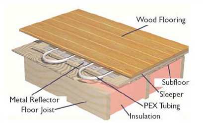
Shows the sandwich style radiant
floor with alum heat spreaders. This is version 1. With version 2,
the alum spreader plate would be between the "sleeper" and "subfloor".
Having heard arguments for both
methods, I did a little test to try to figure out which worked best. I
took a 6 ft length of PEX tubing, and used the first 2 ft with the grooves up,
the 3rd 2 ft 2 ft with the grooves down, and the middle 2 ft with just the
plywood spacers (for a baseline to compare with).
I ran hot water through the PEX, and
measured the temperatures in each of the three segements at a three points: 1)
over the centerline of the PEX, 2) 1.5 inches to the side of the PEX, and 3) 3
inches to the side of the PEX. In all cases, the PEX and spacers were
covered with a thin foam underlayment and an 8mm laminate floor.
The "subfloor" is supported by 2X4's
on each edge, and is insulated underneath to roughly simulate a real floor.
The spacers that the PEX is placed
between and the subfloor are 3/4 plywood. The alum heat spreader is 0.019
sheet alum (alum soffit material). A groove is formed in the alum that
fits the PEX tube OD fairly snugly, and a bead of silicone is laid down in the
groove before the PEX is put in it to improve heat transfer. The tubing is
generic half in PEX (I plan to use PEX-AL-PEX on the actual floor).
The graph shows the temperature
profiles for each spreader plate:
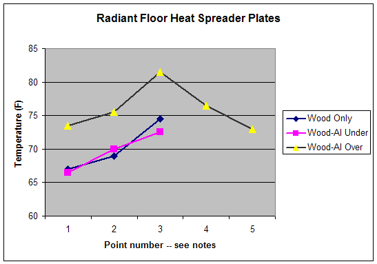
Point 3 is on the top of the finished
floor, and directly over the PEX tube.
Point 2 is on the top of the finished
floor, and 1.5 inches from the PEX tube.
Point 1 is on the top of the finished
floor, and 3.0 inches from the PEX tube.
Tambient = 69F, Twater = 92F
The drop in water temp from inlet to
outlet was about 0.5F or less -- so all three segments get nearly the same
temperature water.
All temperatures measured with and IR
surface thermometer.
I was surprised how much difference
there was between the two arrangements (groove up and groove down), which I had
been lead to believe would be very similar.
It looks to me like the alum spreader
plate just under the finished floor, and over the plywood spacers is
substantially better in getting heat to the room. That is, for the same
water temperature, it is producing finished floor surface temperatures that are
6 to 7F better -- a near 100% improvement in the temperature drop from tube to
finished floor.
For solar heating, where it is
desirable to use low temperature water, this seems like a very worthwhile gain.
I'd like to hear if there are disadvantages to this way of putting the
spreader plates in that I don't see??
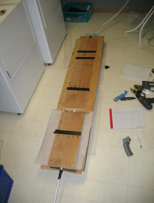
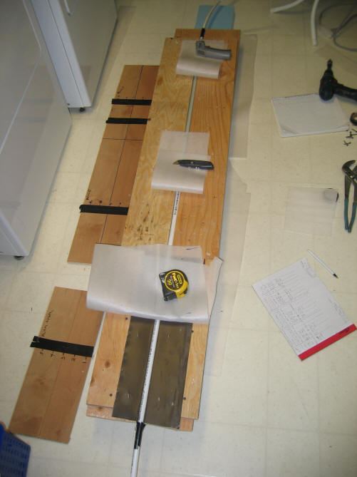
The test setup. Stackup is: 1)
laminate floor, 2) thin foam underlayment, 3) PEX tube between spacers or
sleepers, 4) 3/4 plywood subfloor, 5) 2X4's supports on edges. The
temperatures were measured using an IR thermometer on the black tape strips at
the numbered points.
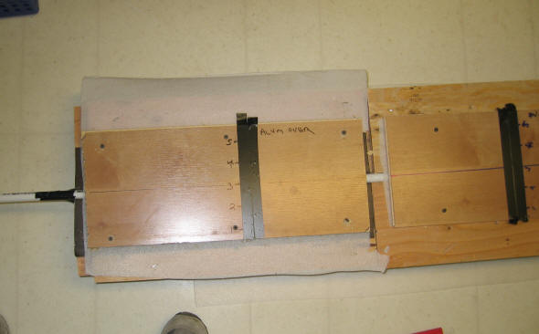
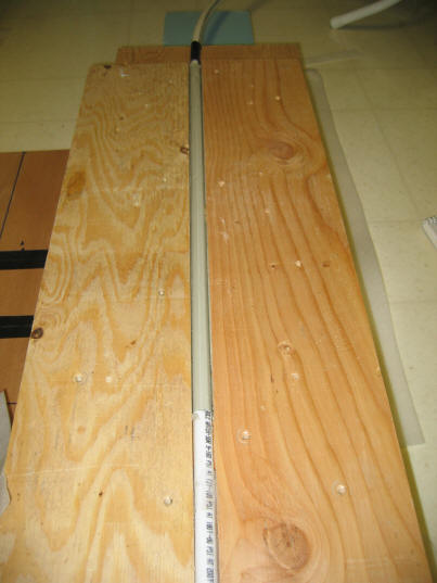
Detail of the first two feet with the
heat spreader right under the foam underlayment. The bit of brown visible
to the right and left of the laminate is the top of the alum heat spreader.
Shows the setup with the finish floor
removed, and the foam underlayment folded back.
The closest segment is the "high
performing" alum just under the finished floor. The next one is wood with
no alum spreader, and the top one has the alum spreader sandwiched between the
subfloor and spacers -- the grey you see is the groove going over the PEX tube.
Detail of start transition from no
spreader plate to spreader plate under spacers.
Gary 11/14/06