Using Smoke For Flow Visualization in Solar Collectors
After trying a number of approaches to using smoke for visualizing the airflow for solar air heating collectors, I've found a method that works pretty well, and thought I would pass it on.
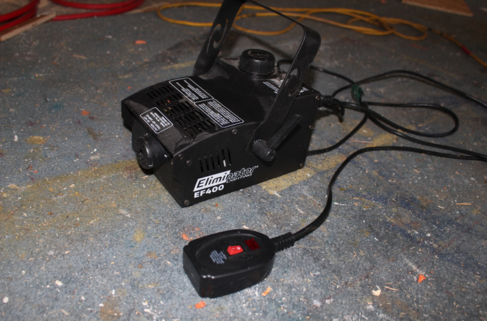
This method uses a small theatrical fog generator to make the smoke.
It can be used both to generate quite a bit of fog to see the flow over the whole absorber, or for spot applications to see the flow for just a small part of the collector.
Mode 1: Flow at a point
In this mode the idea is to see what is where the flow is going for a small area. The end of a tube is placed at the point being examined, and smoke is pumped through the tube so that it comes out at the point of interest.
After a warm up period, this fog machine pumps out smoke through the opening on the front. The smoke is made from "fog juice" which is (I think) polypropylene glycol. The smoke is actually not a combustion product, but is very small condensed droplets formed from the vapor of the fog juice. The button on a cord allows you turn the smoke on by pushing the button -- short burst if you just press and release the button, or hold the button down for continuous fog.
The machine takes a minute or so to warm up, and then it will produce fog for 30 seconds or so before it has to stop and warm up again. This is not really a problem as one batch of fog is enough for quite a bit of flow visualization.
So, the fog coming out of the machine has to be directed into the tube your are using for flow visualization., and you have to have some way to control the timing and volume of smoke coming out of the tube. I tried a couple ways that did not work before coming up with the method described below that works pretty well. Ideas for better ways would be great.
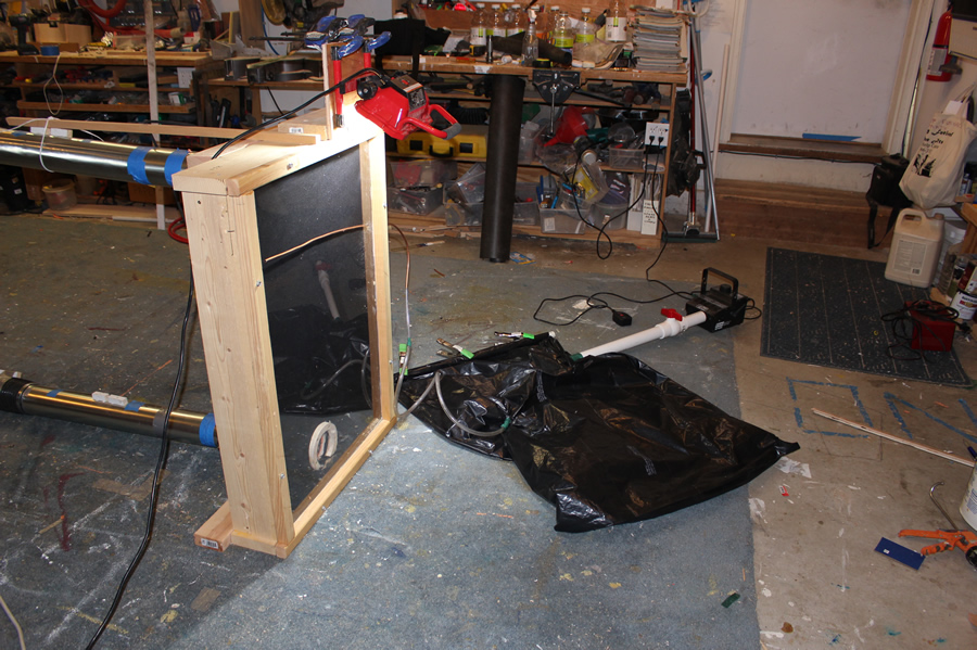
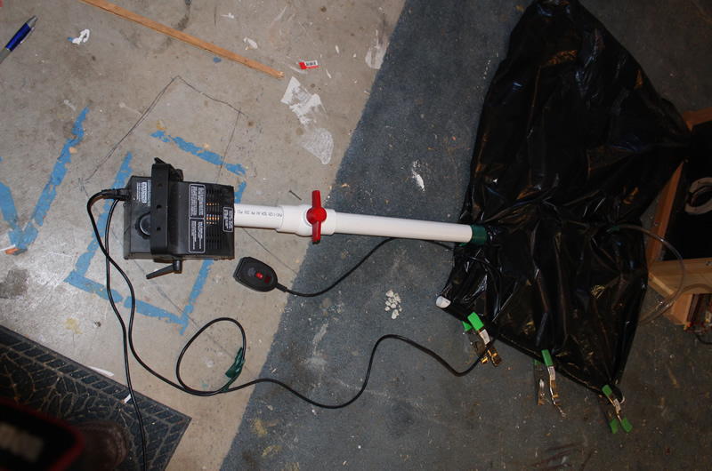
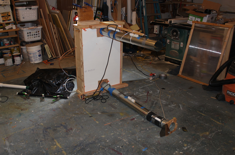
I ended up using the smoke machine to fill up a large (50 gallon) heavy duty garbage bag. A large tube goes from the fog machine to the bag to fill it up, and the flow visualization. tube goes from the bag to the collector to place smoke where you want it. The timing and volume is controlled by just putting some pressure on the bag with a hand.
This shows the whole setup before smoke was blown into the bag.
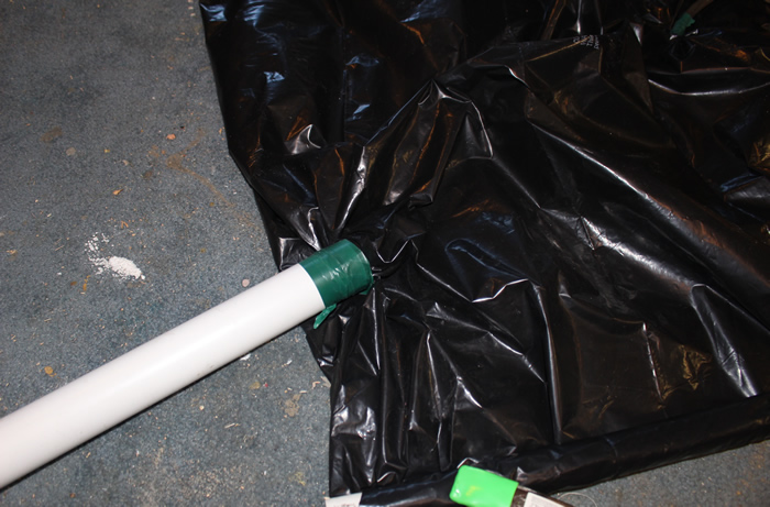
The large tube from the fog machine to the bag is just pushed through a small hole cut in the side of the bag and then tapped over with electrical tape.
This 1.5 inch PVC pipe fits the outlet on the smoke machine with a good friction fit.
This shows the 1.5 inch PVC tube going from the fog machine outlet to the bag. The valve is open when blowing smoke into the bag, and closed after its filled -- it keeps smoke from being pushed back through the fog machine when you are putting pressure on the bag.
None of these fittings needs to be solvent welded -- just a friction fit is fine.
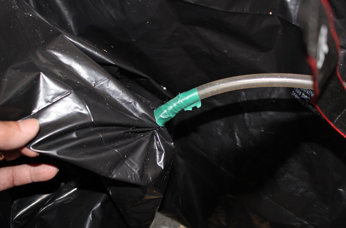
The small tube used to convey the flow visualization. fog is inserted into the bag via a small hole made with a knife and then tapped over.
These tape connections are holding up fine.
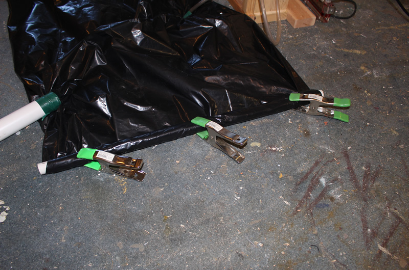
The end of the bag is sealed off by rolling it up on some 3/4 inch PVC pipe and clamping it.
Showing the end of the bag sealed off by rolling it up around the PVC pipe and then clamping it.
Filling the bag with smoke. As soon as the bag is filled, turn the valve to the closed position to keep the smoke from flowing back to the fog machine.
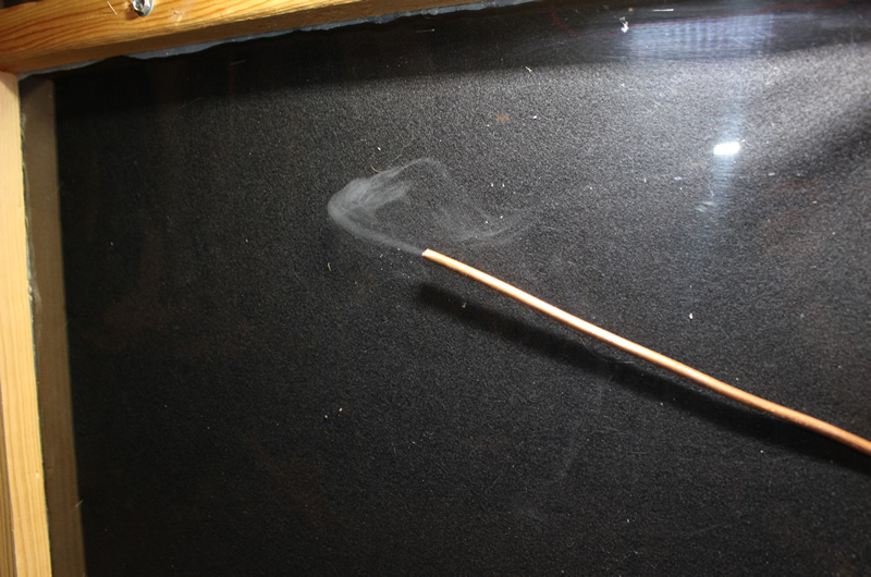
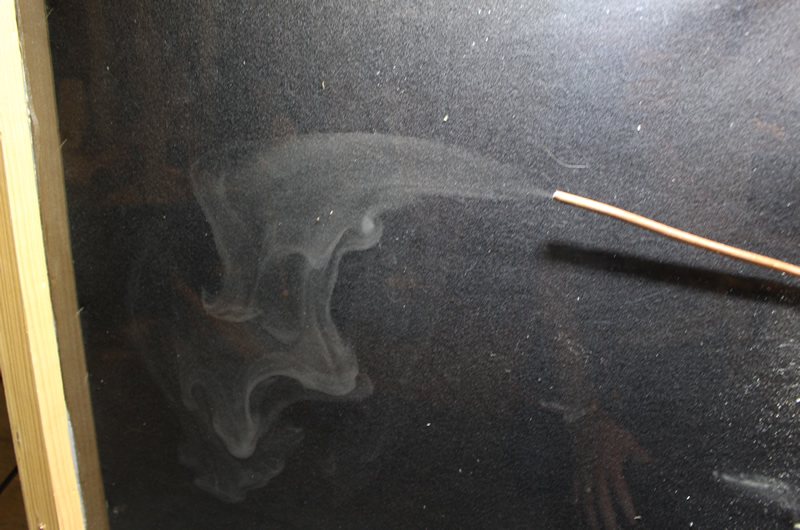
The whole setup before the bag has been filled with fog. The copper tube goes through a hole in the side of the collector and can be positioned anywhere in the space between the absorber and the glazing. It could also be positioned behind the absorber to see if there is any backflow from the back side of the absorber to the front side.
The red LED shop light clamped to the top of the collector side lights the smoke and makes it more visible.
Smoke coming from the end of the visualization. tube. By varying how much you push the side of the bag the rate can be easily controlled. When you stop pushing on the side of the bag the smoke stops.
Another picture of the fog -- I believe that this one was without flow through the collector.
This particular collector absorber had lots of layers (2 screen + 2 weed fabric + 2 felt), so the flow is less energetic than it would be for something like a 2 screen absorber.
After trying several other methods that did not work very well at all, I was quite happy with this and think that it will be helpful trying to work out just where the flow actually goes on various parts of the absorber.
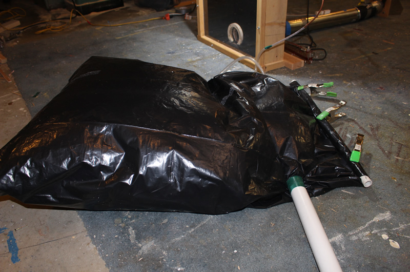
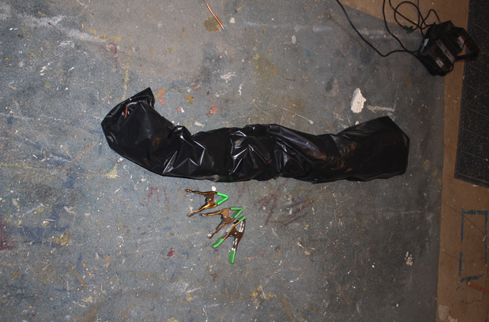
When not in use, the whole setup rolls up into a compact package.
Mode 2: Overall flow through he collector
In this mode, the fog machine is just hooked up to the collector inlet (the fan inlet in my case), and when the fog button is pressed, a pretty good volume of fog blows into the collector and you can watch where it goes through the glazing.
I did not get a picture with the fog machine set up to blow into the fan inlet, but you jus position the fog machine with its outlet right in the fan inlet. The fan inlet here is on the near end of the lower duct.
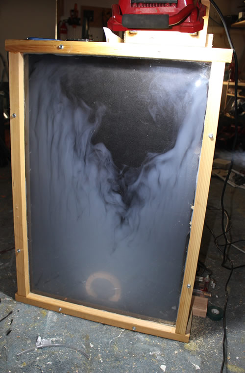
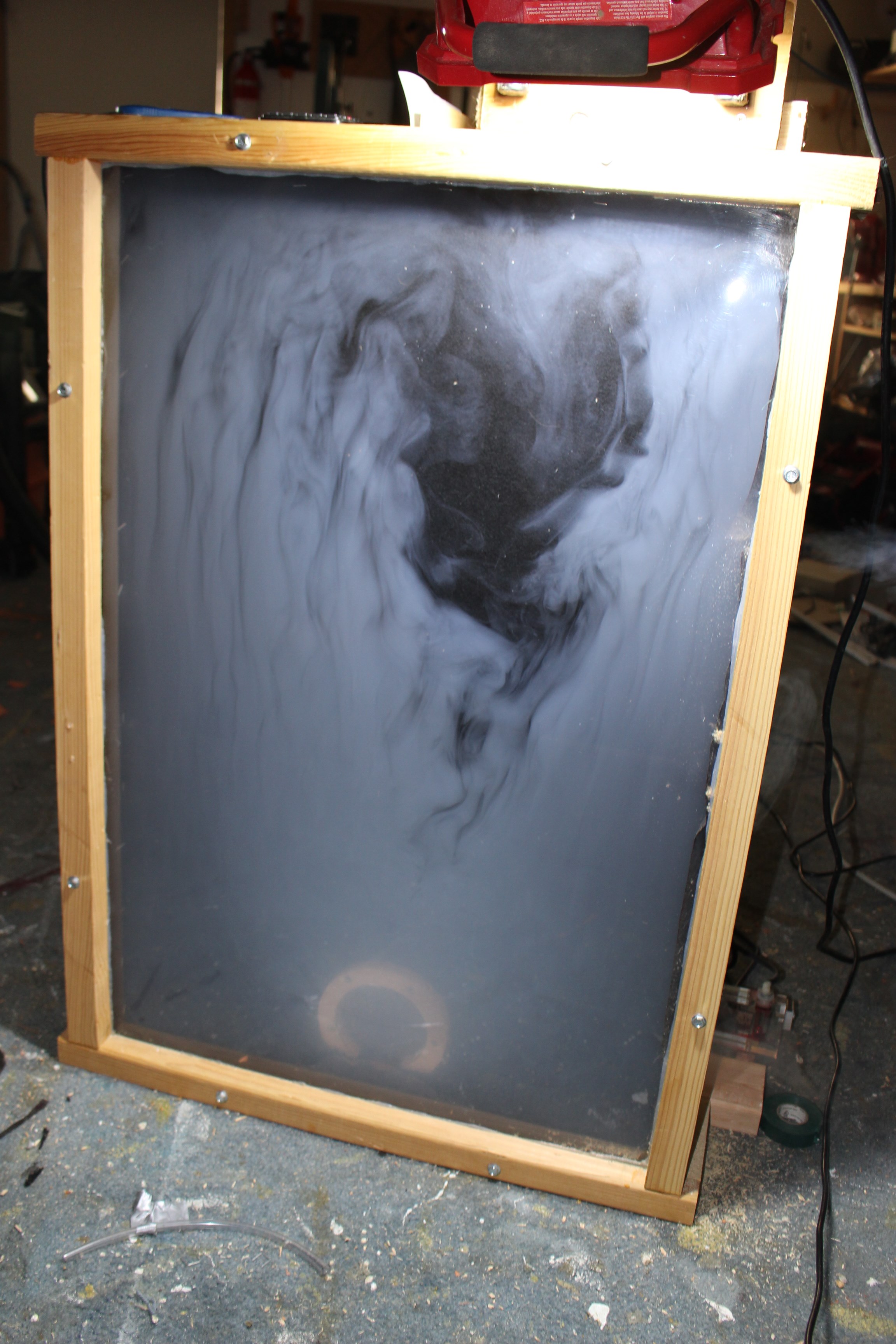
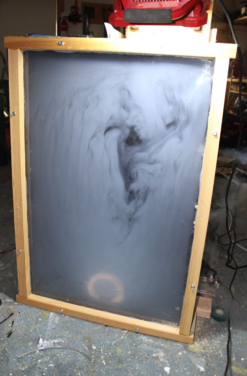
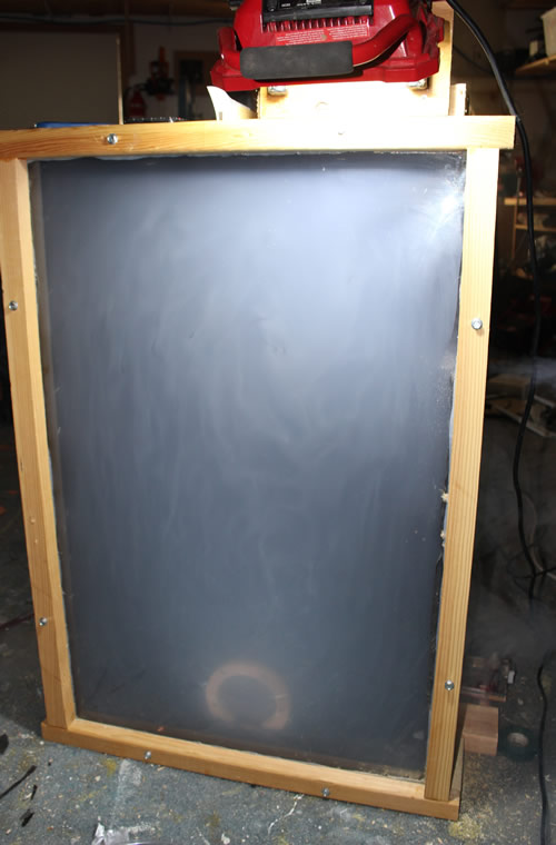
This is a sequence of pictures taken as a burst of fog comes into the collector and makes its way up and out:
The flow tends to shoot up the sides faster than up the middle -- the opposite of what I would have guessed.
I was a little late getting the first picture -- the flow up the sides is even more dominante earlier.