
Search
The Renewable Energy site for Do-It-Yourselfers
Try a Collector
Made From EPDM Rubber Sheeting
|
was going to make the
collectors for the Solar Shed by buying
conventional, pre-made absorbers (copper tube risers with copper fins), but
after reading David Mears description of the the very simple collectors they
made for heating greenhouses, I got to wondering if I could do a collector that
has most of the simplicity and cheapness of the Mears collectors, but with
better durability and a longer life.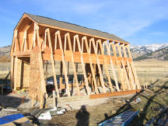
The collector would
go
on the open
face
of this storage
shed, with
hot water piped to
the house for space
heating.
|
|
I
The design I am thinking about has
two sheets of EPDM rubber that form the absorber. The water to collect
heat from the absorber would flow between the two sheets. The water would
be fed in at the top via a manifold, and collected at the bottom via a pipe or
gutter. The collector would be glazed with twinwall polycarbonate glazing
panels. The potential advantages of this are that 1) the materials would
cost less than half as much as the conventional collector absorber, 2) it would
be simple to make, 3) its pretty forgiving for freezing (it might survive a
failure of the draindown system), and 4) it seems to me it should have just
about the same efficiency as a regular flat plate collector(?).
It seemed like the most challenging
thing in this design is to get the water to flow uniformly between the two
sheets of EPDM, and to fully wet the back side of the front sheet. The
front side (south side) of the front sheet receives all of the solar input.
The water flow along the back of the front sheet must remove the solar heat
uniformly over the full sheet. If it does not, parts of the EPDM sheet
will overheat, which will lead to a shorter life and higher loses.
I set up a little test fixture to try
to see if I could get the desired uniform water flow over the full EPDM sheet.
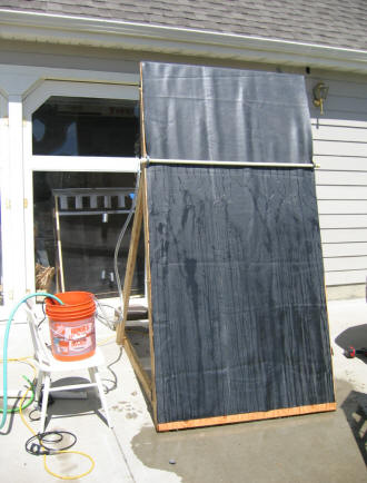
The plywood and 2X4's support the
sheet of EPDM at the same 70 degree angle they will be in on the solar shed.
The water is pumped out of the orange bucket by a small submersible pump in the
bucket at 1 gpm. The water is distributed to the EPDM sheet by the white
plastic pipe, which has 1/16th holes drilled on 2 inch intervals. Normally
the manifold would be at the top of the sheet, but I lowered it for the test
just to make it easier to reach.
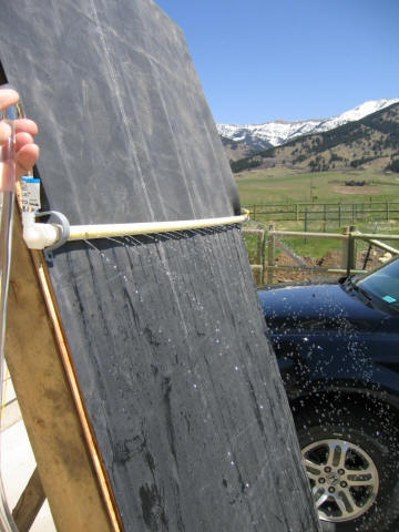
This picture shows jets of water
coming out manifold -- 1 gpm total over the 4 ft width. One gpm per 4 ft
is about what the flow will be on the real collector in order to remove the heat
with a no more than 10F temperature rise.
I did this first series of tests with
just one sheet of EPDM so that I could see how uniform the flow is.
Try 1: Just let the water flow
down the EPDM sheet and see how uniform it is:
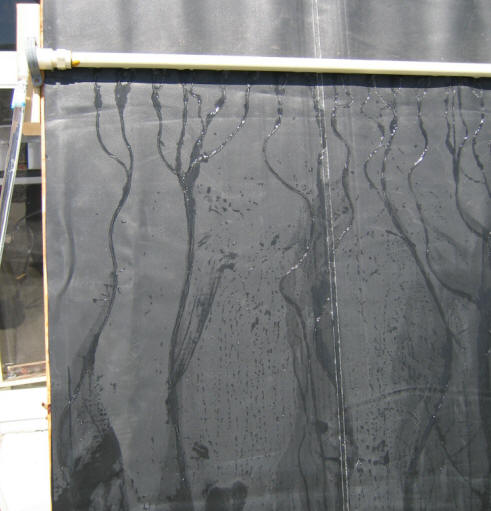
The water does not spread out
uniformly, but stays in little streams that wander around, and sometimes join up
to form a larger stream. After a minute or so, a stable pattern emerges,
and only a small percentage of the sheet area is wetted. Surface
temperatures are around 40F near the streams, and up to 90F between streams.
So, this does not work very well.
(all these temps are too low, as
something seems to fool the IR temp meter, but the differences are probably
pretty close).
Try 2: Add Detergent
I tried washing (scrubbing) the EPDM
surface with a water/detergent solution, and tried adding detergent to the water
in the bucket.
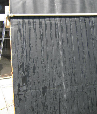
This is with detergent in the water.
It straightens out the flow streams, but does not spread the water out into a
uniform film.
Try 3: Add a sheet over the back
sheet
I added a sheet of clear Vinyl over
the EPDM sheet to see if the flow would spread out between the two sheets.
Hopefully, the Vinyl acts pretty much
like the front sheet of EPDM would act, but allows you to see the flow(?).
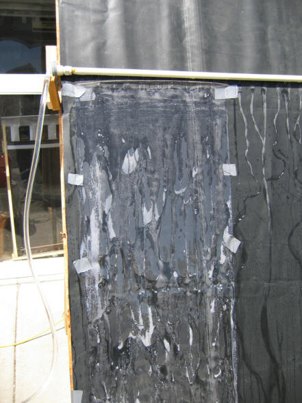
This is the clear Vinyl shortly after
it was put on. There is no detergent in the water.
Its a little hard to see in the
picture, but, while the Vinyl spreads the flow a little, it is still highly
channelized.
The light areas are small air bubbles
that start to form under the Vinyl almost immediately.
The area at the top of the sheet has
more uniform flow because I ran my hand over it.
Try 4: Squeegee the Vinyl sheet
I ran a block of wood over the full
surface of the Vinyl sheet to force it into contact with the back EPDM sheet.
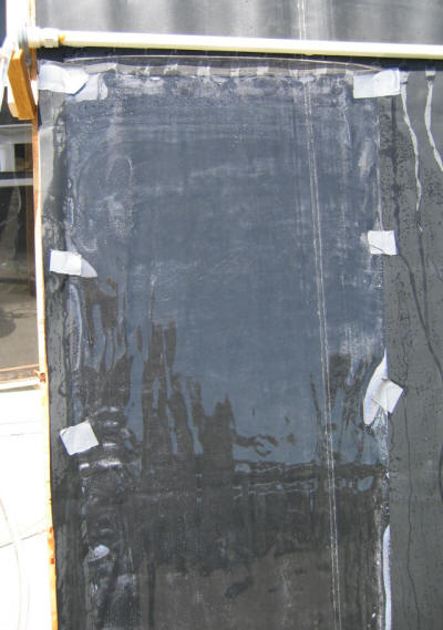
As you can see from the picture, this
makes for much more uniform flow. There is still some temperature
variation where the Vinyl pulls away just a bit from the EPDM. but much better.
The temperature variation is about
10F from the coldest to hottest spots.
This is taken right after the
squeegee.
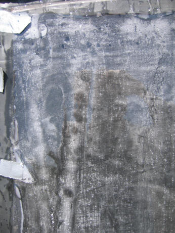
Within a short time, the white areas
on the picture to the right start forming. These are small bubbles.
Not sure that these have any bad
effects, but it does not seem like a good thing?
So, this has a bit of promise, but
the fact that it takes the squeegee to get the uniform flow started is a
problem. It would be a pain to have to go out and squeegee your collector
on each startup :-)
Try 5: Add a Shade Cloth Layer Over
the EPDM
This is what Mears used to even out
the flow over his PE plastic absorber.
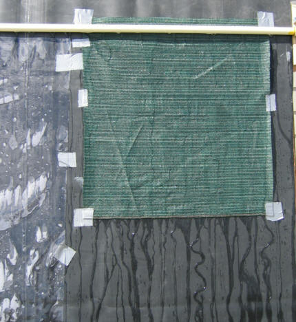 Its
a bit difficult to see in the picture, but this does have a somewhat beneficial
effect.
You can see in the picture that the
flow off out the bottom of the shade cloth is more uniform.
Its a bit hard to see, but there is
still some channeling, and, while the temps are fairly uniform, there is still
some variation.
The channeling tended to get a bit
worse as time went on.
I tried putting the layer of Vinyl
over the shade cloth, and it worked poorly.
It seems without something to push
the Vinyl against the shade cloth, the flow on the back of the Vinyl sheet is
only in contact with a small part of the shade cloths (and water).
The Mears collector is basically like
a two skin greenhouse with a very low air pressure between the two skins.
This air pressure tends to compress the absorber layer, shade cloth layer, and
top skin together -- this may make for more uniform flow.
Try 6: Try a Finer Weave Material
Instead of Shade Cloth
I thought that the coarse weave of the shade cloth might be responsible for
the non-uniform flow, so I tried a piece of weed fabric that is more pliable and
has a finer weave. Its a bit hard to see the cloth, since its the same
color as the EPDM, but if you look closely, you can see the bottom edge.
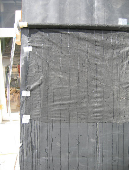
This worked poorly. The streams from the manifold just went straight
down the fabric with no spreading.
It gets somewhat better if you squeegee it out.
So, this is not working so well yet.
None of the tries results in a
uniform flow of water over the full surface of the EPDM being established
automatically.
It seems even less likely that when
the top sheet of EPDM (which is the actual absorber) is added that the flow of
water will be in uniform contact with it.
Thoughts:
The idea of using two sheets of EPDM
is that the heat transfer water is kept between them, and the cavity between the
top EPDM sheet and the glazing is dry.
If you went with one EPDM sheet with
water flowing on the sun side, then the glazing would be exposed to hot moist
air, and condensation on the glazing would reduce efficiency. The
polycarbonate glazing may not hold up to these conditions.
An alternate would be to have a film
type of glazing over the EPDM to separate the water from the PC glazing.
This would still require a way to
make water flow uniformly over the EPDM (maybe doable), and would also require a
film glazing that would hold up well.
A somewhat similar setup would be to
go with corrugated metal siding similar to the Thomason collector, but with the
film glazing.
About 9/06
3/29/07 note -- getting the water to
spread out more evenly would be easier with a lower tilt angle.
--------
Summer 2007:
Did a little more work on this with
other materials over the EPDM to spread the water.
Placing an ordinary cotton bath towel
over the EPDM works nearly perfectly.
Bed sheet material also works pretty
well -- not as good as the towel, but good.
So, perhaps fabrics that take water
into their fibers work best?
Gary Dec 6, 2007
