A Sun Simulator for Solar Thermal
Collector Testing
I've been doing some solar thermal collector testing (here
and
here) and plan to do
more. The method I've used is to test a baseline collector
side by side with the new design at the same time under the same sun.
This works well, but it has the disadvantages that you have to wait for
good steady sun, and you have to run the test and collect all the data
for both collectors, which is time consuming.
I've decided to have a go at building an indoor sun simulator that
will allow me to do indoor tests of moderate size collectors. If
it works, this has the advantages of being able to test under the same
sun conditions anytime without waiting for the right conditions, and
without the need to always do side by side tests with a reference
collector.
I've run into some difficulties with the
reflector design on the sun simulator and would appreciate any
help or ideas you might have.
The stuff below goes through what I've done in getting to a sun
simulator design, and the initial test of the design -- then into the
problem I'm having with the reflector design.
I should say first that indoor sun simulators are nothing new, and there are
are many commercial and collector research sun simulators out there. The problem with the
commercial ones is that my budget is hundreds of dollars, and the commercial sun sim prices are more like tens of thousands of dollars and up. So, the
question is, can a person put together a useful sun simulator on a low budget.
My goals are to:
Be able to test collectors up to about 2 ft by 4ft
Produce simulated sun light levels up to full sun (1000 watt/sm)
Produce a light pattern that is even enough to not throw off test
results
Be able to reproduce the same test conditions (light levels and
patterns) on each test.
Be able to test at part sun levels as well as full sun
Have a way to calibrate the indoor sun simulator to equivalent actual
(outdoor) sun levels
Not spend more than a few hundred dollars.
My first thought was to use halogen lamps. I thought about the
inexpensive halogen shop lamps and the halogen PAR spot lamps and did a little
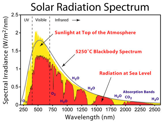
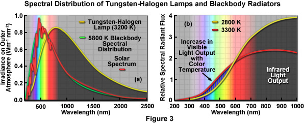
experimenting with each. The problem with the halogen lamps is that their
color temperature is low compared to the sun (about 2900K vs 5500K) and they put
out LOTS of their energy in the IR. So, while it looked like it was possible to use halogen
lights (and some commercial sun sims do), it seems like the halogen spectrum
being so heavily weighted to the IR would make testing results doubtful.
Looking around at the various existing sun simulators, and the data on
various lamp types, it looked like metal halide lamps offer the best
overall properties --
Higher color temperature (4200K typical) and less energy in the IR -- a closer
match to the solar spectrum.
Good efficiency -- about 90 lumens per watt -- so less power and less
waste heat to get to the light levels needed
Lots of light output from a single small lamp -- lamps up to 1000 watts
are widely available (it would take about 30 T8 fluorescents to equal one
metal halide)
Fairly inexpensive -- a 400 watt, 36,000 lumen metal halide lamp
plus the ballast to run it can be bought new for about $50
Metal halides are widely used in street lighting, warehouse lighting,
plant growing, .... so, they are widely available in lots of sizes and
flavors.
If they don't work, I can always take up growing Pot and use them for
that :)
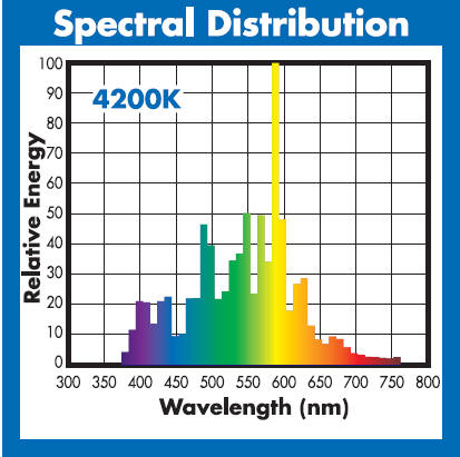
Metal halide lamp spectrum for the lamps I'm using.
The spectrum of the metal halide lamps can be varied by using different mixes
of metals in the arc tube. The most common ones have a color temperature
of about 4200K.
Initial Setup
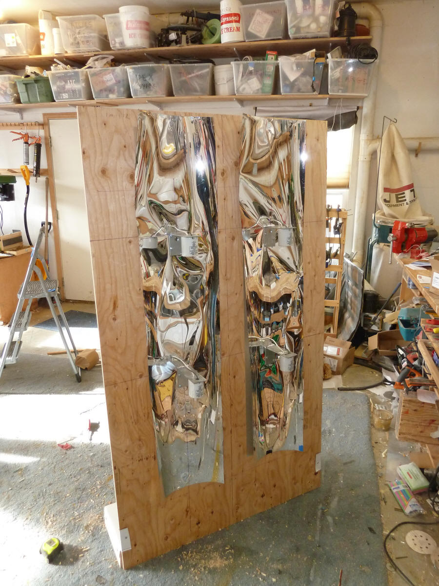
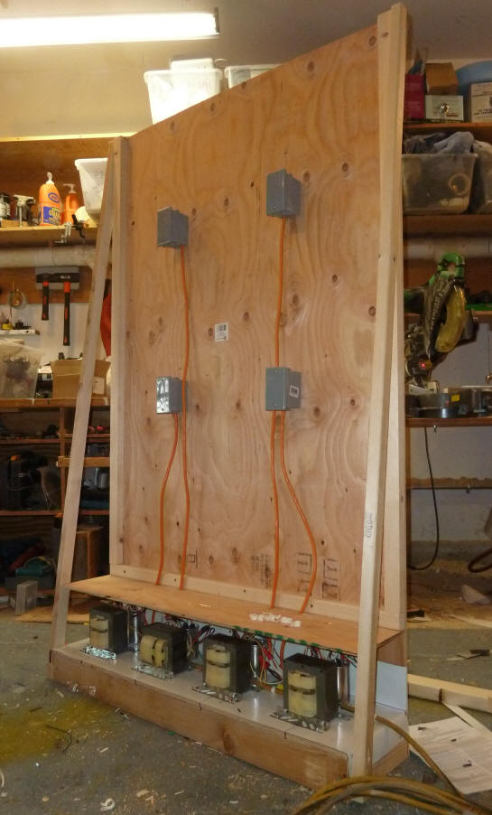
After a bit of thought I settled initially on four of the 400 watt metal
halide lamps mounted on a backing board. The lamp backing board supports
the lamp sockets and the reflectors. The lamp backing board is mounted to
a base box that sits on the floor. The ballasts are mounted on the base
plate, and the weight of the ballasts on the base plate provides a pretty stable
support for the lamp board.
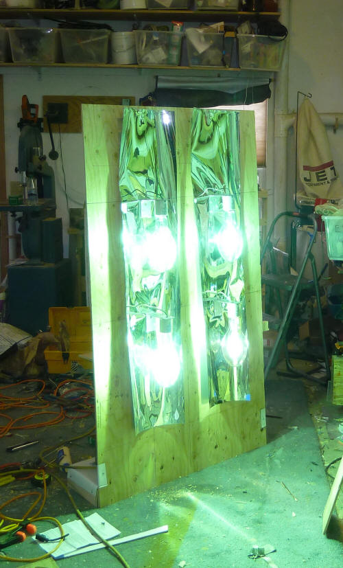
The initial mounting of four 400 watt
lamps on the lamp board.
Its hard to see the lamps because
of the reflector material behind them,
but they are there.
Ballasts mounted at the base of the
light support board. The grey junction
boxes are the connections to the
mogul socket mh lamps, which
are on the opposite side of the board.
The weight of the ballasts keeps the
whole thing steady and stable.
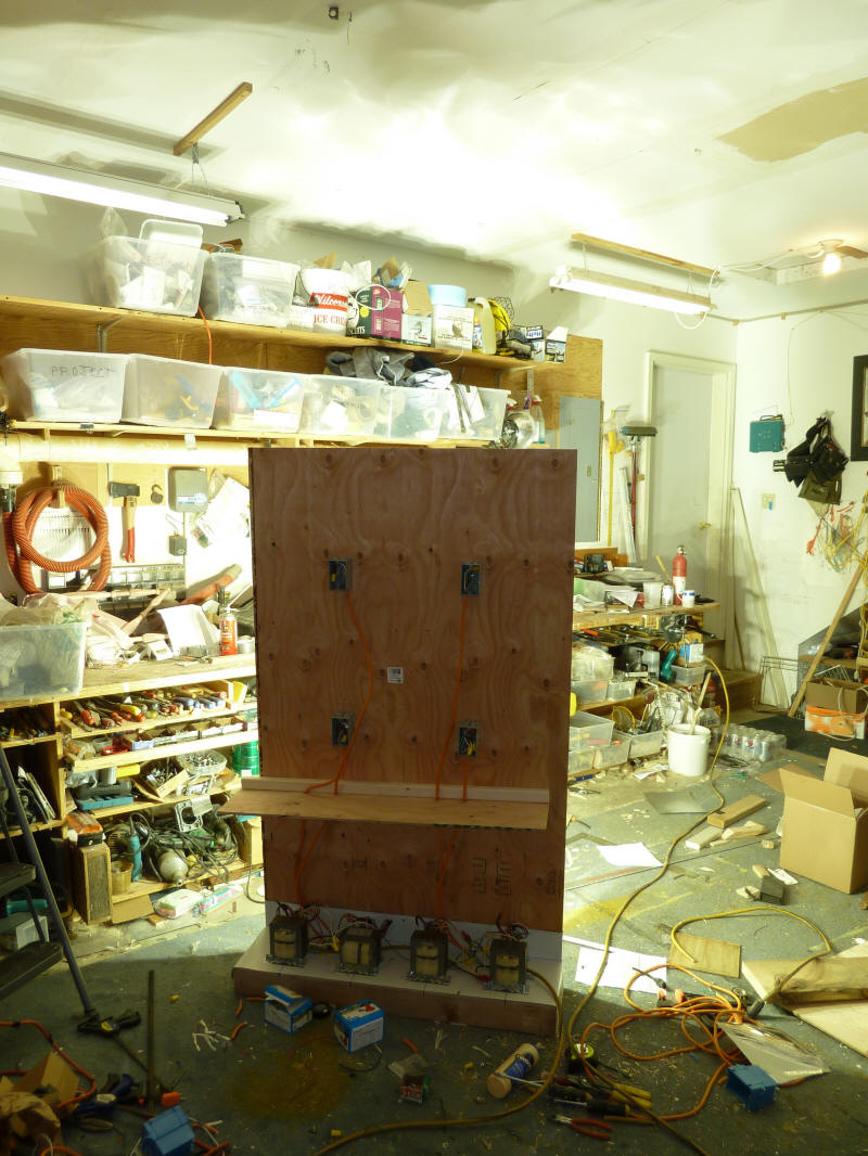
This was the initial arrangement -- see below
for the new arrangement.
Makes a lot of light!
Pulls about 15.5 amps at 120VAC
The pictures just above show the initial arrangement of four mh lamps on the
lamp support board. The idea is that each lamp gets a reflector, and the
whole thing is positioned a couple feet away for the collector under test with
each lamp covering about 1/4 of the collector area. I later decided to go
to 6 mh lamps instead of 4 -- these are on order.
So, this initial setup gave me the chance to experiment with the mh lamps
some -- I have zero experience with them before. Some initial impressions:
- They put out a lot of light :)
- The temperatures around the lamps were cooler than I
expected -- the mounting board runs very cool. Reflectors placed quite
close to the lamps run relatively cool. Having the lamps mounted on a wood
board does not appear to be a problem.
- The ballasts also run fairly cool -- about 170F is the
highest temperature I've measured.
- As expected the lamps take a while to startup, and then
a while more to reach full brightness.
I realize that this mounting arrangement is unconventional, and that there
may be some safety and fire issues. I keep a
careful eye on the whole setup and do not leave it unattended.
I've since decided to go up from four lamps to six of the 400 watt lamps, and have ordered
these. The new arrangement has
six
of the mh lamps which are setup with the lamps oriented horizontally.
The new lamps are the T15 style, which are only 2 inches in diameter. The
combination of horizontal orientation and smaller diameter makes it easier (I
hope) to do more effective reflectors.
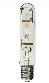
This is the
spec for
the lamp... From 1000bulbs
... (I don't usually recommend companies, but I have to mention
that 1000bulbs.com has been really helpful through two orders of lamps and
ballasts and odds and ends -- real humans who know what their products plus good
prices and fast shipping). The lamp is 1.8 inches in diameter by 9.75
inches long -- 10 bucks a lamp. The lamps produce light by maintaining an
arc through the arc tube that you can see inside the out glass envelope.
The arc length is about 1.5 inches. Each lamp has a ballast that provides
the right arc starting voltages and maintains the arc current at the right level
once the arc is established. The arc operates at about 135 volts once
established. To save money, I bought ballast "kits" which have the ballast
transformer and capacitor, but no case.
The rough logic for using six 400 watt mh lamps providing the needed light levels
is:
- Each 36K lumen lamp will light up an about 18
by 18 inch (2.2 sqft) area -- six of these lights would then light up about 12
sqft -- a bit larger than the planned 2 by 4 ft test collector.
- I would like to be able to produce an illuminance level
equivalent to full sun on the target -- full sun is about 10K foot-candles (fc)
(A foot-candle is 1 lumen per sqft)
- If the full 36K lumen were uniformly spread over the
2.2 sqft target, the illuminance on the target would be about (36K/2.2 sf) = 16K
fc
This is about 1.6 suns, but assumes a perfect reflector, which is not realistic.
- Reflectors are not perfect, and one way to account for
this is to apply a
coeficient of utilization (CU)-- a value of about 0.6 appears to be typical.
The CU is basically the fraction of the light output from the lamp that actually
illuminates the target area -- the remaining part being lost to other areas.
If a 0.6 CU was achieved, the the illuminance would be (16K fc)(0.6) = 9.6K fc,
which would meet the goal of full sun.
So, I ordered the 6 lamps assuming that I could work out a reflector that
achieved the CU of 0.6 and get the 1 full sun on the test collector. That
is proving to be harder than I expected.
I've done these estimates in terms of lumens, which is a unit of luminous
flux that is weighted to the response of the human eye. The collector does
not react to radiation in the same way as the human eye -- it is able to turn a
wider range of light frequencies into heat. But, it is difficult to find
the data on lamps that would allow working over the full spectrum that
collectors respond to, and it seems like if the numbers work out in lumens they
will probably be reasonably close for the collectors thermal response?
Reflectors
A good reflector that puts the lamps light on the target is critical.
Just to illustrate this, if you have a 400 watt metal halide lamp that is
radiating 36000 lumens, that light energy is going in all directions. If
you have (say) a 2 ft by 2 ft target at (say) 5 ft from the lamp, then the
percentage of the 36000 lumens that end up on the target is the ratio of the
surface area of the target to the surface area of the 5 ft radius sphere --
which is (2)(2) / (4)(pi)(5^2) = 1.2% -- so, without a good
reflector, very little light gets to the target where you want it.
Basically the CU without a reflector is about 0.012.
To make the six 400 watt lamp configuration work, I need a reflector that
delivers at least 60% of the each lamps 36K lumens to the 18 by 18 inch target area for
each lamp, and (hopefully) spreads it fairly uniformly.
1 st Try
At first look, a parabolic reflector seems like a good choice. If the
lamp arc is placed at the parabola's focal point, light reflected off the
reflector surfaces will leave parallel to the parabola's center line. So,
if the big end of the reflector is about the same size as the target, it seems
like a perfect match.
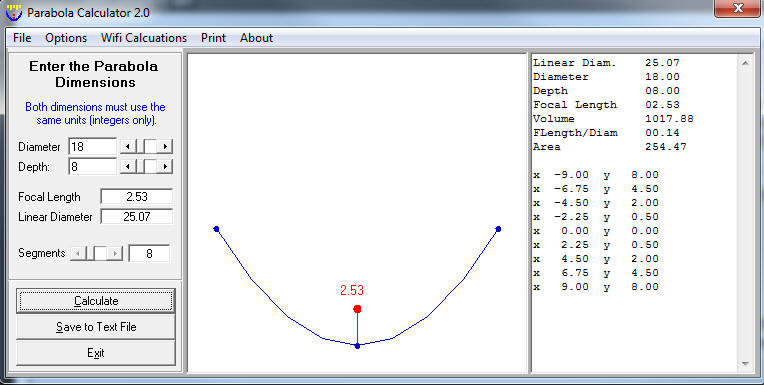
Here is a parabola that is 18 inches wide (to match the target), and 8 inches
deep.
The problem with this is that if the target is about 2 ft away from the
reflector, and the target is 18 inches wide, than a lot of light will escape out
the sides as shown just below. All of the light between the two marked
light rays does not hit the reflector or the target and is just lost.
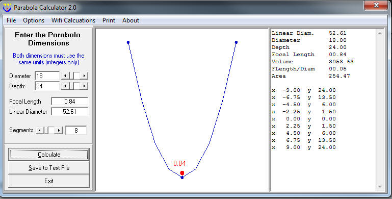
If you make the parabola deeper to reduce this area of lost light like this
24 inch deep parabola:
As shown just below, the deeper parabola greatly reduces the fan of light
lost between the two light ray directions shown. But, the making the
parabola deeper moves the focal point (and lamp arc) such that quite a bit of
the parabola would be inside the lamp glass envelope, which would be tough to do.
The focal point for the deep parabola is only 0.8 inches from the apex of the
parabola, and the part of the parabola near the apex all lies within the lamp
envelope.
This seems to make the parabola not so good a candidate for the reflector?
Am I missing something here?
2nd Try
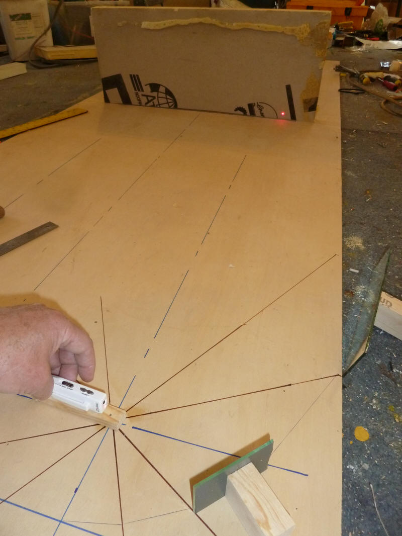
The way I ended up doing the first cut reflector was to layout the lamp on
the board in the picture below. I then drew radials from the center of the
lamp arc location at 30 degree intervals all the way around the circle. I
then set up a laser pointer at the arc location, and positioned a mirror within
each 30 degree segment, and turned it until the laser pointer from the focal
point would reflect off the mirror and onto the target. The 30 degrees is
a fairly close match to the desired target width in that the reflected ray off
one end of the mirror hits the left edge of the target and the reflected ray off
the other edge of the mirror hits the right end of the target.
This is, of course, not an exact method in that the lamp arc is not a point,
but is about 1.5 inches long -- but the idea (hope) was that it was close enough.
lamp arc is located where all the radials meet.
Laser pointer is pinned at the arc location.
The target is the piece of insulation board to the right.
The mirror segment has the small block of wood
attached to it below the laser pointer.
The mirror angle as adjusted for each segment so that
the mirror reflected the laser onto the target.
The laser dot can be seen on the target toward the right side.
This picture has the mirror lines drawn in for the first
few mirror locations.
The mirror layout I actually used is closer in to the lamp then the one shown
in the picture above (see pic below). The first segment lies within the
lamp envelope, and can't be used. I combined the next three 30 degree segments into
one because the angles were close and it would have been difficult to fabricate
these small single segments accurately. By moving the first segments in
closer to the lamp, the big end segments also moved in and got down to about the
same width as the target.
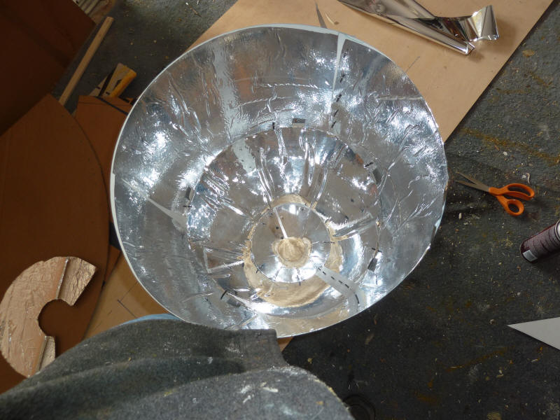
Building the Reflector Prototype
So, I ended up building a reflector with 3 segments that is 24 inches deep,
and 18 inches in diameter at the big end. The hole in the small end is
about 2.5 inches in diameter, and just fits over the lamp with a quarter inch
clearance. See pictures below.
So, each segment of the reflector is a portion of a cone, which can be made
from a flat piece of sheet metal bent around and joined. I laid these out
using the slant lengths of the cone from the diagram on the board. The
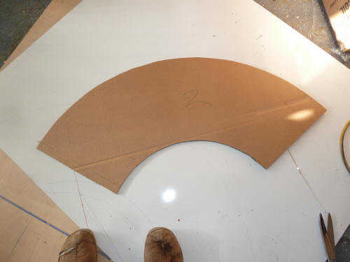
piece for the middle segment of the collector looks like this in flat:
I made a cardboard template for each segment, and then used the template to
cut out the shapes in aluminum flashing sheet.
After the sheet was cut to shape, I glued aluminized mylar to the inside
surface with spray adhesive.
Then bent the flat sheet around into the cone segment and fastened the edges
together with short self tapping screws. I cut the sheet an extra
inch long to allow for the overlap needed for fastening to the other two cone
segments.
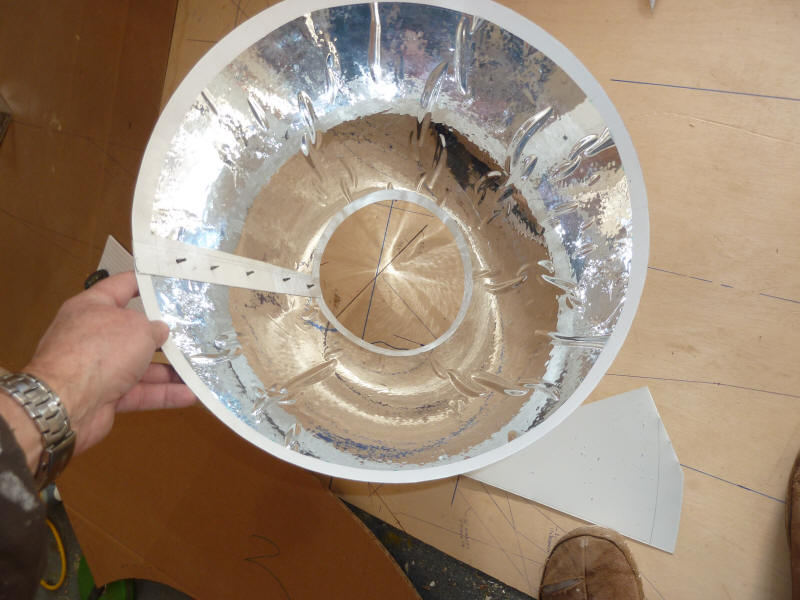
Here is the finished middle segment:
I made the other two segments the same way, and then attached all three
segments together to make the whole reflector.
The gluing job is a bit lumpy, but all in all this way of making the
reflector seems pretty workable and produces a reasonably precise product.
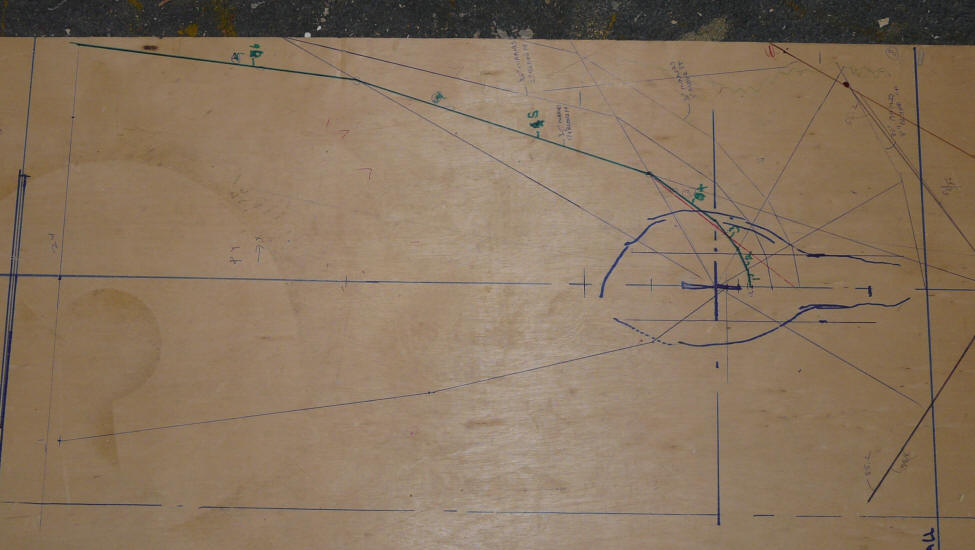
The 2d outline for the built reflector is in the dark green lines -- six 30
degree segments in all. Segment 1 lies inside the bulb, so it can't be
built. The next 3 segments (2, 3, and 4) are combined into a single segment of
a cone on the built reflector as they are close in angle and it would be tedious
to build them as separate segments -- the red line shows the cone frustum
representing segments 2, 3, and 4.
Segments 5 is a separate cone frustum in the built reflector, as is segment 6.
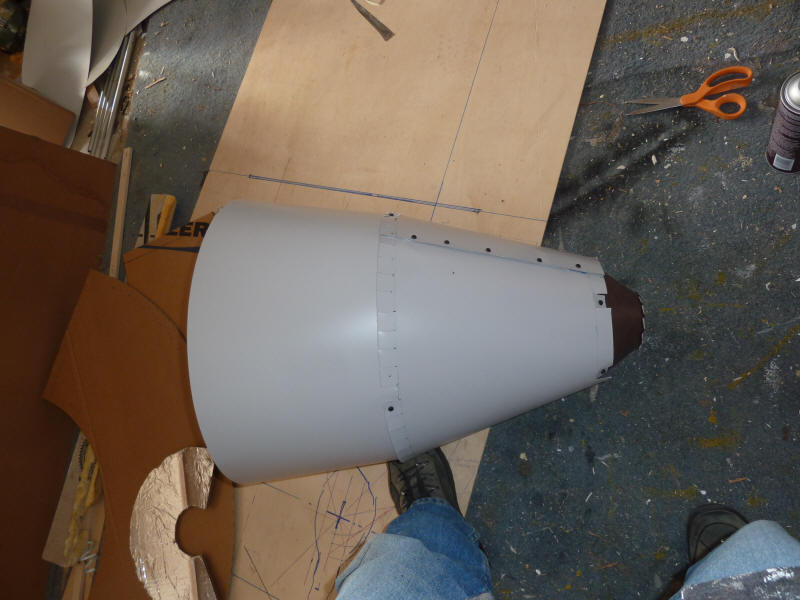
The built reflector. It is made from 3 segments, each is a frustum of a
cone.
The brown cone is segments 2, 3, and 4 from the sketch above.
The middle section of a cone is segment 5.
The right section of a cone is segment 6.
Light Pattern
To get an idea how this was going to work out without building all 6
reflectors, I set up the one reflector on one mh lamp and aimed it at a
simulated collector to see how well the one lamp lights up its 18 by 18 inch
share of the collector. The lamp I used was not the one shown above as
I've not received them yet, but its a 400 watt mh and should be pretty close.
The reflector encloses the lamp, and nearly touches it at the back end -- I
was concerned about what kind of temperatures the reflector might see.
After an hour of operation, the back of the middle segment (hottest part of the
reflector) was at 160F. The smaller segment while closer to the lamp
actually ran cooler at 120F -- so, no really high temperatures. You can
touch any part of the reflector with your hand at least for a few seconds --
most of the reflector is quite cool.
The aluminized mylar seems to be surviving OK. I think that in the final
design, I'll have a bit of forced air circulation around the reflectors and
lamps.
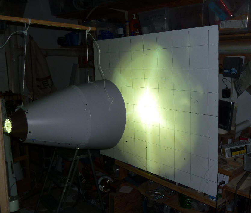
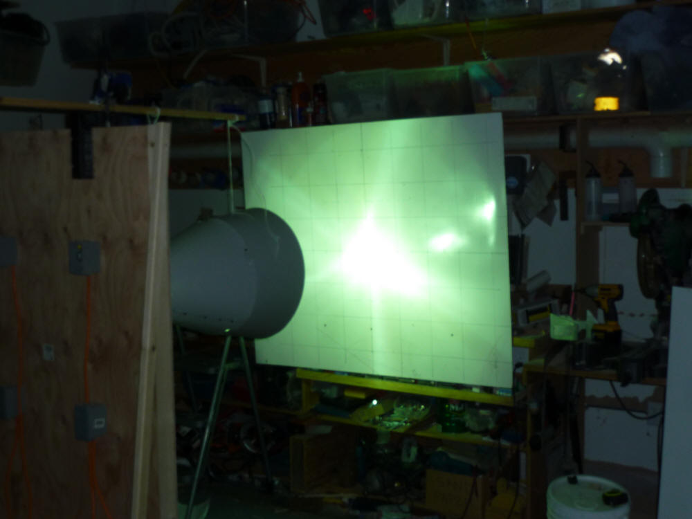
This shows the light pattern on a white board representing the collector.
The squares are 6 inches. The 18 inch target area goal is the blue dotted
line that is a bit hard to see.
These are the light levels measured with a light meter at the grid
intersection points. It should be mentioned that the light meter is
only certified accurate up to 50K lux, and some the readings are twice that, so
there is some question about the accuracy.
The table gives the light levels in foot-candles with the big end of the
reflector 18 inches from the target. So, the light level right at the
center of the grid is 10,480 fc (a bit over 1 full sun).
12 inches
left
6 inches
left
Vertical
Center
6 inches
right
12 inches
right
12 inches
up
1000
6 inches
up
1407
3717
1352
Horz
Center
1208
2462
10480
3643
880
352
6 inches
down
1574
4182
2777
12 inches
down
1040
The big lighted circle has a radius of about 20 inches. Outside the
circle, light levels drop to about 60 fc.
So, looking at the picture and the table -- I'd tentatively conclude:
- While it reaches full sun levels at the center, the
average of over the 18 by 18 target area is substantially less that full sun.
Maybe only about 35% of full sun over the full 18 by 18 area.
- The pattern has a distinct hot area in the middle, but
drops off to much lower values well inside the 18 inch square.
- Spill over from adjacent lights when all 6 are
operating might increase the light levels up to about 50% of full sun.
- Assuming the light is actually operating at 36K lumen
output (an unknown), the CU is low -- maybe only about 25% compared to the
desired 60%.
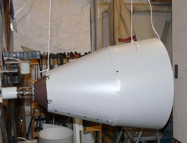
If the "sun" is moved back so that the big end of the reflector is 33 inches
from the target (pic below), the light levels drop substantially. For
example, the center of grid reading drops to 3800 fc.
light pattern with light moved back to 33 inches from the target.
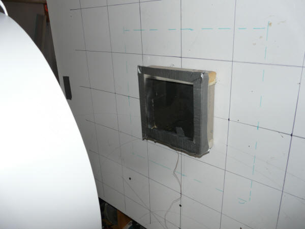
As a way to compare "real" sun to the simulator, I did this little box below.
Its made from insulation board with and absorber of thin (0.01 inch) black
aluminum and a plexiglass glazing. A surface mount thermocouple is mounted
to the back of the absorber. The stagnation temperature that the
thermocouple registers is an indication of the sun intensity. This is not
a perfect system for comparing simulator to outdoor in that the temperature it
registers also depends on the ambient temperature.
For the simulator, the temperature reads 176F with the reflector 17 inches
from the box and the shop temperature at 48F. The other day outside with
full sun (probably about 1100 watts/sm), the temperature read 220F. So,
this agrees with the light meter readings to the extent that it indicates that
the simulator is not quite up to full sun levels.
The stagnation box that compares solar intensity.
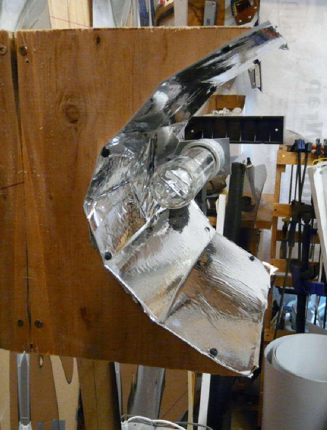
3rd Try
The 3rd try uses a smaller diameter light with a parabolic reflector behind
the lamp to reflect light from the lamp toward the target, and a long light tube
in front of the light to channel light from the lamp toward the target.
The parabolic reflector is about 11.5 by 11.5 inches. It is shallow
enough that the arc tube in the light can be right at the focal point of the
lamp without any cutouts in the reflector to clear the lamp envelope.
The light tube is 11.5 by 11.5 at the lamp end tapering to about 14 by 14 at
the far end.
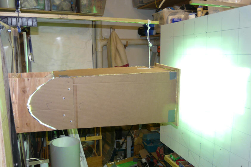
The back parabolic reflector mounted behind the now
horizontal lamp with arc tube parallel to long axis
of reflector. The two end plywood forms keep the
parabolic shape fairly accurately.
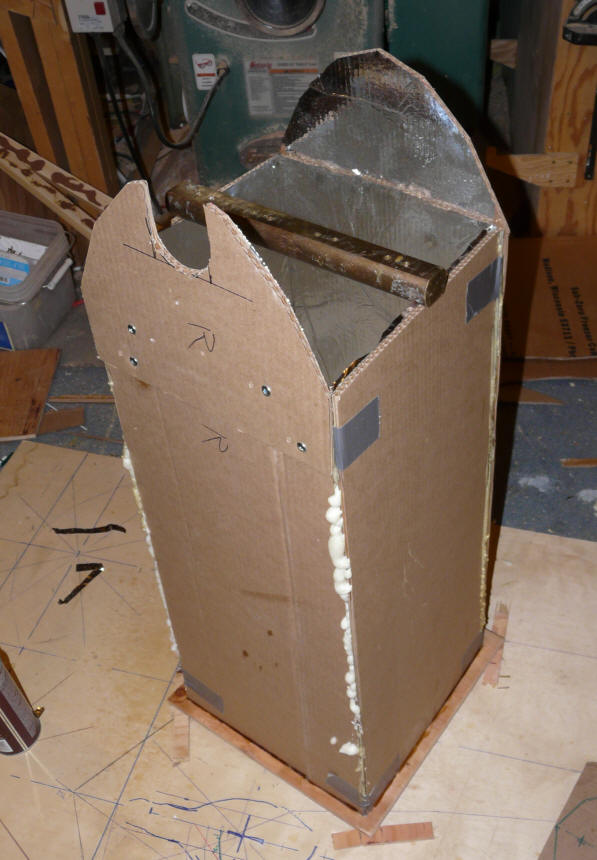
The light tube that extends forward from the parabolic
reflector to channel light from the front of the lamp
to the target. The cutout is for the lamp socket.
This shows the whole works in place and shining on the target. I realize
this is not pretty, but I'll clean it up when I get to something that works.
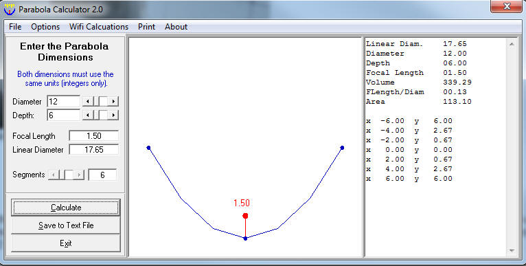
This is the parabola used for the back reflector. It is 12 inches at
the big end, and 6 inches deep. The focal point is 1.5 inches from the
apex of the parabola. The new smaller diameter lamps allow the arc tube to
sit at the focal point without any cutouts in the reflector for lamp clearance.
The long axis of the arc tube is parallel to the long axis of the reflector.
The parabola is relatively shallow because if it is made deeper the apex
moves closer to the focal point and the lamp envelope interferes with the
reflector.
So, the parabola takes light from the back half of the bulb (and a bit more),
and directs it at the target. The side walls that extend toward the target
from the big end of the parabola take light from the front half of the lamp and
direct it toward the target. Without the side walls, a large fraction of
the light from the front half of the lamp would miss the target. Some of
the light off the front half of the lamp requires two reflections to get to the
target.
Because the back parabola is a segmented parabola, the reflected rays don't
come out perfectly parallel to the axis of the parabola, but a little work with
the laser pointer at the focal point indicates that while they may not be
parallel, they generally hit the target, and the few areas that are wide of the
target mostly get picked up by the long light tube and then onto the target.
The arc tube is, of course, not even close to a point light source, so
that further spreads the reflections. The long axis of the arc tube is not
aligned with the parabolic cylinder, which should help.
This setup is working better.
This is the light pattern as measured by the Extech light meter -- in foot
candles -- full sun is about 10K fc:
12 inches
left
6 inches
left
Vertical
Center
6 inches
right
12 inches
right
12 inches
up
6 inches
up
11430
2080
Horz
Center
13580
14560
800
1860
6 inches
down
2510
7990
7160
3070
12 inches
down
The stagnation box got up past 220F and was still going up a bit when I shut
it down -- similar to the values in full "real" sun.
The 18 by 18 inch target area for one lamp is lit up pretty well -- its at
1.5 suns in the middle, and much of it is just above or just below 1 sun.
There is still a hot spot in the middle, but not quite as bad as it was, and
when the other lamps are in, there will be some fill in of the areas toward the
outside of each 18 by 18 area by the other lights. It the hot spot
is still too bright with all lamps in place, I'll try the reflective button in
front of the arc tube that reduces direct radiation from the arc tube to the
center of the target.
This is with the end of the light tube 14 inches from the target -- I can get
to lower light levels by increasing the distance.
The main thing that I like is that the light levels for the first time look
like full sun is achievable -- I think that the uneven distribution is something
I can fix at least well enough to do the job.
So, in the end there would be six of these 400 watt, small diameter lamps
mounted in a 2 wide by 3 high pattern -- each mounted just as this test
one is mounted with a back parabola. Before building the individual
light tubes for each lamp, I'm going to try just a big light tube around the
whole thing as has been suggested. If that does not work, I'll build light
tubes for each lamp.
The reflective material I'm using now is a thin aluminized mylar from
the local Planet Natural. I will probably change to shiny thin aluminum
(maybe just aluminum foil) for the parabola as its pretty close to the lamp.
The temperatures I measured on the back reflector were about 135F max after half
an hour -- not so bad given that its now pretty closed in. Thank goodness
for the metal halides with the lower IR output.
This may take a while as some of the ballasts and sockets are back ordered.
When 1000bulbs.com said they were out of the $3.58 mogul sockets for the lamps,
I tried our local Platt Electric -- they could get them in 2 days for $60 each!
-- decided I could wait.
Want to thank everyone for the suggestions -- I've
used some of them and plan to try more.
If you have any further ideas, I'd very much like to hear them.
Questions/Problems
So, here are the questions:
- What can be done to the reflector design to get a
higher percentage of the lamp light output on the target?
- What can be done to the reflector design to get a more
even pattern of light over the 18 inch square?
- Is there a fundamentally different approach that would
work better?
- Is there a better way to compare real sun thermal
content to simulator thermal content than the stagnation box?
- One question I've not found an answer for on the mh
lamps is that they have to run for a few hours before they come up to full
output -- question is, how many hours, and how much lower is the initial output?
That is, are my lamps with only a couple hours on them not yet up to full
output?
If you know of any successful, low budget sun simulator designs, please let
me know. If you know of any details on how the lamp/reflector designs are
done on any of the commercial or research sun simulators, I'd love to see them.
Any ideas or suggestions would be appreciated. There is a comments
section below, or if you would rather email me directly, I'm at
gary@BuildItSolar.com