Search
The Renewable Energy site for Do-It-Yourselfers
An Idea For a Simple, Cheap,
Efficient Pool Heater
|
Even though commercial solar pool
heating collectors are fairly inexpensive and work well, there seems to be a
strong interest in building collectors. The idea offered below for a
simple DIY solar pool collector could be built for about 1/4 the price of
commercial collectors, and (I believe) can perform roughly on par with
commercial collectors. Please bear in mind that the only thing that I have
actually built is a small 4 ft square prototype to test the idea (I don't have a
pool). So, if you build one for your pool you get to be a solar pioneer --
please let me know how it comes out.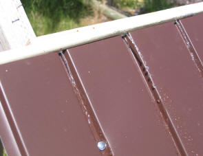
On this page:
|
|
Overview:
This is an idea for a
potentially simple, cheap, durable, and efficient solar pool collector.
Comments are most welcome.
This solar pool heating collector
consists of a sheet of thin metal that is painted a dark color and sloped down
toward the south. The metal has channels or grooves that run from
top to bottom spaced closely. Water from the pool is pumped
to a manifold that runs along the top of the metal collector. The manifold
has a small hole above each groove that delivers a
small stream of water to the groove. The water flowing down the
grooves, picks up heat from the metal areas between the grooves. At
the bottom of the collector, the heated water is collected in a gutter like
arrangement that conveys the water back to the pool. The collector is not glazed.
The collector is similar to a
Thomason trickle collector, without the glazing.
The prototype collector I built
to test the idea is 0.02 inch thick aluminum soffit material that comes painted
in a dark brown. The grooves are preformed in the material by the
manufacturer. The individual panels are 12 ft long and about 16 inches
wide. The panels are pre-finished with what appears to be a durable
enamel, that will (hopefully) hold up to pool chemicals well. While this
collector works well, it appears from the testing that the efficiency
would be a few percent better with more closely spaced grooves. So, I think that
the wave style corrugated metal roofing may work even better (see test results below). I
used the aluminum soffit material because I had some around.
Potential advantages:
-
Its cheap -- maybe $1 per sqft
total (compared to $4+/sqft for commercial pool collectors)
-
Its efficient for the pool heating
application (see below)
-
Its easy to build
-
It should have a long life (but see
below)
-
Minimal maintenance and no freeze
problems
Not yet resolved issues:
You might well ask, how could a
solar collector that is not glazed and has open water channels that would allow
evaporative cooling be efficient?
-
The reason it can be unglazed and
still be efficient is the same reason that most commercial pool collectors are
unglazed. The pool water is usually lower in temperature or near the
same temperature as the ambient air -- this means that the
collector will lose little heat
to the air even without glazing. A further benefit of not glazing the
collector is eliminating the glazing solar transmission losses. This logic works in most climates during the swimming
season, but may not hold true in colder climates early or late in the season
-- in these cases a glazed collector may work better. This collector
could be glazed with polycarbonate (see tests below), but this increases the
price by another $1 per sqft.
-
The reason that the open flow
channels are not a serious evaporative cooling heat loss is that the channels are only about 10%
to 20%
of the area of the collector (see pictures) -- the rest of the collector
surface is dry. A calculation passed on by Nick Pine based on the ASHRAE
handbook estimates that the loss per sqft of water surface under typical
swimming season conditions is about 40 BTU/sqft. Since only 10% of the
collector surface is the water channels, this becomes (40 BTU/sqft-hr)(0.1
exposed) = 4 BTU/sqft-hr. This is a small loss compared to the incoming
solar radiation that is likely to be 250 to 300+ BTU/sqft-hr under sunny
conditions. This is further supported by the test results below for
glazed vs unglazed performance. The tests below indicate that the best
performance results from closely spaced water channels, even though this does
increase the water surface area a bit.
Prototype
Just to get an idea how well the
concept performs, I made a 4ft by 4ft test model from some left over aluminum
soffit material. See the pictures and captions below for the description.
Bear in mind that this was just to test the idea. A real collector would, of
course, need to be larger, and would need more permanent support structure
and manifold details.

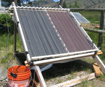
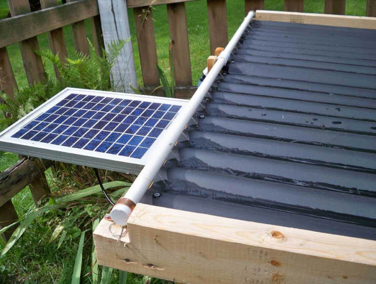
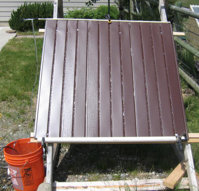
Prototype collector -- water is
pumped from the orange bucket (representing the pool) by a small submerged pump up to the
half inch CPVC pipe running along the top of the metal. This CPVC manifold
has a small hole drilled above each groove in the metal. Each hole
emits a small stream of water into the groove (the water is flowing in this
picture). The water flows to the bottom of the panel where the slotted PVC
pipe running along the bottom picks it up and returns it to the bucket.
Four versions were tested:
-
0.02 thick alum with channels/grooves spaced about
4 inches, water flow in channels only, no glazing
-
Same as 1 with corrugated polycarbonate
glazing added
-
Same as 1
with an additional set of manifold holes between each channel, which put out water
midway between each channel, no glazing.
-
Same as 3 with polycarbonate
glazing
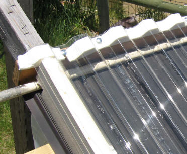
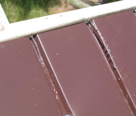
The CPVC manifold distributing water
to each groove. There is a small hole in the manifold just above each
groove. The idea is to keep the water flow confined to the grooves as much
as possible to reduce water surface area and evaporation losses. This is
not a huge issue -- if water flows out over the metal between the grooves in a
few areas, its not a big deal.
Flow rate is about 0.7 gpm for the 14.25
sqft area.
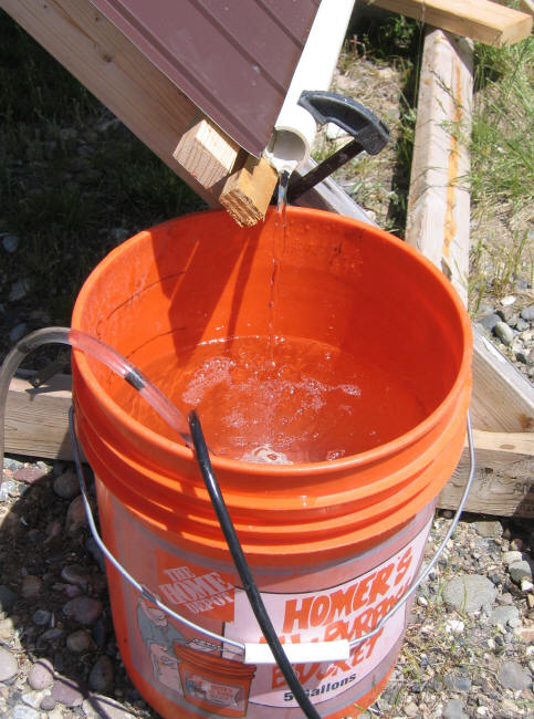
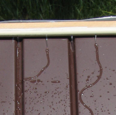
Return flow from collector to bucket.
The submersible pump is sitting in the bottom of the bucket, and pumps water to
the top manifold via the clear plastic tube at the left.
Tests
I did some tests of the four versions
to estimate the efficiency.
The results:
| No |
Description |
Material |
Glazing |
Estimated Efficiency(1) |
| 1 |
Flow in channels, 4 inches apart |
0.02 alum |
None |
0.64 |
| 2 |
Flow in channels, 4 inches apart |
0.02 alum |
Polycarbonate |
0.63 |
| 3 |
Flow in and between channels |
0.02 alum |
None |
0.68 |
| 4 |
Flow in and between channels |
0.02 alum |
Polycarbonate |
(2) |
(1) The efficiency is evaluated when
(Tambient - (Tcolin - Tcolout)/2) = 0, that is where the average fluid
temperature going through the collector equals the ambient temperature.
(2) uncertain due to sun
fluctuations, but probably not as good as the unglazed version.
How the efficiency was estimated:
The test setup is shown in the
picture above. Water from the bucket is pumped by a small submersible pump
in the bucket to the top manifold on collector. Water is collected along
the bottom of the collector with the PVC pipe and returns to the bucket.
Each test started with the 5 gallons in the bucket at around 60F. As the
test progressed, the water in the bucket heated up. The tests were stopped
when then bucket water got into the 90F's. A logger logged the collector
inlet and outlet temperatures, the ambient temperature, and the solar intensity
throughout each test. The solar intensity was measured with an Apogee
Pyranometer. The flow rate was about 0.7 gpm, or about 0.05 gpm per sqft
of collector. See sample plot below.
The efficiency is:
Efic = (Heat to
Pool) / (Solar Radiation Incident on Collector)
The Heat to Pool was calculated as:
Heat to Pool = (Tcolout
- Tcolin) (Flow Rate) (specific heat of water) BTU/hr
Where Tcolout is the collector outlet
temperature, Tcolin is the collector inlet temperature, and flow rate is the
water flow rate in lbs per hour. Specific heat is the specific heat of
water = 1 BTU/lb-F.
Solar Radiation Incident on Collector
was measured directly using an
Apogee Pyranometer.
The 68% efficiency compares to an
average of around 80% efficiency for the commercial collectors that the
SRCC has tested.
There are no doubt differences between the SRCC methods and mine, so I would use
this as a very rough guide only. This collector might be a few percent
less efficient than a commercial collector, but is only about 1/4 the cost --
quite a good bargain in BTU per dollar spent.
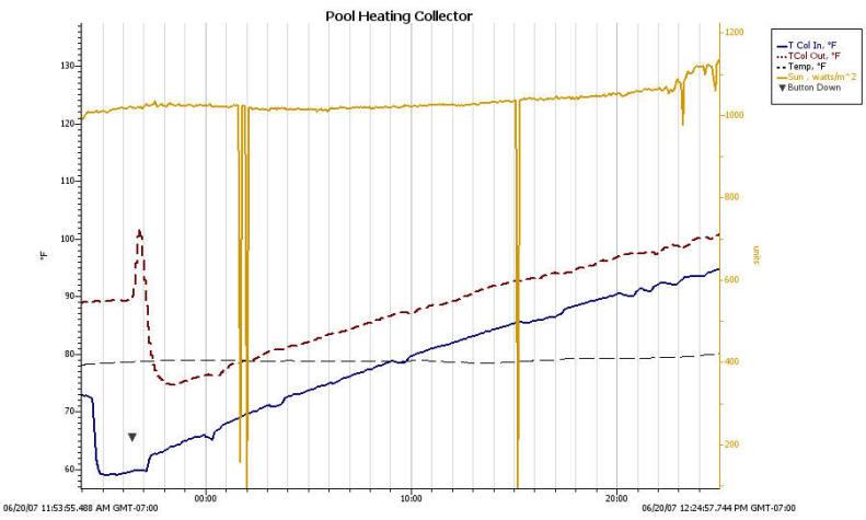
Test plot for configuration 2.
The pool (bucket) water starts around 58F and gets heated to about 95F by the
end of test. Note that the the difference between the collector outlet and
inlet temperature decreases as the water in the bucket warms up -- this is
because the collector losses increase as the water
circulating through the collector gets warmer -- this causes a drop in
efficiency.
The efficiency is evaluated
at the point where the average collector water temperature is equal to the
ambient air temperature -- about 5 minute point on this plot. The grey line is
ambient temperature.
The big drops in solar intensity at a
few points are me shadowing the Pyranometer.
The relative humidity was not
measured, but was likely around 20% -- possibly lower.
Some additional descriptions and
pictures of the configurations tested:
Configuration 1:
0.02 thick alum with channels/grooves spaced about
4 inches, water flow in channels only, no glazing.
 |
 |
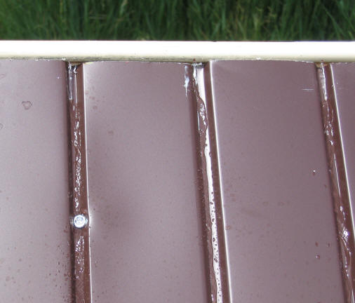
This is 0.02 thick aluminum roof
soffit material with preformed channels spaced every 4 inches. The panels
are 16 inches wide. Multiple panels can be joined together via a joint
that is preformed in the edge of the material -- silicone should be applied in
the joint groove before joining pieces to prevent leaks. The right picture shows the
half inch CPVC pipe spraying a little water into each groove. Spraying the
water only into the groove reduces the open water area and associated
evaporative losses. Typically the surface temperature measured half way
between the grooves is about 15F higher than the temperature at the groove --
indicating that heat loss to the air would be lower if the grooves could be
spaced closer together to reduce the temperature midway between grooves -- see
configuration 3. The water flow rate is 0.05 gpm per sqft of collector.
With this flow rate, the water gains about 10F to 15F as it flows down the
channel. If the flow rate were increased a bit, the temperature rise from
the top of the panel to the bottom would be reduced, and the efficiency of the
panel increased (due to lower heat loss from the cooler absorber). If the
idea that cooler outlet temperatures can make the panel more efficient seems
strange, look here.
Configuration 2:
0.02 thick alum with channels/grooves spaced about
4 inches, water flow in channels only. Corrugated polycarbonate glazing.
This is the same as Configuration 1
except that SunTuf corrugated polycarbonate glazing has bee added over the
absorber to see if the glazing improved efficiency by reducing absorber heat
loss and reducing evaporative cooling from the open water channels. It
turned out that the performance was just about the same as the unglazed version
-- this is probably due to the solar transmission losses of the glazing
offsetting the other gains.
Configuration 3:
Same as 1
with an additional set of manifold holes between each channel, which put out water
midway between each channel, no glazing.
This is the same as Configuration 1
with an extra set of holes drilled in the manifold midway between the grooves.
This was to try and see if having the grooves closer together would result in
better heat transfer from the aluminum to the water, and if this would be enough
to offset the greater evaporative losses from more exposed water surface.
This did result in a significant improvement in performance, and would probably
have done even better if there had actually been another set of grooves instead
of just letting the water flow randomly over the fin surface. Based on
this, I would be inclined to say that the wave style corrugated roofing material
with the corrugation valleys spaced closer together would perform better than
this soffit material with the grooves spaced at 4 inches.
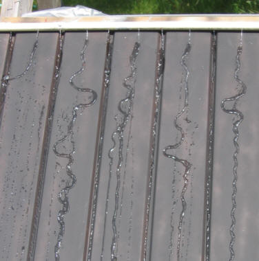
| |
Note that
the streams between the grooves tend to wander around, and sometimes
just divert over to an adjacent groove. Solar Mike from NZ
suggested that applying a bead of silicone down the metal where you want
the water to go. Mike says that the water will follow the silicone
bead very nicely. This would allow using flat metal
sheets with no grooves at all. Thanks Mike!
|
Configuration 4:
Same as 3 with polycarbonate glazing
This is the same as Configuration 3,
but with corrugated polycarbonate glazing added over the absorber. This
tested to a lower efficiency than Configuration 3, but there was some variation
in sun intensity due to some high clouds coming, so I am not showing an
efficiency number.
Heating
Performance:
Here is a rough cut at how much heat
output you might get from this kind of collector, and how much it might warm up
a typical pool.
A 16 ft diameter round pool has an
water surface area of 200 sqft (Pi*8^2). If it is 3 ft deep, then it has a
volume of (200 ft^2)(3 ft) = 600 ft^3, or about 37000 lbs of water.
A collector with an area of one half
of the pool surface area would be 100 sqft.
Using the 68% efficiency from the
test above, this 100 sqft collector might collect about:
Qcollector = (100
sqft)(2200 BTU/sqft-day)(0.68 efic) = 150000 BTU/day
Where 2200 BTU/sqft-day is typical
sunny day radiation on one sqft of collector for one full summer day.
If all this heat went into warming
the pool, it would increase its temperature by:
dT pool = ((150000
BTU/day)/(37000 lbs) (1 BTU/lb-F) ) = 4 F in a day
But, not all the heat goes into
increasing the temperature of the pool water -- some goes into offsetting the
pool heat losses. You can minimize the losses by using a pool cover.
Since most of the pool heat loss is from the surface of the water, the pool
cover might cut the pool heat loss in half. If the pool is in the sun,
then a solar pool cover will collector additional solar heat during the day.
The 150000 BTU from the collector is
equivalent to burning 2 gallons of propane (worth about $4 around here) in an
82% efficient heater. This gives a payback of about one month if you
can build the collector for a bit over $1 per sqft.
Construction thoughts:
I don't have a pool, and I
built this small prototype just to see if the idea works. If you plan to do a
full sized collector to heat an actual pool, here are some thoughts on the construction --
based on no real
experience whatever.
The metal soffiting or roofing that
is used for the collector absorber will
need to be supported along the top and bottom, and probably at intervals along
its span. A simple rack from treated lumber with horizontal purlins to
support the metal panel would be one way to go. It might also be possible to
use an existing fence, building, or roof for part of the support. When
setting up the support structure, bear in mind that the top manifold must be
very near level, and the bottom gutter must slope down slightly to the
collection sump. The joints at the edges of the roofing or soffit panels
may require sealing with silicone to prevent leaking.
You can use one of the calculators on
the pool page to estimate the size of the
collector you need to heat your pool. A very, very rough rule of thumb is
that the collectors should be half the surface area of the pool -- about 100 sqft
for a 16 ft diameter round pool. Remember that a pool cover is a must to
reduce heat loss.
The collectors should ideally be
tilted at an angle that is approximately your latitude minus 15 degrees.
So, if you live at 40 degrees latitude, an ideal tilt would be about 25 degrees.
The tilt angle is not critical. Tilts anywhere from near 0 degrees (flat)
up to an angle equal to your latitude will give good solar performance. You
do need enough tilt to make the water flow down the panel. The
panels should ideally face south, but anywhere between SE and SW is fine,
especially for panels with a low tilt -- even low tilt panels facing east or
west would probably be OK. The panels should be
positioned where they will be in sun at least 6 hours a day. If you are at
all in doubt about things that may block the sun, then do this
solar site survey.
I would pay careful attention to
protecting the metal from rust and corrosion. The pre-finished paint job
the panels come with should be durable, but anyplace you drill holes or cut the
sheets should be protected.
The manifold along the top of the
collector is quite sensitive to tilt. I would drill all the water
distribution holes, then clamp the manifold in place so it level. Then
hook up the pump to the manifold, and make sure the water is coming equally out
all the holes -- if not, adjust the manifold tilt until you get an even
distribution -- then permanently fasten it. Long manifolds should probably
be fed from the middle, or, maybe even at multiple points.
The gutter along the bottom needs to
have a slope toward the sump -- maybe 1/8 inch per foot?
I would test the flow with a garden
hose before permanently attaching it.
The gutter could be a 2 or 3 inch
diameter PVC pipe with a slot cut in it that is just wide enough to allow the
metal to fit into it. This is probably better than
an open gutter from the standpoint of reducing evaporation heat losses.
The gutter in the prototype pictures is made this way. When building the
support structure, remember that half of the diameter of the gutter is on each
side of the plane of the sheet, so the gutter support will need to be set back a
bit.
If the pool pump is used to circulate
water through the collector, then a way needs to be worked out to get the pool
pump to pick up water from the collector sump. This may
involve installing a check valve in the line from the sump to the pump intake
line to insure that the pool does not drain into the collector sump? I
don't know much about pool pumps -- if someone knows a good way to do this,
please let me know.
The pool pump also needs enough
pumping head capability to lift the water to the collector manifold -- most pool
pumps should be OK for this.
If the bottom of the collector can be
placed above the pool surface level, then no return sump is needed, the water
from the gutter can just be piped back to the pool by gravity flow.
You could also use a small dedicated
pump to circulate water through the collectors independently of the pool pump.
It should be rated at about 0.05 gpm per sqft of your collector area -- so, 5gpm
for a 100 sqft collector. It should be rated to produce this flow at a
head of at least the vertical distance between your pool water surface and the
manifold -- allowing for some extra head to overcome pipe resistance is a
good idea.
In any case, you need to have some
means to insure that water is not circulated through the collectors when the sun
is not shinning on them, or you will end up with a pool cooler instead of a pool
heater. A timer might do this if your weather is
consistently sunny during the swimming season. A differential controller
would be even better, but adds some expense and complication.
If you build one of these please let
me know how it all goes --
Gary.
Matt has done a really nice job of building and documenting a
collector based on this design:
Its done with corrugated metal roofing as the trickle down absorber.
Its nicely integrated with the pool, and uses a solar powered pump, so
there is no power use at all.
The 64 sqft collector heats his 25 ft diameter in ground pool nicely.
Cost of the collector along worked out to only $1.80 per sqft.
Matt's Open Flow Solar
Pool Heating Collector... |
Alternative DIY Collectors:
There are some other potential
homemade collector designs listed here in
the "Homemade Pool Heaters" and the "Something Else to Try?" sections.
Of these, the coil of black plastic
pipe is by far the most common. I think that these pipe coil collectors
can work, but it will probably require a lot of pipe to work well. If you
take the sample 100 sqft collector mentioned above, it would take a length of 1
inch outside diameter pipe of about 1200 ft long to have the same 100 sqft
exposed area. This is certainly possible, and I have seen pictures of
collectors which appeared to have something of this order laid out.
It does take a fair amount of space. The cost might be around $2.50 per
sqft. Its a nice simple design that might be well suited to some
situations. If anyone has experience with this type of collector or has
taken some performance measurements, please let me know --
Gary.
I saw a picture of one pool collector
that consisted of a piece of black poly film laid out on a slope just above the
pool and extending to the pool edge. A hose delivered water from the pool
to the top of the plastic film, and the water ran down the film picking up heat
from the black poly and then drained back into the pool. I am
guessing that this actually worked fairly well if the water was distributed
evenly over the film -- this is how simple pool collectors can be :)
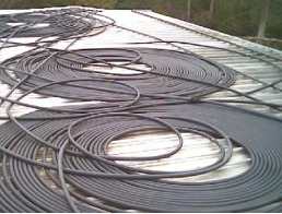
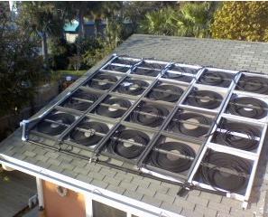
The pipe coil pool collectors shown
at the right are some pictures found on the Internet with no real explanation.
Gary 6/17/2007