
Search
The Renewable Energy site for Do-It-Yourselfers
Residential Renovation of a Schoolhouse
A Deep Energy Retrofit
1 Year Report
The material below is Gordon's report
on how things have been going in their energy retrofit of a
schoolhouse into a very energy efficient home after about 1 year.
Gordon gives a summary of the thermal performance to date, as well as some fixes
to minor problems with the retrofit.
While Gordon is inclined to be modest
about it, it seems to me that the house is performing very well indeed, and that
Gordon's spreadsheet thermal analysis proved to be very close -- no small
accomplishment.
Note that in addition to the 1 year
report below, Gordon has provided an updated copy of the
thermal analysis spreadsheet...
I'd like to thank Gordon and Sue once
again for the great energy retrofit and for the excellent documentation!
For the full story
on the original project...
From Gordon:
Schoolhouse – Deep Energy Retrofit -- 1 Year Report
Several months have passed since the
original article was published. Perhaps it is time that we provided an update
of the thermal and energy performance for you and your website-readers. The
following text summarizes both our performance and various ‘fixes’. The
spreadsheet has been modified to include summer 2009 data, and extended for a
second year’s data (includes fall 2009 at this time). I’ve tried to clarify a
few labels, but otherwise it’s pretty much unchanged.
While the spreadsheet displays data in a
September to August format, we received occupancy late in November 2008. Prior
to that, varying numbers of construction workers lived on site – both in the
dwelling and in on-site trailers. As a result, the fall data (particularly
electricity) was not representative. In the text below the ‘first year’ is
identified as 1 Dec 2008 to 30 Nov 2009.
Background
Before describing the details of the
energy and thermal performance, perhaps we should reiterate the major goals of
our renovation. Being retirees, we wanted a comfortable and casual dwelling,
with low and predictable maintenance. We wanted to eliminate stairways - but we
felt that the lowering of our overall operating costs was paramount. Beyond
that, we wanted to be less vulnerable to the seemingly out-of-control escalation
of most operating costs. This led to thoughts of simplicity, flexibility and
making use of available solar. The recent extreme variability in the cost of
fuels, plus the implications of extended power outages such as the ’98 Ice Storm
suggested to us that we should not be overly dependant on any specific fuel –
even including solar.
Thus we never had the goal of designing
and constructing a solar home. Nor did we intend to create an ultra low energy
home. Nor specifically a ‘Green’ home. These other goals would probably have
led to a higher solar fraction, near net-zero, or healthier environment. We
were striving for a practical retirement home, something appropriate to our
needs. We are indeed pleased with the result – and the solar fraction, the
energy consumption, and thermal performance aren’t all that bad.
- First Summer’s Performance (2009)
In the original article we had mentioned
that a requirement for summer-time air-conditioning was not expected, and thus
no provision was being made. We probably should have mentioned that for most of
southern Ontario, while it is indeed a ‘cold climate’ for building design
purposes, some provision for summer-time air-conditioning of dwellings is very
common. Almost all commercial buildings have air-conditioning. While winters
are long, summers tend to be hot and humid. In many areas, we tend to joke that
there is barely three weeks between furnace shutdown and air-conditioning
turn-on (and vice-versa).
It has proved correct that
air-conditioning will not be needed. In May, we shut down the HRV and began
opening windows. Over the winter, the temperature of the outside masonry walls
had dropped about ten degrees F. The warming of these walls over the summer
actually mitigated interior temperatures – peaking at about 75 degrees F for
less than a week. I was afraid that there might be some condensation on the
mass – but none was evident (condensation had definitely been an issue with the
un-insulated slab floor of the original dwelling). The first half of the summer
was cooler and wetter than normal, and the exterior mass walls were still quite
cool. By August, I was worried that the walls wouldn’t warm up enough, and
contemplated engaging the solar air heater in the solarium to heat the main
house -but August and September were warm and quite sunny and the walls warmed
right up – false alarm!
I should mention that throughout the
summer, we made no effort to manage ventilation and temperature of the main
house with the windows. We tended to have three small (cross-ventilating)
windows open from 1 May to 1 Oct and perhaps one or two more for a few weeks
mid-summer. Half the operable windows in the main house have never been open.
Regarding the solarium, we did have the
sliding patio doors partially open much of the summer – but it never got
un-comfortably warm. The trick really seems to be having two or more open
doors. In our experience, there is far more ventilation with two doors each
partially open perhaps three inches, than one wide open. We never did get out
the ladder to open any of the upper clerestory windows.
- First Twelve Months’ Energy and
Thermal Performance (1 Dec. 2008 to 30 Nov. 2009)
With the construction winding down in
Nov.2008, and our occupancy commencing, the hydro (electrical utility) meter
finally had a chance to come back to earth. A full year of occupancy has
elapsed, and we can now report a little more accurately on both our total energy
usage and our space heating performance.
Solar Recoveries:
Developing an accurate prediction of the
expected solar recovery was one of the most difficult aspects of the design.
There are several sources of aggregate data for this area, but little
correlation, neither in aggregate nor monthly distribution. The equivalent of
U.S. TMY seems to be lacking. So, while we predicted 36.1 M Btu potential solar
recovery and 29.5 M Btu usable, we really didn’t know whether it was reasonable
or not – and certainly had little idea as to the year to year variance (and
still don’tJ).
By our admittedly crude measurements, we figure we recovered a potential of
about 37.5 M Btu (30.6 M Btu usable) over the first year (about 4 % more than we
predicted) – but . in all honesty, this is probably a pure coincidence or luck.
Our spreadsheet predicted the solar
fraction to be about 49.3% of the total net space heating requirement. We
estimate the first year solar fraction to have been about 50%. The actual
calculation is somewhat dependant upon (i) the actual total heat load – which we
expect to be 1 –2% greater than predicted due to the cold winter, and (ii) the
internal and HRV recoveries which were likely lower than predicted due to
slightly reduced occupancy.
Propane Usage:
On 30 Oct. 2009 our propane supplier
refilled our tank. Thus our total propane consumption for both the kitchen
stove and living-room fireplace was 62.1 litres ( $ 40.30Can
) since the previous fill of 12 Dec. 2008 (10 1/2 months). As a result, it has
now been possible to refine our previous spreadsheet estimates for propane
consumption. For that period, a better estimate would appear to be 24.8 litres
for space heating and 37.3 litres for cooking. For cooking, propane use was
only about 0.95 litres per week – but we spent a significant amount of time on
the road slowly moving our possessions. As a result, for the coming winter, we
will estimate cooking consumption to be about 1.20 litres propane per week.
Purchased Space Heating:
Over this one year period, total space
heating consisted of 2784 lbs of wood (or 0.8 bush cord), 25.1 litres of
propane, and 36.3 kWh of electricity for a total gross site consumption of 18.17
M Btu. The resulting effective net space heating requirement was 13.13 M Btu
(or 3848 kWh). With the dwelling being 2506 sq ft (interior net) and the
winter 7152 DD F., the first year net space heating requirement was 0.73 Btu per
sq ft per DD64F (or 4.28 W per m2a per DD17.8C).
In recent years, (and for good reasons)
the work of the PassivHaus Institute is gaining acceptance. In all honesty
though, our designs were undertaken, committed and contractors engaged even
before we had seen any PassivHaus literature. We just wanted a comfy house –
and the renovation was darn near complete before we realized their performance
goals weren’t all that much different from our own.
The above first year space heating usage
translates to 16.99 kWh / m2aTFA – quite good, but certainly not meeting the
PassiveHaus Inst. criteria of 15 kWh / m2a. While the actual space heating
consumption was 13.3% higher than the PassivHaus criteria, the slightly colder
than normal weather last winter could be expected to account for about 5%.
It is noted that the average first year
space heating performance of the PH CEPHEUS Hanover/Kronsberg project was 14.9
kWh/m2a. Nearly half of the 32 townhouse units didn’t meet the criteria either
– some were double the consumption! However, over the first three years, the
average consumption dropping from 14.9 to 12.8 kWh/m2a - presumably due to
resolving construction difficulties and possibly weather warming trends of that
time and area. If over time, our space heating performance were to show a
similar trend, our usage may well meet the PassivHaus criteria.
The PassivHaus criteria was originally
developed for Germany, and is gaining advocates, if not acceptance, in many
parts of the world. Note that this criteria does not take into account the
severity of climate (ie: heating/cooling degree days). As it is unreasonable to
consider that all people of earth have an equal opportunity to reside in the
optimally temperate portions of the world, there is some support for a
performance criteria that gives consideration to the degree-day principle. If
the relative severity of our winter was recognized, our retrofit would have
significantly better performance than their standard.
Total Site Energy Consumption:
Total site energy consumption (excluding
passive solar and recoveries) was 16,100 kWh for the year.
Total Source ( or Primary) Energy
Consumption:
Total source energy consumption for the
first year was 18,800 kWh. The low level of source energy is primarily due to
the efficient use of low footprint, sustainably harvested, wood heat. This
translates to a total source energy use of 83.2 kWh per m2a TFA, or about 70% of
the PassivHaus limit of 120 kWh / m2a TFA criteria.
Further Modifications:
Repair of Insulation Deficiencies:
As discussed in the original article,
there had been two small areas in the attic that had no insulation for last
winter. The area of steel decking exposed to the cold was only about 15 sq ft,
but the thermal loss was rather significant - as the cold was measurable 8 to 10
feet beyond the exposed steel. This has now been rectified. One hole has been
filled with XPS foam and sealed with “Great Stuff”.
The other hole was around the chimney
of the masonry heater and required a little more thought due to (i) Fire Code
clearance, (ii) material fire rating requirements, (iii) the need for
expansion/contraction provisions between chimney and ceiling, and (iv) minor
moisture issues arising from wind driven rain and condensation. In the end, we
filled the area above the masonry chimney and around the SS manufactured chimney
to a depth of 6” with a fireproof mixture of vermiculite, clay and water (about
10 to 2 to 1 by volume). Clay was chosen because it acts as a binder for the
vermiculite and can withstand some moisture repetitively. When thoroughly dry,
several mineral fibre batts (“Roxul”) were laid over the area.
Replacement of Exterior Shrouds (HRV):
In this area, high winds are rather
common during severe weather. The original HRV exhaust shroud had no damper,
and in strong winds, the flexible duct was measurably cold even through the duct
insulation. The plastic shroud has been replaced by a more robust aluminum
shroud that has a relatively tight fitting exhaust only flapper.
We were not impressed with the HRV’s
inlet filter. It caught insects, but little of the dust from nearby farming
activities. We wanted an inlet filter with four levels of filtration – course,
medium fine and electrostatic– but we also wanted them washable for extended
life. The original filter in the HRV is only about 9” by 9” square. The air
resistance of the new filter stack would clearly degrade the blower performance
in the HRV. We decided to remove the HRV filter, and replace the original
exterior air inlet shroud with a fabricated wooden box using spare siding
materials. In this manner, we could build a multi-stage filter about seven
times larger than the original, and clean-up the air outside - before it enters
the ducting. At some point, we should recheck the balance of the HRV duct
flows, but it seems to work as well, if not better than before.

Additional Dampers for the Kitchen
Stove Exhaust:
In advance of the start of last winter,
we selected a spot on one wall central to the house as a representative location
to consistently measure interior house temperature for data logging purposes.
Yep, Murphy was an optimist! As winter commenced, we began to notice that the
temperature readings were somewhat cool – but we were comfortable! As winter
progressed, this became considerably more so. Sure enough, a relatively large
area around the kitchen stove was noticeably cool – right in the middle of the
house! This area included the bath tub/shower stall in the main bathroomL.
The range hood had no integral damper, but at the roof level, the outer shroud
contained a gravity type lid damper. We soon discovered that with any type of
breeze, the damper would oscillate. During more severe weather, it just
remained open for extended periods!
Come spring, we examined the situation
in more detail. Under certain wind situations, rain could penetrate into the
shroud. Moisture would then drain down the vent stack - collecting on top of
the range hood L.
Under certain quick cooling situations (early evening after sun-down),
condensation could arise on the outside of the duct (inside the attic), and
sometimes on the underside of the panel steel roof – which could then run down
the outside of the stack. The result was slight puddling on the floor of the
attic, which is sprayed in-place foam. Some of this water then drained down the
seam in the duct dripping onto the top of an interior concrete block wall. Over
time, moisture had spread through a considerable area of this wall complexL.
In a nutshell, we needed a good damper
for the air, but we had moisture running down both the outside and inside of the
stack- moisture that would be prone to freezing that would disrupt a damper!
The solution took a bit of tinkering:
- Note that all joints were silicon
sealed for water proofing and pop-riveted for strength.
- The original vent stack through the
attic was light-weight 6” diameter aluminum.
- A scrap of aluminum vent pipe was cut
to a 10” by 14” rectangle, and then rolled into a tube about 4” in diameter, 10”
long with a loose, but lapped side seam.
- A common 4” dryer damper was affixed
onto the top end of this 10” piece of four inch vent pipe
(ie: oriented for air to exit tube at
damper).
- A 6” to 4” reducer was installed over
the tube from the lower (other) end, such that the damper was located inside the
taper, near the 6” end. Several small holes (perhaps 3/16”) were drilled
through the reducer in the taper near the 4” diameter (lower) end. Held with
the damper upwards, one can see that upward flowing air would open the damper,
and additionally, downward running interior water would be caught by the tube,
yet the small holes would allow the water to drain to the outside.
- A second 6” to 4” reducer was
installed beneath the first one, oriented in the same direction, almost touching
one another, and both fastened to the tube. . In this manner, water running
down the outside of the stack (ie: the first reducer) would be caught by this
second reducer. Prior to installation, a 1” plumbing fitting was fastened into
a hole in this second reducer near the base of the taper. Thus all water, (both
running inside and outside the stack) would drain out to this fitting.
- A third 6” to 4” reducer was installed
near the bottom of the 10” tube, oriented in the opposite direction.
- A second 4” dryer damper was installed
on the lower end of the 10” tube, inside the taper of this third reducer. The
damper was oriented the same as the first, such that air entering this lower
damper would exit the first damper.
- The length of this assembly was
measured and a slightly shorter section of the original vent stack was removed.
- The assembly was mounted into the vent
stack.
- Chunks of scrap “Sonotube” were cut as
forms and the vent stack and assembly was slowly (~8” every other day) insulated
with “Great Stuff” from the attic floor, up to the water drain outlet.
- A tube for the water drain was then
installed.
- The circular gap that collects the
exterior water was masked with tape, and the foam insulation was extended up to
this gap.
Thus we now have two dampers within the
vent stack and one at the roof level. The dampers now only very briefly open in
a very major wind gust – but readily open with the range hood on low volume.
The moisture problem has been resolved, and the house is now noticeably
tighter. Hopefully warmer – we’ll see.
It is cautioned that this type of
procedure is not likely in conformance to most codes, as it reduces the kitchen
vent stack diameter – but commercial products simply do not address the
situation.
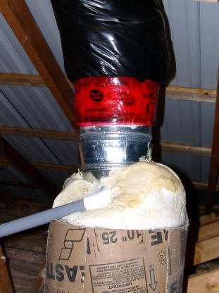
Damper for the Main Plumbing Stack:
Even though the ensuite bathroom has a
small window and an exterior wall (no plumbing in that exterior wall), the
thermal analysis indicated that due to the mass and level of insulation, no
special provision for heating would be needed. However, the plumber chose to
locate the main plumbing stack directly behind the back wall of the bath/shower
stall. Additionally, the contractors chose to not properly insulate either the
hot/cold pressure lines nor the vents and main stack.L
In hindsight, this is absolutely
unacceptable for a low energy home. One does not want condensation from the
cold lines within the walls – insulate them! Once one starts to consider every
BTU, insulating, to minimize the hot water line loss, becomes more practical.
However, an un-insulated stack and associated vents might as well be considered
a 4” hole in the wall right into your shower! In some jurisdictions, a minimal
quality of insulation for about 10 feet is suggested but not enforced. For a
low energy home in our climate (7150DD F), we would suggest a quality level of
insulation for double that distance! The implications of not doing so are
simply dam uncomfortable!
Correcting the situation properly
afterwards is often impossible. In our case, it’s not just the messy matter of
removing drywall from the adjacent room, but additionally tearing down a double
blocked load bearing concrete masonry wall too! A proper repair is just not an
option.L
A damper on the main plumbing stack might lower the thermal loss by a third –
but is unlikely to be acceptable to code. But when faced with the bathroom from
hell, a damper starts to look pretty good!
However, an open rooftop stack is not
just a matter of an oscillating cold air column. It also involves the entry of
a fair amount of snow and cold rain – making thermal considerations worse. It
also means, this moisture must be significantly reduced – as it will wholly
compromise the action of most any damper in freezing conditions. Even if this
externally sourced moisture is eliminated, the exiting sewer gas is very high in
humidity, and could compromise the operation of a damper.
We have tested several different
concepts - all seem far from ideal. The approach used for the kitchen stack is
not feasible in this situation. While it captures internal moisture, it would
allow sewer gas entry into the attic – just not an option! In the end, we
connected two 90 degree vent elbows together to create a “U”. We mounted a
dryer damper between the original stack top and this inverted “U” – turning the
assembly downwind from the prevailing wind direction. In this manner, driven
water is unlikely to compromise the damper, but internal condensation, when
frozen, may prove to be a problem. To minimize this, the exterior of the stack
from the floor of the attic to the roof is being insulated, in an attempt to
keep it relatively warm. But this is not likely to be fully effective. As this
is a trial, it will be necessary to climb to the roof on several occasions this
winter to examine the possible frosting problem. In the meantime, while the
bathroom is not comfy, it is marginally warmer.
|

|
|
The Bottom line, when building or renovating, a quality level
of insulation over the main stack and nearby vent pipes is critically important
for low energy housing in cold climates. Hindsight is 20-20.
Best wishes
Gordy
Gary December 15, 2009