Installing the Differential Controller
You will want to follow the instructions for the particular
differential controller that you buy, but normally the install will
consist of four steps:
- Install a temperature sensor in the collector, and hook this up
to the differential controller. The sensor wants to be mounted
where it will sense the temperature of the tube/fin near the top of
the collector.
This temperature sensor will normally be supplied with the
controller.
For our system, I used silicone caulk to glue the sensor to one of
the absorber fins right next to where the fin meets the tube.
This should be near the top of a riser so that it senses the
temperature of the fluid leaving the collector.
- Install a temperature sensor that senses the tank water temperature near
the bottom of the solar storage tank. The ideal location would
be near the entrance to the U-Tube that leads to the pump inlet.
For the differential controller we used, a sensor was supplied
that was suitable for direct immersion in the tank water. This
is convenient, as the sensor can just be suspended in the tank water
near the entrance to the U-Tube.
If you are working with a sensor that cannot be immersed, you can
enclose the sensor in a length of pipe that is capped on the end and
submerge the tube in the tank. Use silicone to encapsulate the
sensor in the end of the tube to provide better thermal contact and
a additional protection against water.
It may also be possible to just tuck the sensor in behind the EPDM
liner, but you should do this before filling the tank, and be very
careful not to leave any sharp corners.
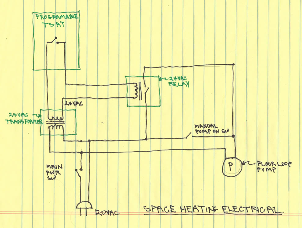
- Connect the pump to the controller. Some controller just
have a regular 120VAC outlet. In this case, just hook up a
line cord with a standard 120VAC plug on it the pump, and plug this
into the controller. If the controller just provides terminals
to hook up the pump to, then run a wire from pump to controller
being careful to follow the instructions for hooking up the line,
neutral, and ground wires to the right terminals.
- Connect the controller to a 120VAC source. If the
controller comes with a line cord and plug, just plug it into a wall
outlet, and you are done. If the controller does not come with
a line cord, its easy to make one by cutting the socket end off an
extension cord, and wiring this to the 120VAC terminals on the
differential controller.
Some of the common differential controller brands are:
Goldline,
Steca, and
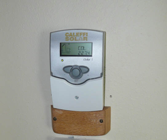
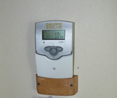
Caleffi,
and IMC. John Canivan and Richard Heiliger at the
JC-SolarHomes.com website
offer a kit or assembled differential controller at a lower price.
I've tested one of Richard's prototypes and it did well and appeared to
be well designed. This
Shem 32 is another imported possibility. I've been using one
of these on my Solar Shed system for this winter, and it has been fine.
Features similar to the Steca and Caleffi. Price is attractive.
And this interesting
myDTC one that looks kind of formidable, but does some logging --
would like to hear from anyone who has experience with it.
If you are using a PV driven pump,
Guy
Marsden offers a differential controller for PV systems ... As
does IMC (listed above). |
Differential controller |