
Search
The Renewable Energy site for Do-It-Yourselfers
Solar Shed --
Controls and Plumbing
|
The controls for the Solar Shed space
heating system are very simple.
Basically, a standard off the
shelf Goldline GL30 is used to control the pump that circulates fluid
through the collectors.
When the pump is off, the
collectors drain back to the tank for freeze protection.
The pump that circulates hot
tank water through the floor loops is controlled by two thermostats.
The first senses whether the house needs heat, and the 2nd senses
whether the tank has heat. If both of these things are true, the
pump is turned on to circulate hot water through the floor.
Basically the plumbing in the
collector loop is all one inch copper and is all sloped toward the tank
for drain back.
The underground pipe to the
house is CPVC insulated with extruded polystyrene rigid foam
board.
More detail and parts below.
Go back to
the main Solar Shed page ...
|
|
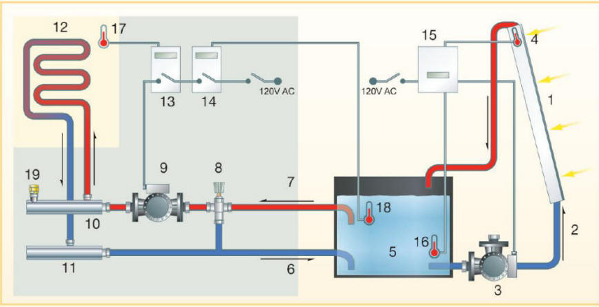
This controls diagram is from the
Mother Earth News article on the system.
The full diagram and labeling are
available
here ...
The full Mother Earth News article on
the system is
available here ...
This is a
more detailed wiring diagram for the pump and controls...
Referring to the controls diagram
above,
For the collector plumbing circuit:
The Goldline GL30 differential
controller reads the temperature of the tank from sensor 16, and reads the
temperature of the collector using sensor 4.
If the collector temperature is
greater than the tank temperature by an amount that you set on the
differential controller, the controller turns on the pump (3).
The pump circulates water through
the collectors (1) as long as the collector temperature remains at least 4F
greater than the tank temperature.
If the collector temperature
drops to less than 4F above the tank temperature, the controller (15) shuts
off the pump (3). The water drains from the collectors back to the
tank -- this keeps water from freezing in the collector and damaging it.
For the circulation through the floor
loops,
For heating, hot water flows from
the tank (5), through the underground pipe (7), through the thermal mixing
valve (8), through the circulation pump (9), and into the supply manifold
10.
From the supply manifold, water
flows out to each of the 6 floor loops of PEX pipe, and then back to the
return manifold (11).
From the return manifold, water
flows back through the underground pipe (6) to the tank.
The function of the thermal
mixing valve (8) is to mix some of the cooler returning water with the
incoming hot water if the temperature of the incoming water is too hot to
circulate through the floor.
The valve is adjustable over a
wide range of temperatures, and prevents the floor from being damaged by
circulating excessively hot water.
Water only circulates through the
floor if 1) the house needs heat, and 2) the tank has water hot enough to
provide heat.
The two thermostats (13 & 14)
turn the pump on only under these conditions.
Thermostat (13) senses the house
temperature, and only turns on when the house temperature falls below the
value you set.
Thermostat (14) senses the tank
water temperature, and only turns on when the tank is above the temperature
you set.
These two thermostats are Johnson
Controls A419s. They will directly control the 120VAC circuit that
powers the pump -- so no low voltage control wiring is required.
Both of the two thermostats are
located together next to the supply and return manifolds.
Thermostat (14) senses the tank temperature via a 150 ft long set of wires
to the temperature sensor located in the tank.
See pictures below.
Plumbing components
15 Goldline
GL30 Differential controller
2
One inch copper pipe between the collector and tank -- sloped toward tank
3
Taco 008 120 VAC bronze circulator pump
16
Temperature sensor -- senses tank temperature for GL30 -- a 10K thermistor
4
Temperature sensor -- senses collector temperature for GL30 -- a 10K
thermistor
5
Tank is an insulated plywood shell lined with EPDM rubber sheet.
6, 7 Insulated
CPVC pipe that runs from the tank to the house.
8
Taco thermal mixing valve
9
Grundfos UPS 15 120VAC circulator pump (probably to be replaced with Taco
008 bronze pump)
10, 11 The supply and return
manifolds. These have connections for up to 6 floor loop circuits in
my case
12
Floor loops of PEX pipe heat the floors when water is circulated through
them
19
Air bleed valve
13, 14 Johnson Controls A419
thermostats to control the pump (9)
18
Temperature sensor that reads the tank temperature for thermostat 14
17
Temperature sensor that reads room temperature for thermostat 13
The manifolds also have valves
and connections for filling the system, and have shutoff valves to shut off
flow between the tank and the manifolds.
The manifolds also have valves
and flow meters that allow the flow in each floor loop to be controlled and
monitored.
I plan to replace the iron
Grundfos pump with a bronze of stainless steel pump -- I used it because it
was on hand. Systems like this that are vented to the atmosphere
should not use iron parts because the air in the system can rust the iron.
The tank collectors and floor
loops all share the same plain water -- no antifreeze.
There are no heat exchangers in
the system.
A heat exchanger may be required
in the floor loop system depending on the elevation of the floor compared to
the elevation of the tank.
Pictures of the Plumbing
Floor Loops:
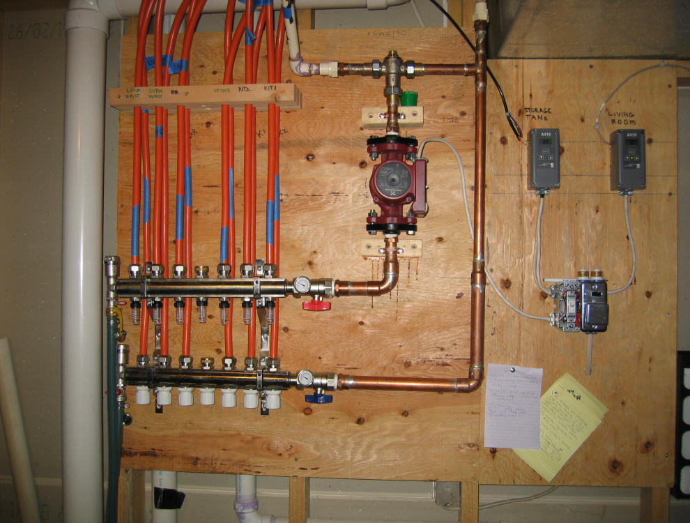
The supply and return manifolds with
the orange PEX pipe running to the 6 floor loops are on the left.
The two Johnson control A419
thermostats that control the system are to the upper right.
The Grundfos pump and Taco thermal
mixing valve (just above the pump) are in the center.
The manifolds were bought as a
package, and include a number of helpful features: fill valves, air bleed valve,
supply and return shut offs, supply and return temperature gages, and individual
flow valves and flow gages for each floor loop -- this makes the system much
easier to fill and troubleshoot.
The fused switch to the right turns
power off to the whole system. The switch right next to it turns the pump
alone off (for troubleshooting mostly).
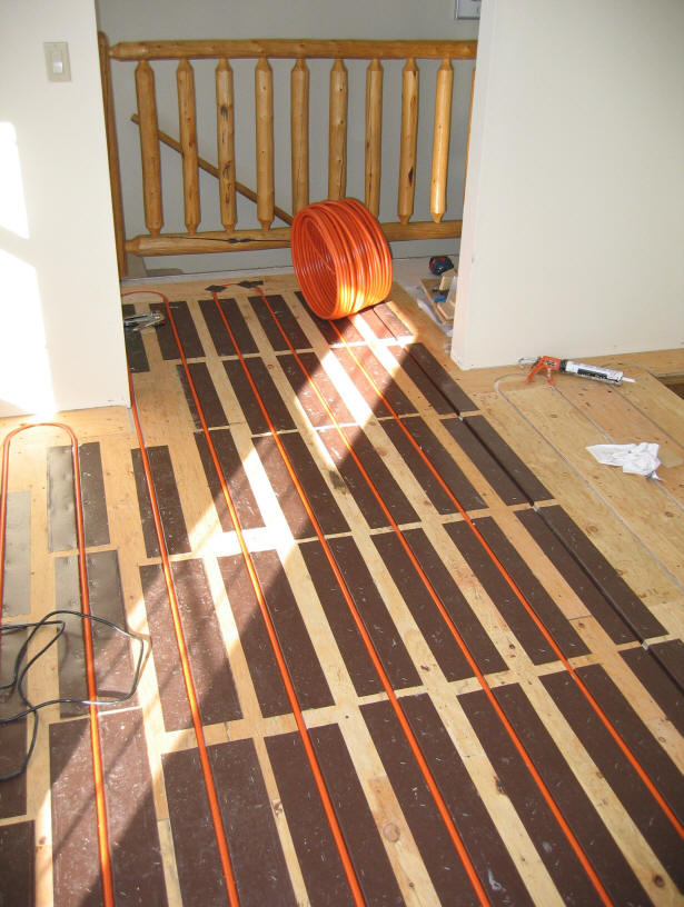
Picture showing floor loops being
installed.
Plywood spacers are used to make a
groove for the PEX pipe. Homemade aluminum sheet heat spreader
plates are used to improve the heat transfer to the room
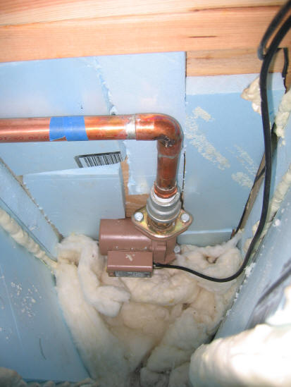
This shows the Taco 008 bronze
circulator pump that circulates water to the collectors mounted to the side of
the tank.
The connection through the tank wall
is just below the pump body.
This connection is made through a
bulkhead fitting.
This is the only plumbing line that
penetrates the tank wall -- the rest of the connections go over the top edge.
The tank sits low enough that the
inside of the pump is always flooded -- the pump is not self priming.
The insulation arrangement is set up
to allow the pump to pick up enough heat from the tank to prevent freezing, but
not so much as to overheat the pump.
The pump is rated for continuous
operation at 200+F, so the insulation arrangement is probably not too critical.
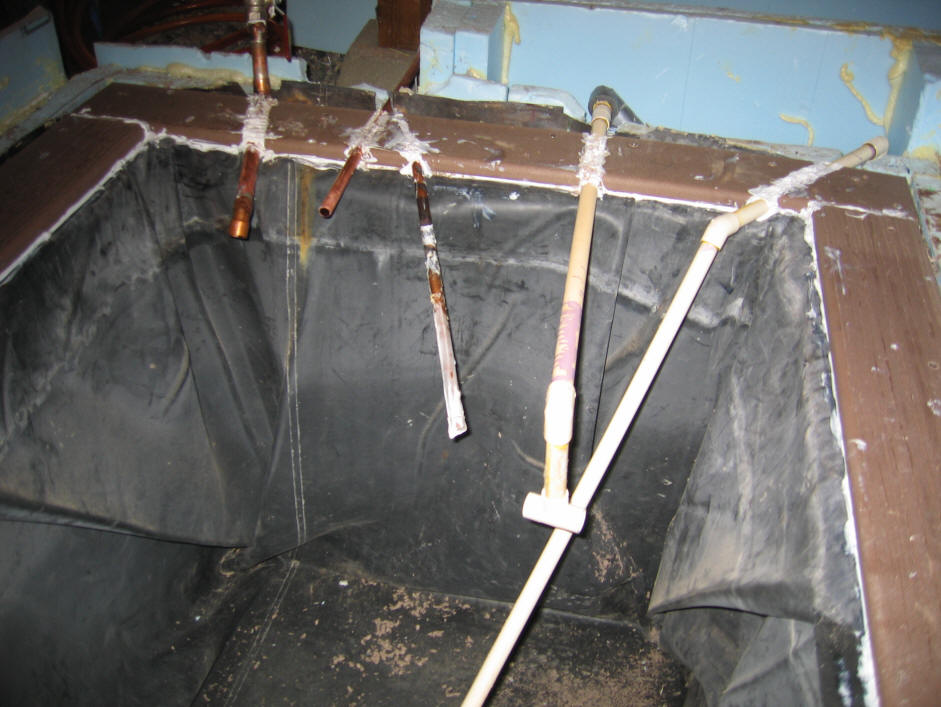
This shows the new arrangement of all
of the plumbing connections to the tank except the pump (see above).
All of the connections come in over
the top of the tank through grooves in the boards that surround the top edge of
the tank.
This allows a lid with no connections
through it, so it can be removed easily.
A little messy, but functional.
The connections from left to right
are:
- Return water from collectors --
must terminate above the tank waterline
- Tank vent line -- just runs over a
bit and up a bit -- allows air to enter or leave the air space above the water.
- The tank temperature sensor lives
inside the angled copper pipe -- its a 10K thermistor.
- CPVC line to the house. The T
on the end of this line is set up about 3 inches under the tank water surface --
it conveys hot water tot he house.
- CPVC line coming in from the
right corner is the water return line from the house -- it continues over the
the lower far end of the tank
The white gunk is silicone caulk to
keep water vapor from escaping the tank.
There is a stainless screen filter
cartridge in the CPVC supply line to the house just beyond where it exits.
At the end of the first season there
was nothing in the filter.
The lid for the tank is lined with
EPDM on the bottom, then a couple layers of rigid foam insulation, topped off by
a layer of OSB.
The lid is clamped down to the tank
with long deck screws at about 1 ft intervals. This connection has proved
to be vapor tight.
Gary Dec 1, 2007