Search
The Renewable Energy site for Do-It-Yourselfers
Solar Shed -- Shed and Collector Wall
Shed and Collectors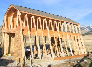
The storage shed is 24 ft by 12 ft,
with the long dimension facing south. The shed is adapted from one
described in "Build a Shed", Taunton Books. It has a gambrel
style roof, which has been modified on the south face to allow a maximum area to
integrate solar collectors (see picture). The south wall of the shed uses
conventional 2X6 24 inch on center framing with OSB sheathing. The collector
frame is mounted directly to this sheathing (the sheathing is the back wall of
the collector). The collector glazing also acts as most of the south
wall siding and roof. This sharing of components reduces material use and
cost for both the shed and the collector.
The collectors are site
constructed, but use an absorber plates that were purchased pre-assembled.
Since this is a drain back system,
the absorber plates must be installed such that they have a drainage slope
toward the storage tank -- this insures that the water in the collectors drains
when the pump is turned off. |
|
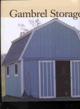
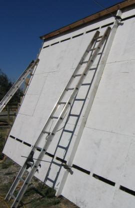
The shed design was adapted from the
one pictured here, which is from a Taunton "Build A Shed" book. Basically,
the steep part of the roof slope on the south side was extended all the way to
the ground so that it forms both the roof and the south wall. This makes
an about 11 ft high surface for integrating solar collectors. The length
of the shed was increased from 16 ft to 24 ft to provide more storage area, and
more collector area.
There are six collectors of 4
ft by 10 ft each. The collectors are integrated with the south wall of the
shed. The collectors are site built, but use pre-assembled
commercial absorber plates.
Click images for full sized pictures
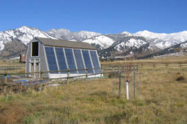
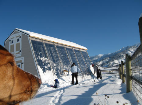
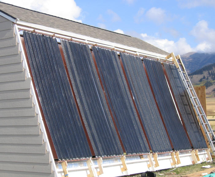
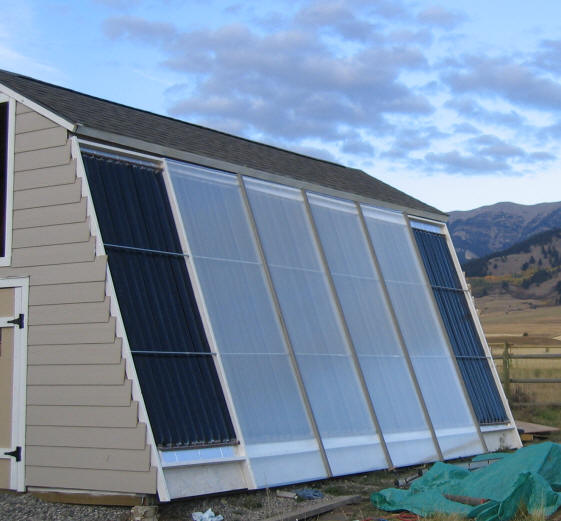
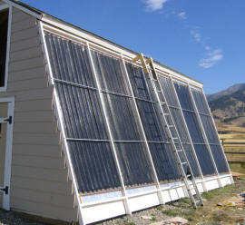
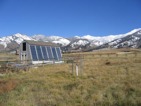
The finished Solar
Shed with 240 sqft of solar water heating collectors in south wall
Collectors -- Make or Buy?
There are several options on how to
make/buy the collectors:
-
You can buy commercial collectors
at $30 per sqft -- good quality, less work, more money.
-
You can make the entire collector
yourself -- lowest cost, most work, more skills, perhaps somewhat less
performance (depending on what scheme you use).
-
You can order completed absorber
plates (the guts), and make the rest -- this is midway in all respects between
the two options above.
I chose the third option of ordering
pre-made absorber plates, and making the framing myself. This offered a
substantial cost saving from commercial collectors, and a substantial labor
saving from making the full collector myself. It also allowed me to better
integrate the collectors with the wall and make maximum use of the wall space
for collectors. The resulting collectors cost about 1/4 what
commercial collectors cost -- a $5500 saving.
This paragraph updated October 31,
2011: I ordered my absorber plates from
SolarEnergy, a company that has since gone out of business. Some of the
makers of solar collectors will sell absorber plates SunEarth would be one place
to try -- the prices don't appear to be as good as when I got my plates.
Another possible source that several people have used is
http://www.sunraysolar.com/index.php
. Other possibilities here --
sources
. If I were doing this project today, I would make the collector absorber
plates as is done in this project...
Cost of Collectors Per Square Foot
| Item |
Cost ($/sqft) |
Notes |
| Absorber Plate |
6.20 |
from solarenergy.com |
| Twin Wall Polycarbonate glazing (1) |
1.50 |
|
| Other Glazing components |
0.40 |
glazing retaining strips |
| Insulation (1 inch) |
0.50 |
one inch polyiso insulation |
| Collector Frame |
0.25 |
2X4 framing |
| Siding credit |
-2.00 |
collector glazing provides siding |
| Total |
$6.85 |
about 1/4 of commercial collectors |
(1) If using polycarbonate glazing,
see the section on collector venting below.
The table does not include shipping charges, which can add up if you can't get
glazing and absorber plates locally.
Shed Construction
The pictures below show a bit of the
construction of the shed.
Since most people will want a
different style shed, I have not included much detail on the shed construction.
The main idea is to provide a large
south wall that is well oriented for solar collection, and to integrate the
collectors with the wall as much as possible.
Click images for full sized pictures
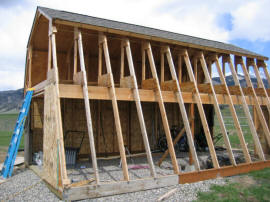
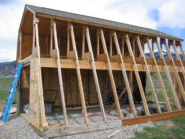
The basic framing of the shed.
It is supported on concrete piers, and uses mostly ordinary stick framing.
The gambrel roof area is constructed with homemade trusses that leave a large,
open storage attic.
The excavated area just that is just
visible inside and to the right is where the thermal storage tank lives.
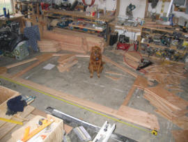
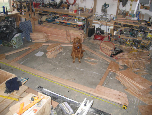
Building the roof trusses for the
shed in the shop. The stacks of precut lumber in the back are for the rest
of the trusses. With some marks on the floor, and everything precut, the
truss building goes surprisingly fast. Each truss is light enough for one
or two people to put in place easily.
One thing to be careful of is
that the stud spacing must line up with the collector frame (described below).
Since most of the twinwall glazing panels want their supports spaced 48 1/4 inch
apart, the stud spacing will probably want to be a bit over 24 inches to so that
the centerline to center line distance over two stud bays is 48 1/4 inch, not 48
inches.
Collector Construction
The next four pictures show how the
collector frame can be laid out on a flat surface to save some time and
increase the chances of things fitting.
The collector frame 1) holds the
absorber plates in position, and 2) supports the glazing panels.
To preview how this frame fits on the
shed collector wall, skip down a few pictures.
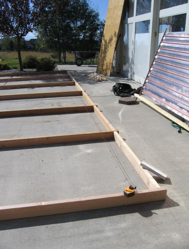
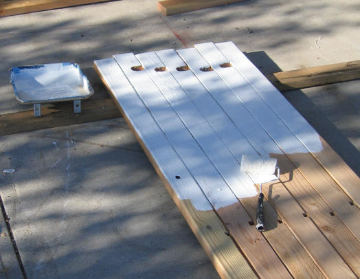
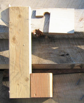
Cutting and prparing the collector
framing:
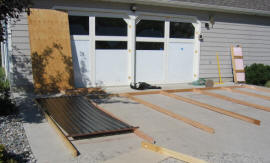
This shows laying out the collector
frame on the driveway to make sure everything fits.
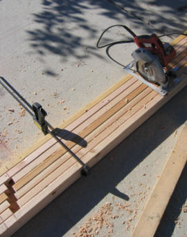
Use a chalk line to layout the
collector dimensions on the driveway (or any flat surface).
Once you have checked that the
dimensions are correct, precut all the pieces of the frame.
Once you have the frame laid out, its
a good idea to trial fit an absorber panel, and a glazing panels.
(note the glazed shop
doors in the background -- these glazed doors heat and light the shop all winter
-- the white filler panels are installed in the summer to reflect some sun and
prevent overheating. A standard overhead garage door behind the glazed
door provides night insulation ...
more)

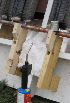
Marking off the line for
notches that the top collector manifold is going to be supported by. For
drain back systems, this must be sloped at least 1/8 inch per foot toward the
supply line end of the manifold -- more is better.
Marking all of them at once in this
saves time, and reduces the chance of errors.
All of the vertical frame
members cab be clamped together to so that the notches for the glazing supports can all be
cut at the same time. This also insures that all the glazing support
notches will line up.
The notches visible at the bottom
support the collector absorber plate lower manifold. Note the down slope
for drainage.
Note! -- no manifold notches in the
end (most east and most west) frames.
The things to accomplish at this
stage:
- Notches to support upper and lower
manifolds.
- Notches for the EMT glazing
supports.
- Holes for the lag screws that hold
these framing members to the collector wall studs. Drill a shallow large
hole to counter sink the lag screw head into, and then a pilot hole all the way
through.

This is also the easiest time to do
the painting.
Installing the collector bay framing:
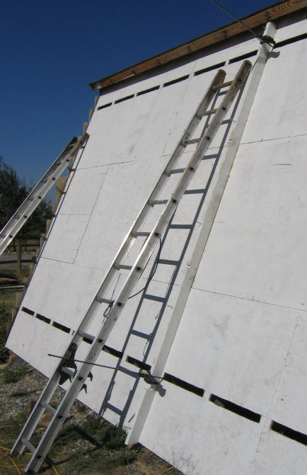
This shows the collector wall with
the OSB sheathing installed and painted.
The first (center) 2X4 for the
collector frame is being positioned. Do this one VERY carefully.
In mounting this first vertical, make
sure the following conditions are satisfied:
-
That it lies over one of the wall
studs, so that it can be anchored into it.
-
That it is plumb.
-
That the bay spacing to the left
and the right works out correctly.
-
That it runs straight from top to
bottom.
The vertical 2X4's at the edge of
each collector must be correct if the glazing panels are to fit, and this first,
center frame is the one that sets up all the rest. So, make sure its right.
Attach the center vertical frame to
the underlying wall stud with 6 inch lag screws, using the holes that you
pre-drilled earlier. Make sure the heads of the lag screws do not stick
out above the face of the 2X4 that the glazing is going to be mounted to.
The open horizontal slots in the OSB
are for a venting system to prevent collector overheating when the collector is
stagnated -- see Collector Venting below.
This shows the collector frames being
built on the OSB sheathing. Each 4 ft collector bay has a vertical 2X4 on
each side, and horizontal 2X4's at the top and bottom.
Once the center 2X4 in in, the 2X4's
at the top and bottom of the adjacent bays can be installed -- these will
precisely set the spacing to the next vertical 2X4. For the 48 inch wide
twinwall glazing that I used, the center to center spacing of the verticals is
48 and 1/4 inch -- the panels are 48 inches wide, and the 1/4 space allows for
some expansion.
To insure that the vertical 2X4's do
not wander off plumb, use a scrap spacer 2X4 that is cut to the bay width to
check the spacing at several points -- that's what the unpainted 2X4 in the
picture above is being used for. All this precision is to make sure the glazing
panels fit properly.
Its a good idea to have one of the
glazing panels handy to check that the spacing of each bay is correct as you go.
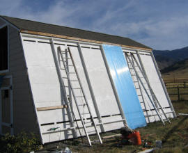
Installing Insulation Panels:
This shows the polyisocyanurate
insulation board being installed in the collector bays. This insulation
reduces heat loss out the back of the collectors.
The panels are one inch thick, and cut nicely
with a razor blade knife.
Be sure to use the polyisocyanurate
insulation, as the polystyrene (pink, blue and white stuff) will NOT hold
up to the temperatures (trust me on this).
Most lumber yards carry the polyiso,
but may not know it by that name. It is usually light brown in color, and
has face sheets of alum foil or fiberglass.
Installing the collector absorber
plates:
The absorber sheets
positioned for soldering by temporary scrap wood supports. They are
supported about 4 inches out from the collector frame by the temporary supports.
Once all the panels were soldered together, they were just slid back as a unit
into the notches on in the 2X4 collector frame.
This was a method I used to avoid
putting unions in between each absorber plate. I think that if I were
doing it again, I would probably use the unions. The negative side of the
unions is they are a bit spendy, and I have seen many reports of leaks at
unions. The plus side is that they allow easier assembly, and allow easier
replacement of an absorber at some (hopefully) very distant time.

These are the scrap wood jigs I used
to position the panels for soldering.
The notch in the small one (upper
left) just fit over the upper manifold, and held it out about 5 inches.
The left one supported the lower
manifold about 4 inches out.
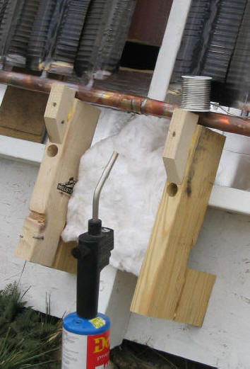
This shows soldering one of the
manifold connections using an ordinary 1 inch copper pipe coupling.
Once they are all soldered, the whole
6 panel assembly is pushed back into the supporting notches in the 2X4 collector
frame.
See the "Lessons" section for a
potentially better way to do this.
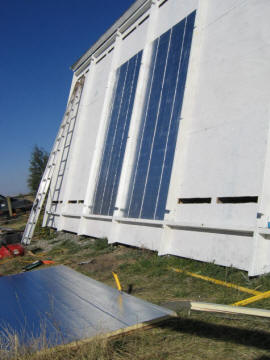
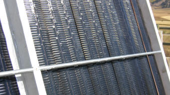
Shows the absorbers in their final
position. Note the 4 inch down slope from the west side to the east side
for drainage. The horizontal metal members that are 1/3 and 2/3rds of the
way up the collector are supports for the glazing to eliminate buckling of the
twinwall glazing as it warms up. They are made from EMT electrical conduit, with a
bead of silicone caulk between the twinwall and the EMT.
Update:
I would recommend positioning the upper EMT glazing panel support closer to the top -- the panel tends to
deflect more at the top, so this is where the support is best positioned.
Picture of the EMT conduit glazing
supports. I used a bead of silicone caulk to keep the glazing from
directly contacting the galvanized surface of the EMT.
These EMT "supports" do not really do
any supporting of the glazing, they just keep the glazing panels from buckling
as they warm up. EMT is cheap, straight, and galvanized, so it should last
well.
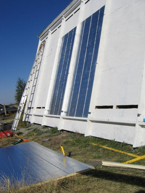
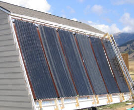
Glazing:

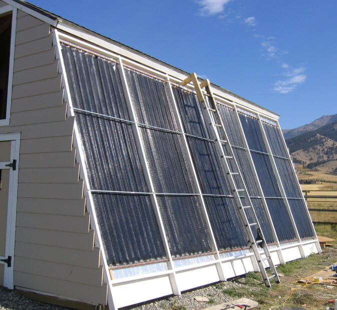
Showing four of the 6 twinwall
polycarbonate glazing panels installed, with two to go. The glazing panels
are secured in place with 1X2 members and stainless steel screws. There is
no caulk, glazing tape, or gasket between the polycarbonate and the 2X4 edges
of the collector frames.
The panels are simply pushed against
the 2X4's with the 1X2's battens. So far, this seems to be working fine, and keeps
the water out. This arrangement (it is claimed) allows the PC panels
to expand more easily -- I'm not so sure about this, but one advantage it does
definitely have is that its very easy to remove the glazing panels if (for
example), you missed a solder joint inside the collector :)
For the vertical 1X2 ish battens that
hold the glazing in place, I tried one of the plastic deck woods. Ordinary
wood can be used for this, but a number of sources have said that it does not
hold up well with the constant exposure. My logic is that the plastic deck
woods are supposed to last more or less forever in deck applications, and so may
have a good life for this application. There are also a number of
commercial choices of twinwall panel edge hold downs -- your glazing supplier
will no doubt have some.
A drain hole is provided at the
bottom of each collector bay to drain any water that happens to get in.
Except for the leak caused by my bad solder joint, I have not seen any water get in, and we have
had a couple good rains.
Note that after this picture was
taken I extended the roof edge about 5 inches to prevent any tendency for wind
driven rain water to get into the collector boxes. I plan to add a gutter
so the collectors don't get runoff from the roof. Update: the gutter
should definitely be included, in that when snow accumulates on the roof, and
then melts, it tends to drop onto the glazing panels bringing some dirt with it.
The other option would be to make the collectors vertical, which I have come to
think is a better all-around arrangement.
Finished collector
Collector Venting
I was a bit concerned about the
glazing becoming overheated when the collector is stagnated (no fluid being
pumped through it). I decided to include air vents in the back wall of the
collector that would allow cool air from inside the shed to enter the collector
near be bottom through a lower vent, and heated air to exit the collector near
the top. This effectively makes a thermosyphon air collector, and should
keep the stagnation temperatures down. This paper discusses a somewhat
similar approach:
http://www.builditsolar.com/Experimental/44-31-%20Harrison1Stagnation-temp-control.pdf.
I am working on some type of thermally actuated gadget to close the open the
vents automatically when the temperature exceeds (say) 190F.
These vents should be screened to
keep the critters out. There should be a small airflow passage on the back
side of the absorber plate, so that any dust in the air does not settle on the
sun side of the fins.
It appears that these vents (or some
equivalent form of cooling) are required for the stagnation condition.
This chart shows the temperature of
the inside surface of the glazing near the top of the collector.
This is around solar noon.
Initially all the collector vents are closed.
At minute 1, the circulation pump is
turned off, and the collector temperature starts to rise. It continued to
rise until it leveled off at about 205F around minute 8. At this time, the
temperature of back near the absorber surface is a bit over 300F.
I opened the vents at minute 9, and
the glazing and collector temperature immediately begin to drop, and eventually
reach a very nice 110F.
This was done under sunny conditions,
Tambient about 60F, and windy.
In a later test the next day, with
Tambient at about 25F, the collector reached even higher temperatures, and the
glazing near the top of the collector had a noticeable inward deflection from
the expansion. This did not look good to me for the long term health of
the polycarbonate panels. The polycarbonate glazing is listed as having a
temperature capability of 270F, and I don't believe that this was exceeded, but
I don't think it would be good to routinely expose the panels to these
relatively high temperatures.
While I plan to do some more testing,
my tentative conclusion is that this collector when glazed with twinwall
polycarbonate needs some form of cooling when stagnated under sunny conditions.
One thing to be alert to is that this
high internal temperature condition develops very quickly when stagnation occurs
under sunny conditions.
The following are possibilities to
resolve this overheating issue:
-
Use a venting system similar to the
one I have incorporated on my collectors.
-
Use single wall poycarbonate
glazing (e.g. SunTuf corrugated glazing, or Dynaglass). I think that
better heat transfer through the single layer would take the glazing
temperature down. Be sure to include adequate horizontal glazing
supports to control the buckling of the panel as it warms up.
-
Use an absorber that does not have
a selective coating on it. This would reduce the collector temperatures
-- I'm not sure if this change along would be enough to eliminate the need for
venting, but it might be.
-
Use glass -- this would not reduce
the temperature, but the glass will withstand the higher temperature better.
This just adds a lot of cost and labor.
-
Make the collectors vertical.
This reduces the solar radiation on the panel during the summer, early fall,
and late spring. This is just because the sun in higher in the summer
sky. It also makes it easier to incorporate an overhang above the
collectors that shades all or part of the collectors in the summer.
Some other things that I plan to do
on my collectors that I think will improve the situation (but probably not
eliminate the need for ventilation at stagnation):
-
Use 3 of the horizontal glazing
supports instead of 2 to control and tendency toward thermal buckling, and
make sure that one of them is near the top of the collector (which runs the
hottest).
-
Increase the distance from the
glazing to the absorber plate. Using 2X6's for the collector frame would
allow for more glazing to absorber space, and also allow the use of 1.5 inch
polyiso insulation on the collector back.
I believe that the combination of
making the collectors vertical and somewhat deeper (use 2X6 framing) will
eliminate any serious tendency for overheating. Its still not a bad idea
from a glazing life point of view to keep the collectors from cooking all summer
-- this might include: 1) seasonally used vents as described above, 2) an
overhang that shades part of the collector from the high summer, or 3) a shade
cloth covering.
I am still looking for a good way to
automatically open a cover on the upper vent when the temperature in the
collector exceeds (say) 200F, and close when it goes below this. Any
ideas?
Update: 1/15/07
Vertical Collectors:
My thinking in using collectors
tilted at 70 degrees was that this is a good angle for winter collection, and
that it looked better with the shed (basically its just an extension of the
gambrel roof slope to the ground). While the 70 degree tilt is not a bad
scheme, I have come to think that a vertical collector would be an all-around
better choice for these reasons:
-
The collector would not be
subjected to rain or melting snow dripping off the roof. And, it would
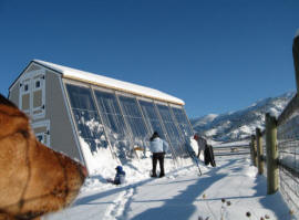
be less likely to have any accumulation of snow on it after a snow storm
(although snow accumulation on the collector is an infrequent occurrence
with the 70 degree tilt, it does happen once in a while -- as indicated by the
picture above).
-
The vertical collector would be
less subject to overheating in the summer. The summer radiation levels
on a vertical collector are substantially lower than a tilted collector due to
the high summer sun.
-
It is possible to include an
overhang above a vertical collector that shades a portion of the collector
during the summer, early fall, and late spring. This further reduces any
overheating tendency.
-
The low winter sun works well for
vertical collectors. They collect nearly as much heat as tilted
collector. If there is a reflective surface in front of the collector
(like a snow field), a vertical collector will collect even more solar
radiation than a tilted collector.
-
Its probably a bit easier to build
a vertical collector/wall, and easier to further integrate the collector
bays right into the wall.
All of this said, if you have a
reason that you prefer tilted collector, it will work just fine.
Collector Construction:
A few things I might do differently
on the construction:
-
I would increase the number of
horizontal glazing supports to 3 instead of 2, and make certain that the top
one was within 2 feet of the top of the collectors. Again, these can be
very light weight supports -- there only function is to keep the glazing
panels from thermal buckling as panels heat up.
-
I would make the collector box 5.5
inches deep (i.e. use a 2X6) instead of 3.5 inches deep. I would use the
extra thickness to 1) go to 2.0 inch thick polyiso back insulation (about R
12), and 2) to increase the spacing between the glazing and absorber plate,
which would make the glazing surface run a little cooler and also eliminate
any chance that the glazing would deflect inward and touch the hot absorber
plate.
-
I would use unions between each of
the collector bays. I think that overall the extra cost of the unions
would be worth it for the labor saved on the installation, and allowing for
easier repair or replacement of a collector panel.
Note: I have been told that silicone rubber hose can be used to join the
absorber plates together for non-pressurized (e.g. drain back) systems.
The silicone rubber should be protected from long term sun exposure with heavy
aluminum foil. You would also have to make sure that no weight rests on
the hose connections -- that is, the manifold would need to be supported by
some form of bracket.
Gary Updated 10/25/06
Updated 10/31/06, 1/15/07