Neil will answer questions about the
system here njb-designs AT talk21 DOT com Replace the AT with
an @ and the DOT with a period.
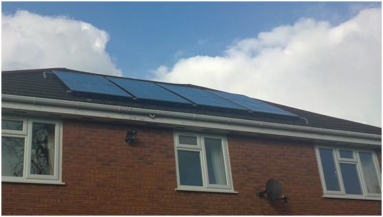
Clearly, this is a very nicely and
skillfully done system, but I'll offer a couple comments/suggestions anyway :)
Two Pumps -- Neil had to
use two pumps to achieve the pressure head that is needed at startup in
drain back systems to pump water from the storage tank all the way up to the
top of the collector. But, once flow is established, one of the two
pumps would be sufficient to maintain flow. Some people have handled
this by using two pumps at startup with the 2nd pump on a time delay relay
that shuts the pump off after a short time interval. This cuts the
pumping power in half, but does add a little complexity.
Neil reports that he has experimented with this and was not happy with the
flow pattern from a single pump, so this solution may not work in all cases.
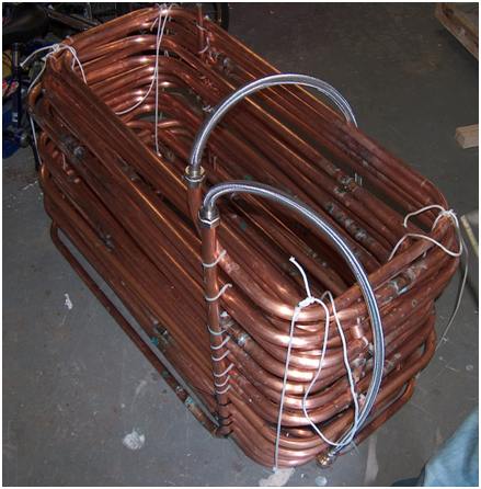
Silicone or Epoxy -- Neil
suggests that a thermally conductive epoxy might be a better choice for
bonding the copper tubes to the aluminum fins. This may be true, but
for all the reasons
stated here, I still like silicone. If the lower thermal
conductivity is a concern, there are thermally conductive silicone caulks
made. I plan to test one of these this summer, but for the
reasons stated at the link just above, I don't think it will make much
difference.
Epoxy might work even better than silicone, but I think there is a little
risk involved in using it until someone tries it for a couple years.
The lack of flexibility and the lower temperature limits are the areas that
bother me a little.
If you have some experience with
this, please let me know.
Placement of Tank Temperature
Sensor -- Neil found that with the temperature sensor for the
differential controller placed at the bottom of the tank that when the tank
was temperature stratified and under moderate sun conditions, he could have
a situation where cooler water was drawn from the bottom of the tank, sent
through the collectors, and come back warmed up some, but cooler than the
water in the top of the tank. To avoid this, he moved the sensor to
the top of the tank.
To me, this is a tradeoff. If you draw cool water from the bottom of
the tank and it comes back warmed up some, but not as hot as the water in
the top of the tank, you are still adding heat to the tank, but you are
degrading the temperature stratification in the tank. So, if more
stored heat is the objective, I'd leave the sensor at the bottom of the
tank, but if more temperature stratification is the objective, then you
could try moving the sensor up in the tank.
Neil might give us more on this
once his logging system is up and running.