Search
The Renewable Energy site for Do-It-Yourselfers
Woodsy's $1K Solar
Water Heating System
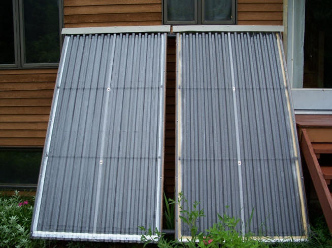
Woodsy's Solar collector
construction and installation details:
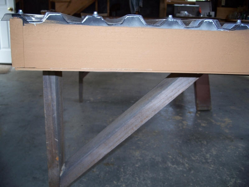
The collector frames are made with full 1" X 4" band sawn pine stained with
solid color latex stain matching the house. Exterior dimensions are 48 1/2" X
97". I shortened the length 1" to allow a good drip edge on the bottom --
1/2" would be plenty.
Note: the end sections of frames are 3 1/2" in width to better accommodate the
corrugated polycarbonate glazing. (picture)
After applying the 3/4 wide weather stripping to the top sides and the foam
closure strips on the ends, its ready to drill and fasten.
Click on pictures for
full size
The Frame back is 3/16" hardboard centered and screwed to the bottom of frame
and 1 3/8" foil faced polyisocyanurate board insulation is cut to fit inside the
frame making a rigid base for the absorber plates. The hardboard is heavy (30
lbs.) but cheap, i would try to find something lighter next time, maybe metal
roofing material.
The type M copper pipe grids are all
1/2" including manifolds. I took a gamble going with the 1/2" manifolds because
it is a small system and it seems to be working well, experimental and somewhat
cheaper nonetheless. Two inch holes were drilled in the side frames to
accommodate the 1/2" pipe and 2" foam insulation.
Click on picture for full size
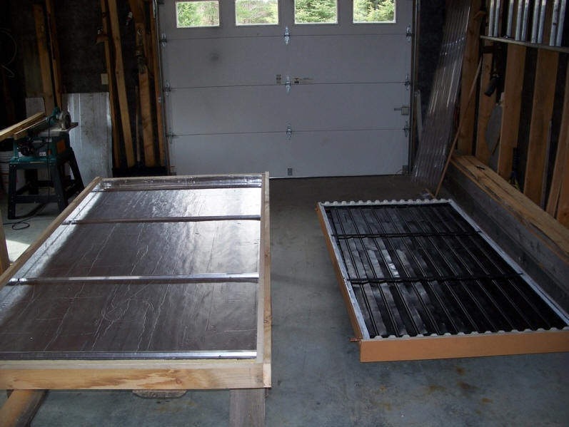
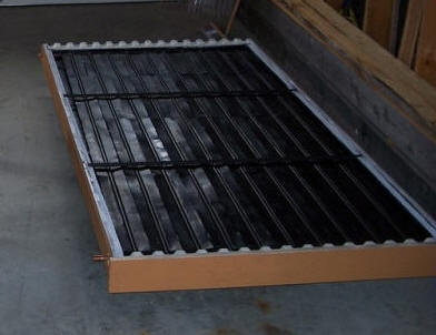
The ten risers in each collector are spaced approx. 4 1/2" apart and the grid
with aluminum fins attached to the undersides of piping sits on 4 aluminum angle
pieces fixed to the insulation . The grid is tilted clockwise in the frame
for good drainage. The grids are then wired on the 4 corners through to the
hardboard to hold them in place making for a semi-floating grid. I wanted
a little play when it came time to couple the 2 collectors together.
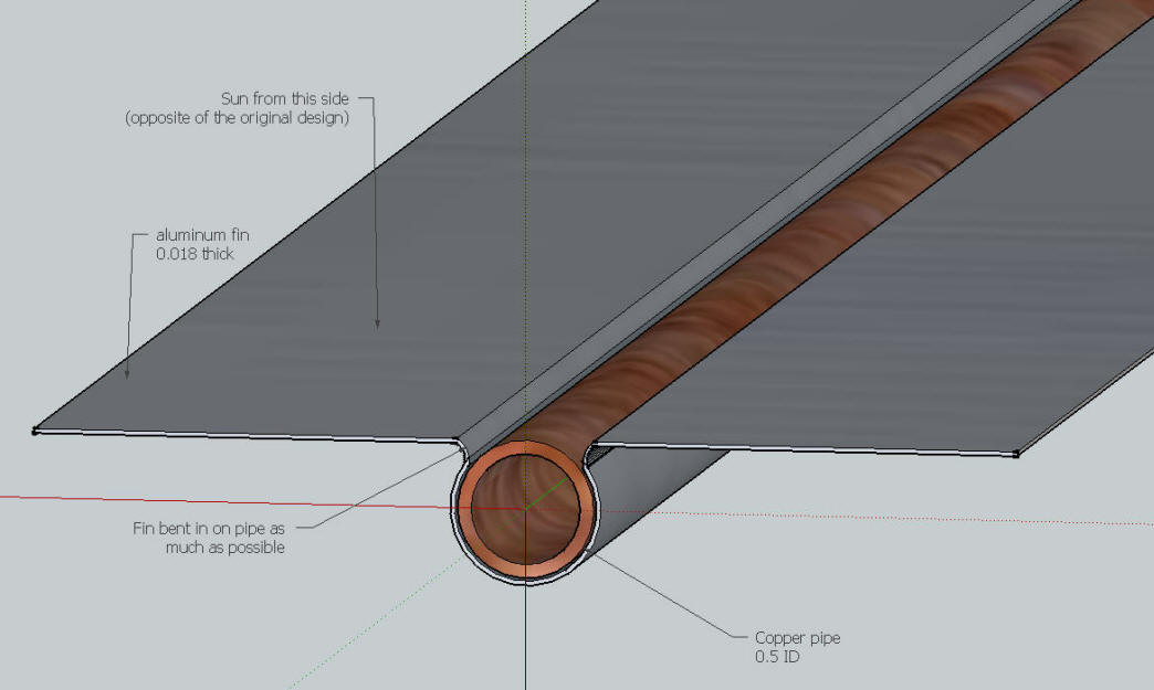
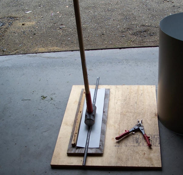
The .018 thick painted aluminum fins were started by cutting 5 1/4 " X 2' strips
from a 2' X 50' pre-painted coil of flat stock aluminum. I used Gary's fin forming method
but added a stop strip on the side of the mold in order to center the fin over
the mold. Molded the aluminum with the bottom of sledge, beating it down
in the 5/8" wide slot with a 5/8 inch iron rod. I then pulled the rod out
and continued the bend just enough so that it would clamp the pipe securely,
then bent the sides of the fins back to flat. This takes some hand work. This
method, for whatever it is worth, leaves a portion of the copper pipes exposed
to the sun. This method of attaching fins is experimental also, but after
6 weeks in use, they seem to be clamping the pipes well.
Click to enlarge
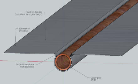
Detail of fin and tube -- note that sun
shines on upper surface.
Click on pictures for
full size
With the fins attached and grids fastened to the boxes, a coat of flat black
high heat spray paint was applied. Two horizontal copper pipes in each collector
(extra) support the center portion of the glazing.
Next, the
polycarbonate glazing is fastened to the frame and a 1" x 5" board (a little
overhang is good on the sides) is screwed to the top of frame sealing the
glazing from rain/snow. I went the extra step and used some of the
remaining aluminum and formed a metal cap over the 1 X 5 on top of collectors.
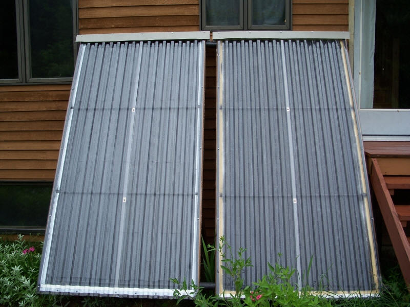
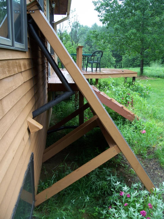
Mounting the collectors on the south wall was a little tricky (it took two
people for this) getting them lined up just right to couple them together with
unions. Brackets and long wood screws hold the collectors to the wall on
top and angled 2x4 braces attached to the collectors and sill plates of the
house hold the bottoms, using long screws.
Click on pictures for
full size
The water is supplied to the collectors with 3/4" copper from the bottom right
side and exits the top left backside (window opens out on that side) with 3/4"
copper.
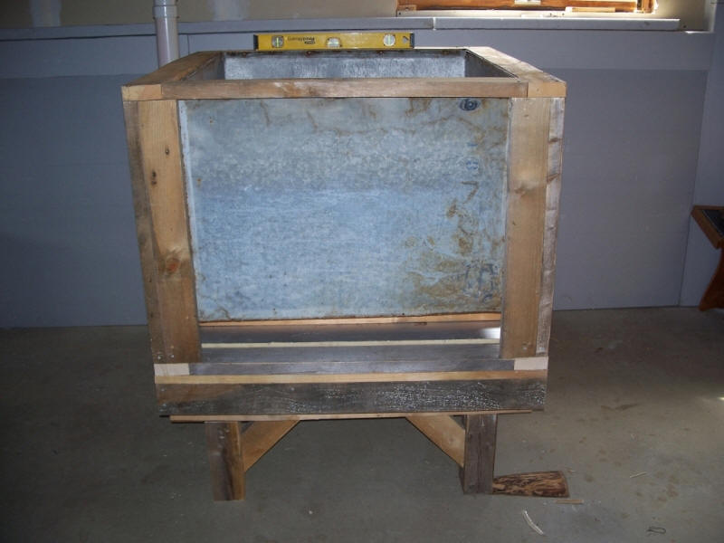
Drainback/Heat exchanger tank and
interior plumbing details:
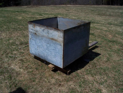
The 18 gauge galvanized metal tank
was salvaged from an old farm dump in woods behind the house I had to cut a
couple trees down in the grown over dump in order to twitch it out w/tractor.
The wood frame and base needed to be rebuilt due to rot and the drain elbow need
to be TIG welded to repair a crack in it.
A stand made of 4X4s was attached to the underside of tank base to reduce head
height thereby reducing pump size and cost. Head height is about 7 1/2
feet.
Click on pictures for
full size
The 2x4s, 4x4s, and boards for this project and frames for the collectors are
from the property as well.
Click on pictures for
full size
The tank bottom has 1" of foil faced polyisocyanurate board insulation, the
sides have R-11 fiberglass insulation which I had on hand. The sides were then
covered with black plastic making a tight seal. The top lid has 2 layers
of 1 3/8" foil faced Polyiso board insulation for about R-20. It seems to
retain heat well. The bottom layer of the lid has two 1' long X 1 1/2" cutouts
for the PEX-B tubing entering and exiting the tank.
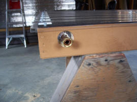
The tank with heat exchanger in it when
full holds 130- 140 gals water. I installed a shutoff valve and hose bibb
at the outlet of tank.
The heat exchanger is 1" X 300' of PEX-B radiant (certified potable) temperature
rated to 180 degrees. Inside Dia. is 7/8" and will hold approx. 9 gals of water.
Tubing comes from Blue Ridge Co. for $170.00.
The pipe coil sits on 3 concrete blocks in the drainback tank and the layers of
tubing are separated with 1/2" plastic hot water piping cut to 10"lengths.
I used galv. fence wire that i had on hand to hold it all down to the blocks.
This stuff will float even with water in it if not tied down.
The circulator pump is a Bronze Taco 006 3/4 " with sweat fittings. It is
pumping about 3 GPM. It is a very quiet pump that draws 60 watts. I
went with the sweat version because it is a replaceable cartridge type pump.
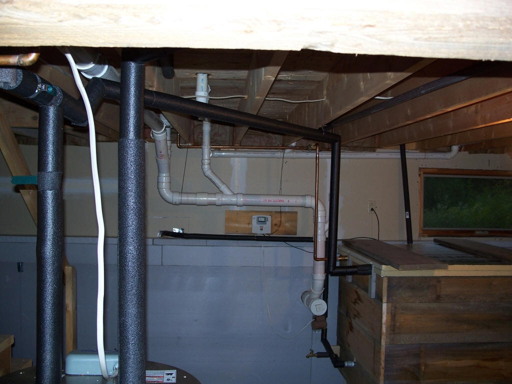
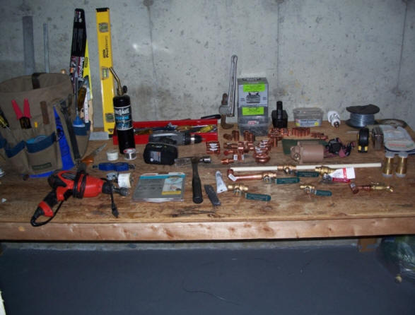
The interior plumbing was fairly extensive as this picture of the fittings laid
out on the bench shows.
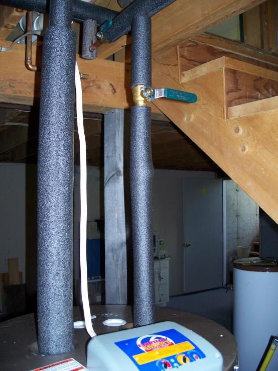
A new 40 gal electric water heater needed to be installed replacing a 18 yr old
one.
The new water heater is well insulated w/3" foam and has a controller on top
with 4 different settings and
easy temp adjustment with turn of a dial fro 80* to 150*.
Click
on pictures for full size
|

Shown in bypass mode. |
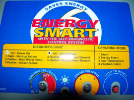
Backup water heater with various
energy saving modes.
This is a
Whirlpool Smart Energy model. |
I picked up the water supply to feed the heat exchange coil and new water heater
almost directly over the drainback tank
at the end of cold supply to bathroom and installed a 3/4" ball type shutoff
valve here. In the event problems arise with the new system or new plumbing,
this valve will allow us continued cold water to all house fixtures.
I used brass Watts connectors to join the 1" PEX tubing to the 3/4" copper at
the heat exchange coil, these worked slick .
From the coil to the new water heater was a straight overhead shot with some
fancy angles incl. a couple 45s. Decided to add a couple valves at the new
electric water heater allowing me to bypass it completely when solar water is
hot enough or let preheated water flow into it.
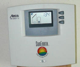
The Steca differential controller makes for automatic operation, when the temp
in the collectors reach 16 deg. higher than water temp in the heat exchange tank
it flips on and will run until collectors and tank water are within 6 degrees or
140 deg. I like it. The display on the controller shows tank water
temp or collector temp.
An interesting observation on the last sunny day we had was that the collectors
were running cooler at high noon than say 10 AM or 2 PM due to the high angle of
the sun on the 60 degree angle of the collectors.
The total cost of materials for the system was $1200.
I am very Happy with this system
I am thinking about adding a third
collector at some point to beef the system up and also considering running a
line from the heat exchange tank to a copper coil on the wood stove and back for
winter backup.
Woodsy June 2009
If you have questions, Woodsy can be
found on the
www.HomesteadingToday.com forum in the Alternate Energy group, which is
quite good.
New -- One year
update from Woodsy:
We have had absolutely no problems with the 1K DIY system running automatically.
Our electricity usage dropped 2,665 KWH over a period of 12 months for
total savings of $399.00.
That was better than expected considering last summer was one of the
wettest summers on record here in the Northeast.
The electric water heater has been shut off when the heat exchange
tank reaches 110 deg. and off for as long as 10 consecutive days so
far.
Woodsy
June, 2010
The most interesting variation that
Woodsy included in his design is attachment of the aluminum fins to the copper
tubing, and flipping the fin and tube assembly over so that a part of the copper
tube is exposed to the sun. I'm not sure what the effect on performance of
this change is. It would be nice to do a small panel test on this
arrangement and see how it compares to the
base design.
In any case, I think its a good idea
to use pre-painted aluminum (as Woodsy did), or prime the aluminum and copper where they come into contact
with a corrosion resistant primer to avoid galvanic
corrosion.
The backup water heater with its
multiple energy saving modes might also offer some advantages in operating with
the solar water heater?
Also like the idea of salvaging a
tank if you can find one.
Thanks again to Woodsy for sending in
this material.
Gary June 30, 2009