Search
The Renewable Energy site for Do-It-Yourselfers
Tom's Wind Turbine
-- Turbine Mount, Blades, and Housing
Generator Mount Assembly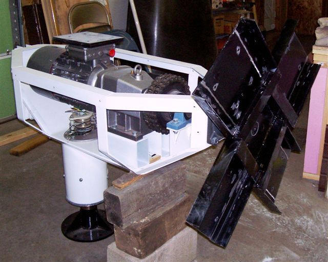
This wind turbine is basically built from the Prairie Turbines design (
http://www.prairieturbines.com/ ). Their assembly manual is pretty
good, better than most I have researched or purchased. I have incorporated
many ideas of my own, but the project could not have proceeded without their
help and resources. Their web site has a lot of good information and
pictures.
This generator is designed for grid-tie applications only. It generates
up to 5.5 KWs of A.C. power, unlike most smaller units used today that
generate varying levels of D.C. power. D.C systems are nice, but require
batteries and/or inverters. The Prairie Turbune design fit the application
I was looking for.
The original design of the Prairie Turbines "Breezy 5.5" generator
housing is rather simplistic and functional, but not what I considered
aesthetically pleasing. I wanted a wind generator that "looked commercial"
but was a product of my own work. We redesigned the generator mount into an
octagon, rather than rectangular, unit with the front and back ends of the
unit tapering down in a more aerodynamic fashion. Having some fiberglass
experience, I knew I could make an enclosure that would match the framework.
Most of the work on the mount was based off the Prairie Turbines assembly
manual, with small adaptations to fit our change to the octagon design. The
generator motor, brass slip ring, torque clutch and prop shaft bearings were
purchased from them. We machined the drive shaft and hub parts. We also
built our own yaw bearing out of some excess stock truck transmission
bearings, some various sizes of pipe, and a good machinist.
Click on pictures for full size
|

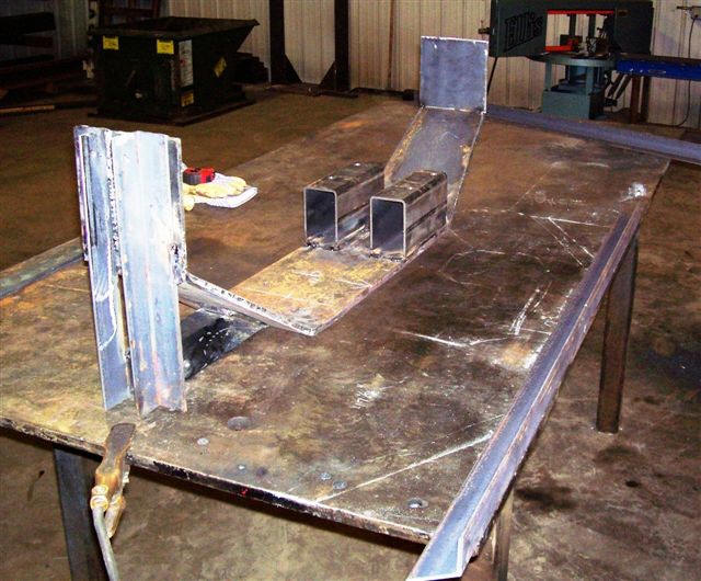
1/2 inch plate base with tail receiver |
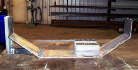
Base with 4" X 6" motor mount risers |
|
Aligning bearing to Generator |
A look at the "receiver" for the tail assembly |
|
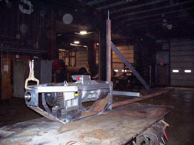
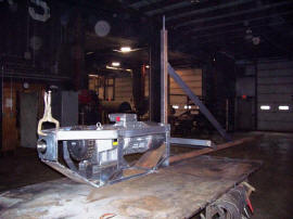
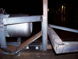
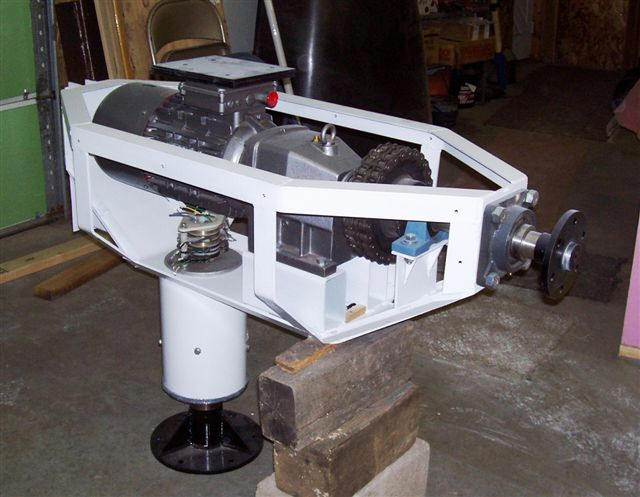
Generator mount complete with blade hub |
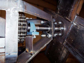
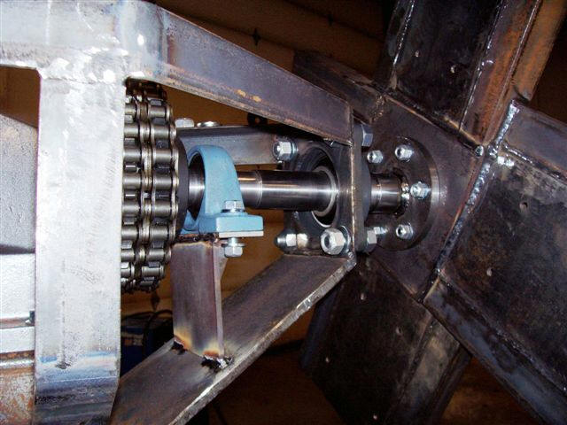
A closer look at the prop shaft bearings |
Turbine assembly showing the 3 phase industrial motor/generator, gearbox,
bearing,
and slip rings.
Carving the Blades
The very first project I completed at
home was the rough cutting of the blades. They are formed from 12' lengths of 2
x 10's. A good hand planer is required for this phase. The book clearly
describes how to build the blades. Once they were roughed into shape, the ends
were painted to seal for cracking. They were stacked on the floor (on skids) and
heavy weights were installed on them to keep them straight as they continued to
dry. The boards used are longer than needed, but help by giving you the ability
to trim cracking of the ends after drying is complete.
Final blade finishing was done many months later, after much of the rest of the
project was completed. The
Prairie
Turbine Book provides for a procedure to deal with any
cracking, and I had one blade needing work. I sanded out a trough and installed
several layers of fiberglass on each side of the blade to strengthen and close
the crack. All final sanding was completed and the blades were ready for initial
balancing (a final balancing is done after painting).
I pre-weighed the hub and the blades,
using this information to match the heaviest blade to the lightest side of the
hub. The blades were all fitted to the hub, and the hub was suspended from a
hoist for the balancing. Each blade had a support beneath it about 6" below the
static level point. Lead was set on the lightest (highest hanging) blades until
I was close to the balance point. I drilled large holes in the blade and melted
lead and poured it into the blades. Two blades were worked several times with
the lead until I got to the balance point, leaving those blades just a tad light
to compensate for the final fill at the lead inserts. A fiberglass patch was
placed on each blade over the weights and body filler was added for the final
finish.
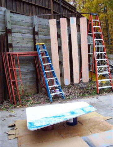
Click on pictures for full size.
|
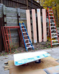
Blanks for the blades in
background, with the tail
in the foreground. |
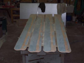
The carved blades. |
At this time it made sense to cut out the tail vane (3/4" plywood), as I wanted
to paint all the "wood components" at the same time. I sanded it for paint (my
plywood was in the form of an old unused sign that was in excellent shape). The
blades were hung from a bar and the tail on a couple 5 gallon pails. They were
painted outside with a HVLP spray gun. I was not happy with the painting results
on the blades; some runs and not as smooth as desired. Painting the tail outside
presented challenges too; bugs. Everything was moved into the garage, sanded
again (180 grit) and repainted. The results the second time with a more
controlled environment were excellent.
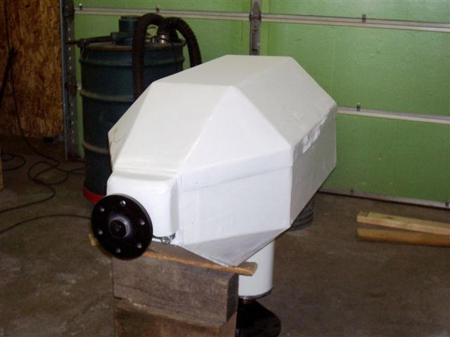
Generator Cover
Once the actual generator mount was
completed, I took the mount, generator, and all the small parts home for final
assembly. The first project was to cut and form 1/4" Luan scraps I had to fit
the various sides of the mount. I had a "two part" super glue that I used to
attach the "mold" pieces to the mount. Once the unit was totally covered, I
taped the entire surface with clear packaging tape as a release agent for the
fiberglass after it cured. I laid up multiple layers (4) for the two side
covers. When they were done, I laid up the top cover with 5 layers for a little
more strength because this cover spans across the top of the generator
unsupported.
Turbine assembly ready for cover.
A 3" x 8" hole was cut into the bottom of the mount, between the two motor
supports, for a ventilation "intake". A mold was made out of Styrofoam for the
outlet and this was attached once completed. Both ventilation openings were
covered with mesh to avoid animal or larger insects getting into the enclosure.
Another mold was made of Styrofoam for a "front bearing cover" to protect the
bearing from the elements. Pictures are enclosed of some of the molds, but
unfortunately I didn't get any pictures taken during the actual fiberglass
process. The covers were primed and painted white, as fiberglass should be
painted a light color to protect the composite material from excessive solar
heat.
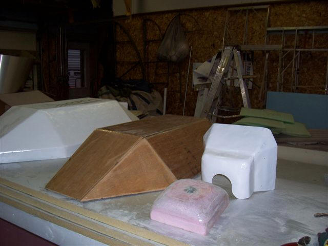
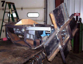
Molds for making the turbine housing.
|
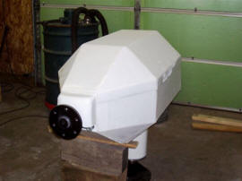
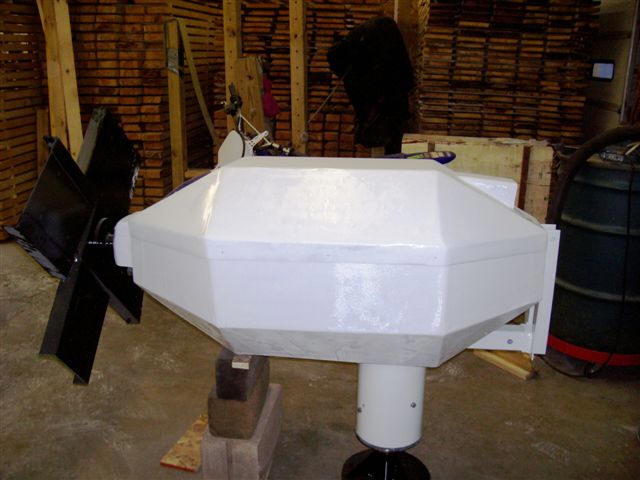
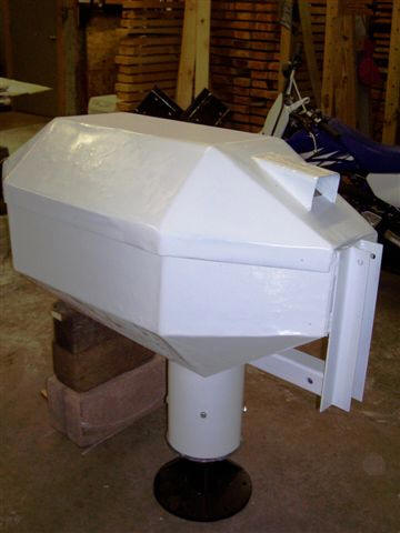
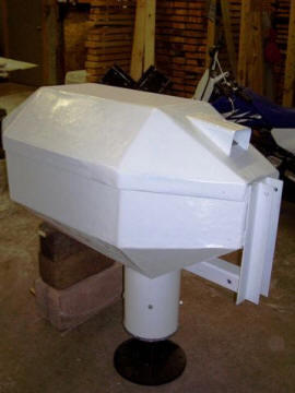
Fiberglass cover from front,
side, and back. |
 |
 |
When the covers were
completed, they were installed with
Clecos to fit, and then the frame was
drilled and tapped for 1/4" bolts to secure the covers. We discovered that some
additional light angle and strap needed to be welded along the main frame to
secure the covers. I also had to do a "release" to fill in an area at the rear
that would require sealing. This was done with a micro/flox filler mixed with epoxy. If I was
to build another unit, I would provide for a gap for the cover to extend below
the rear edge of the mount. We attached the tail mount right to the top of the
main mount, and this was not the best design for sealing.
While sandblasting the tower, I also sand blasted the "Gen Mount", related small
steel parts and the steel tail assembly. The "Gen Mount" was primed and painted
white, while the rest of the parts were painted black. The motor was dropped
into the mount and all the parts were installed for the drive. Other than
wiring, the unit is ready to be installed on the tower.
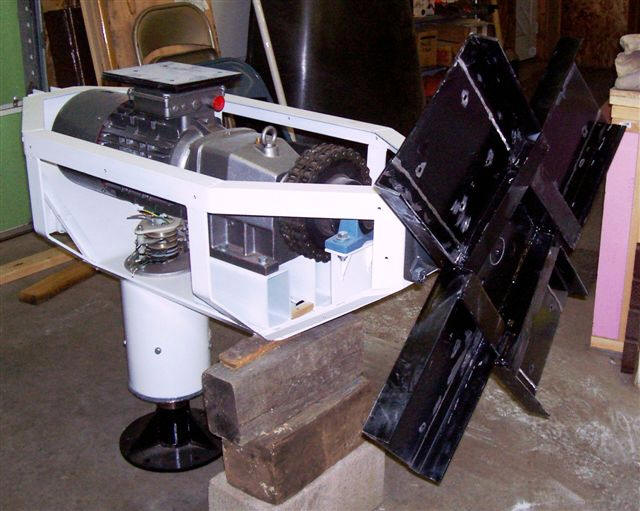
Turbine assembly with the blade support mounted.
October 20, 2008