
Search
The Renewable Energy site for Do-It-Yourselfers
Measuring Output
of A Prototype Solar Collector
The picture below shows a simple
setup to measure the output of small test solar water collector.
The aim was to see how well CPVC pipe
and extruded aluminum "heat spreaders" as used in the radiant floor business
would do as an easy to build solar collector.
I wanted to measure the thermal
output of the collector, and to get an idea how efficient the heat transfer was
from the alum extruded fins to the CPVC pipe.
In this setup, water is pumped by a
small submersible pump in the bucket through the collector and back into the
bucket. The performance of the collector can be determined by measuring
the flow rate, temperature in and temperature out.
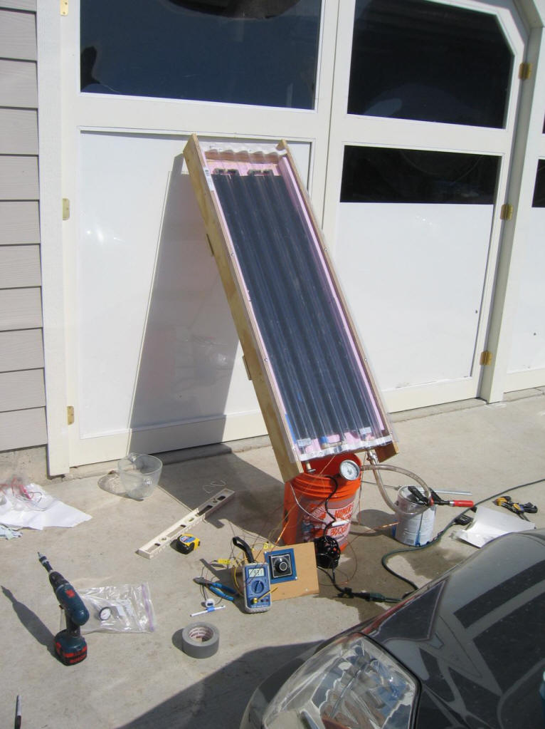
In the picture:
-
Digital multimeter to measure
temperatures from thermocouples.
-
Multi position thermocouple switch
that allows the meter to read any one of half a dozen thermocouples on
the same multimeter easily by just turning the dial
-
Clamp and tubing to restrict the
flow rate from the pump (located in the bucket)
The output of the collector is:
Qout = (Tout -
Tin) (Flow Rate ) (Specific Heat of Water)
In this case, Tout and Tin were
measured with thermocouples that were placed near the pump inlet and in the
outflow pipe. Ordinary hardware store alcohol thermometers could also have
been used.
The flow rate was measured by timing
how long it took to fill up the 2 quart mixing bowl in the picture. This
is very accurate (better than most flow meters). The clamp on the
hose was used to adjust the flow rate to get a reasonable temperature rise.
As an example:
Flow rate = 0.5 gpm
Tin = 91F
Tout = 98F
Then Qout = ( 98F -
91F)(0.5 gal/min)(8.2 lb/gal) (1.0 BTU/lb-F) = 28.7 BTU/min or 1720 BTU/hr
In addition to measuring flow rate,
thermocouples were placed on the outer edge of the extruded fin, the middle of
the fin, and on the CPVC pipe wall near the fin. This gives an idea how
much thermal resistance is in the alum fin vs how much is in the connection from
the fin to the pipe wall. The thermocouples were of the type that has an
adhesive pad that can be stuck onto the surface whose temperature is to be
measured. These thermocouples are in the neighborhood of $10 each --
not too expensive.
Here is one way to estimate the
efficiency of the collector:
- Set up as shown above.
- Point the collector due south, and
tilt it so that at noon it is approximately perpendicular to the sun.
- Do the test on a very clear day.
- Start measuring the output of the
collector a few minutes before solar noon, and measure it repeatedly until a few
minutes after solar noon.
- Average the measurements to get a
good estimate of the output at solar noon.
- Look up the solar radiation on the
collector in a handbook for your latitude and for the date of the test.
These tables are included in the back of many solar reference books.
The efficiency is:
Efic = (Measure heat output)/(Looked up Solar Input)
You can compare this to similar
collectors documented at the NRCC site to see how well your collector is doing.
The total outlay for the instrument
setup shown here is around $100.
If only the collector output was
needed, just as good a job could have been done with a couple of $2 hardware
store thermometers. This very small outlay for instruments and simple
testing can be a big help in determining if your collector is working well, and
in evaluating the effect of design changes.
Building and testing a small working
prototype like this can often save a lot of money and time by pointing the way
to a better design.
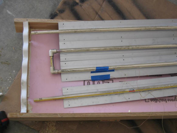
The thermocouples that measure the
fin temperatures being mounted on the back of the fins (under the blue tape)
Note that the PVC glazing and the
polystyrene (pink) insulation I used for this little test are both very bad
choices for real collectors -- they melt.