Search
The Renewable Energy site for Do-It-Yourselfers
Building the
Aluminum Soffit Solar Air Heating Collector
| This is part of a program to test several
solar air heating collector designs for performance... This
collector design uses vented aluminum soffit material as the absorber.
The air enters at the center bottom of the collector, where an aluminum
baffle spreads the flow across the width of the collector on the glazing
side of an absorber made from vented aluminum soffit material. The
air rises up between the glazing and the absorber, and eventually finds
its way through one of the holes in the vented absorber and flows to the
back side of the collector. The air then flows up the back side of
the collector to the exit vent located at the top of the collector.
This aluminum vented soffit absorber scheme was invented by Laren
Corie, and the construction follows
his basic guidelines. Some of the construction details are
different, but I tried to stick to Laren's recommended geometry.
Back to the Solar Air Heating Collector test program home.. |
|
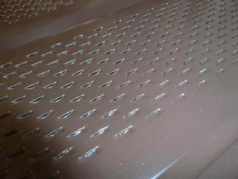
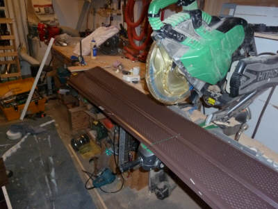
The next few pictures show what the
aluminum soffit material the absorber is made from looks like.

Soffit vents from the finished side. |
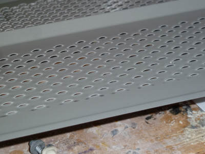
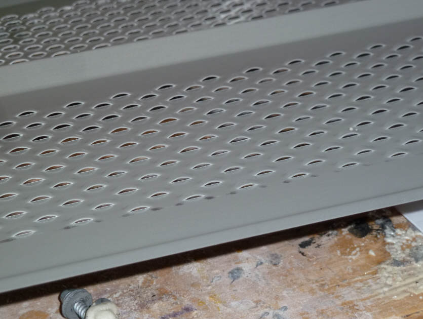
Soffit vents from the back side. |
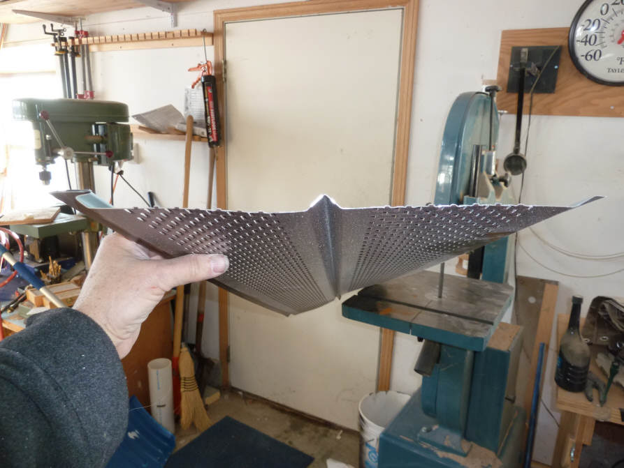
An end view. |

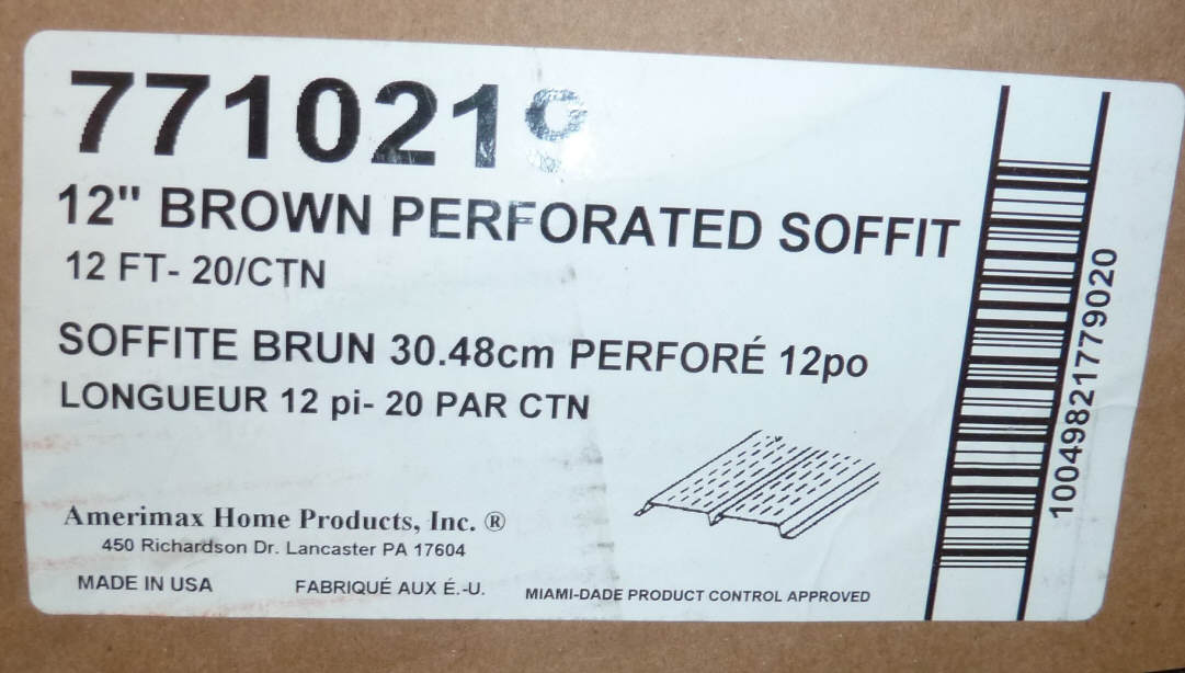
This is the soffit material I used. I got this from Home Depot, but did
have to order a full box.
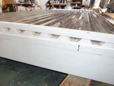
The first part of the construction is
the same as the Reference collector -- I
basically built a box with an insulation board back, 1 by 6 sides, and 2 by 6's
for the top and bottom sills as shown just below.
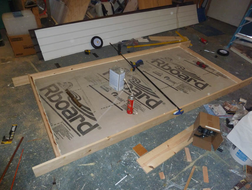
For the soffit collector, you need
the dimension from the back of the glazing to the bottom of the box to be about
4 inches. Since I was starting from the "Empty Box" collector,
which was only about 3 inches deep, I added an inch of depth by gluing on one
inch wide strips to the sides and top and ends.
Vents
You can also see that the collector I
started with had its vents on opposite corners, and since the soffit collector
wants vents on the centerline, I filled the old vent holes in with insulation
plugs and Great Stuff, and cut new vent openings on the centerline.
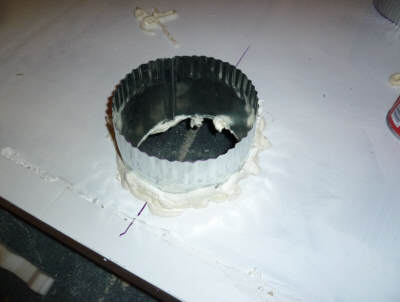
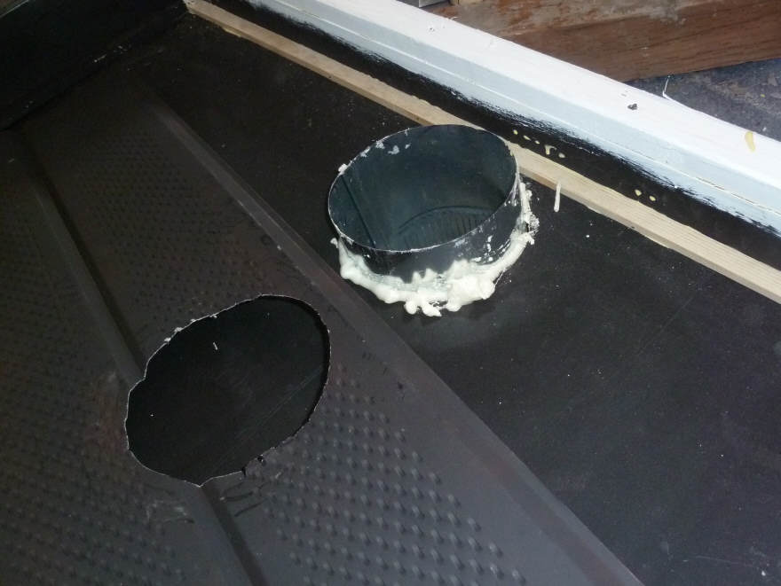
This is one of the new 6 inch diameter centerline vents. |
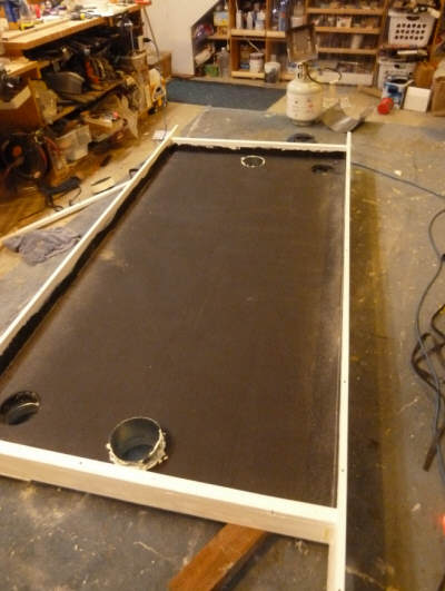
Shows the two new centerline vents and the two old vents before they
were plugged. |
All the vents are foamed in
place with Great Stuff to avoid leaks.
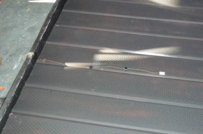
Absorber
The soffit absorber is far from
glazing at the bottom of the collector (where air enters), and is close to the
glazing at the top of the collector where air exits.
The idea is that most of the flow is
on the glazing side near the inlet end of the collector, and most of the flow is
on the back side of the absorber near the outlet end of the collector, so
sloping the absorber allows the depth of the flow path to match the flow rate.
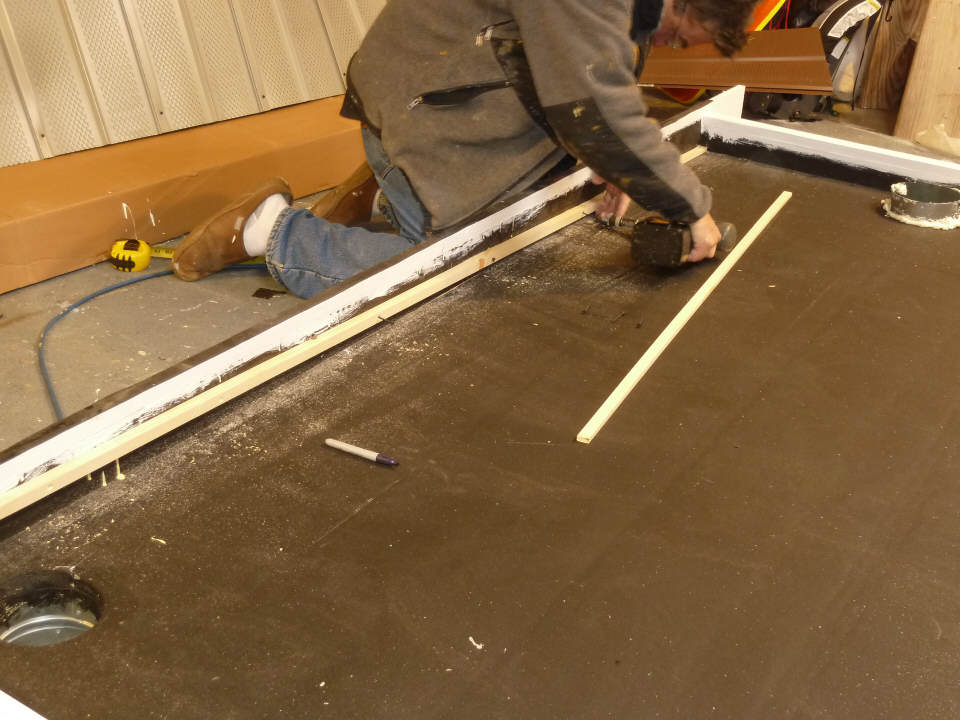
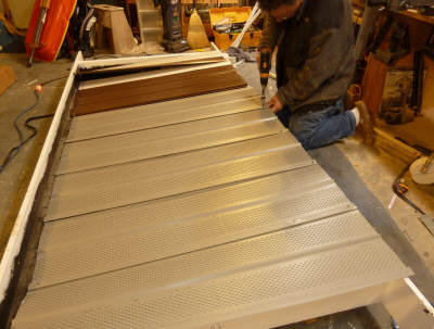
I supported all edges of the soffit
absorber with wooden strips as shown in the next pictures.
The absorber support strips being
attached to the collector box sides.
The depth from the top of the strip to the back of the box is 3 inches on the
outlet end of collector, and half an inch near the bottom end of the collector.
This means tapering the support strip down to half and inch on the inlet end.
Outlet end |
Inlet end |
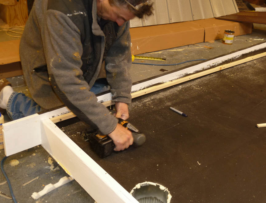
The two wood strips to support the
ends of the absorber go in the same way.
You will need enough of the soffit strips cut a little narrower than the inside
width of the collector box to fill the collector from top to bottom.
You may also want to cut an extra
piece for the inlet baffle.
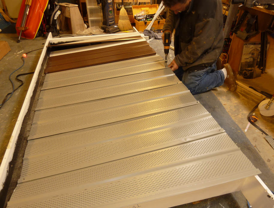
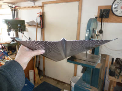
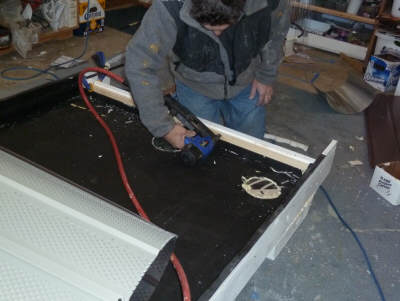
This shows screwing the absorber
pieces together with small self tapping screws just to hold it into a single
unit.
The absorber is upside down in this
picture.
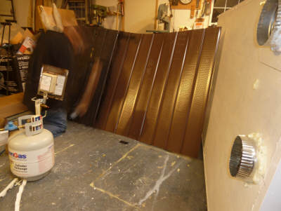
I sprayed the sun side of the
absorber with black Rust Oleum BBQ paint at this point.
I'm moving so fast you can't even see
me :)
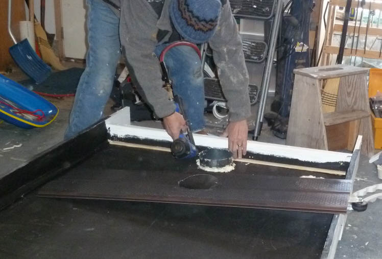
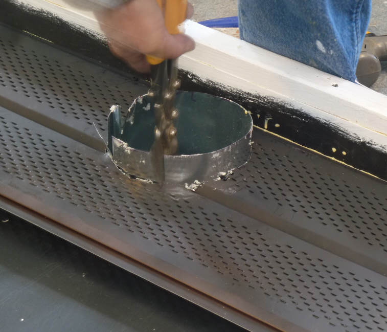
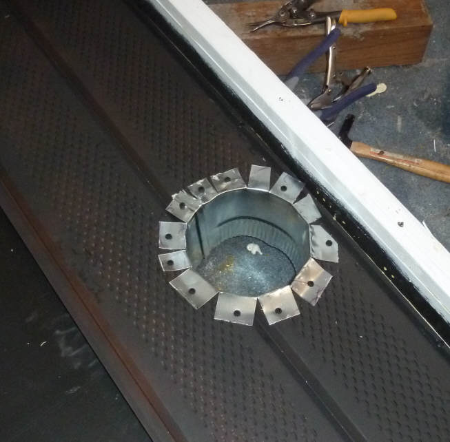
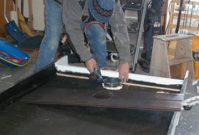
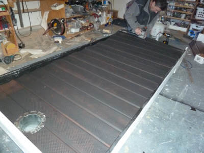
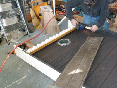
The inlet duct penetrates the
absorber so that the inlet air is delivered to the glazing side of the absorber.
The pictures show how I did this.
I cut a hole in the first soffit
section that allows the inlet duct to pass through the soffit, then cut tabs in
the part of the inlet duct that penetrates the soffit, bent the tabs back and
screwed them to the soffit.
Be sure to seal the inlet duct where
it penetrates the back wall of the collector.

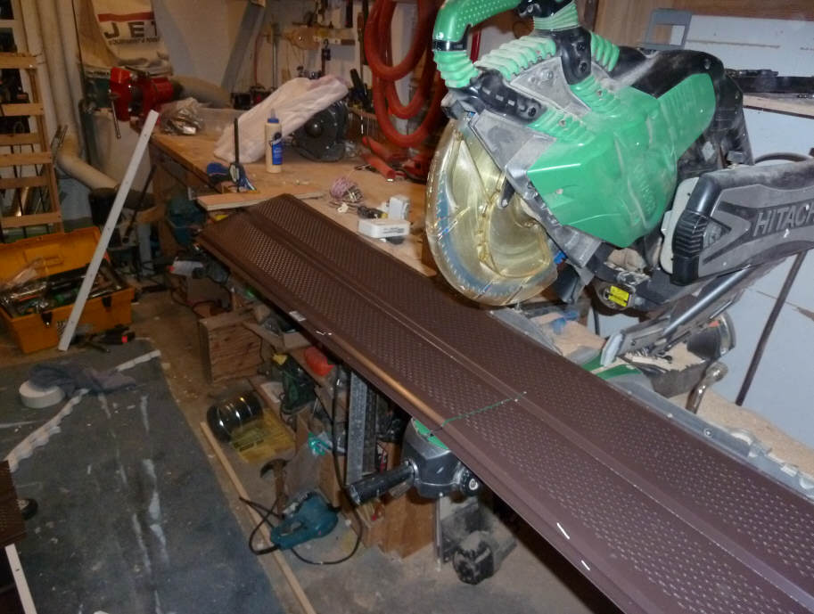
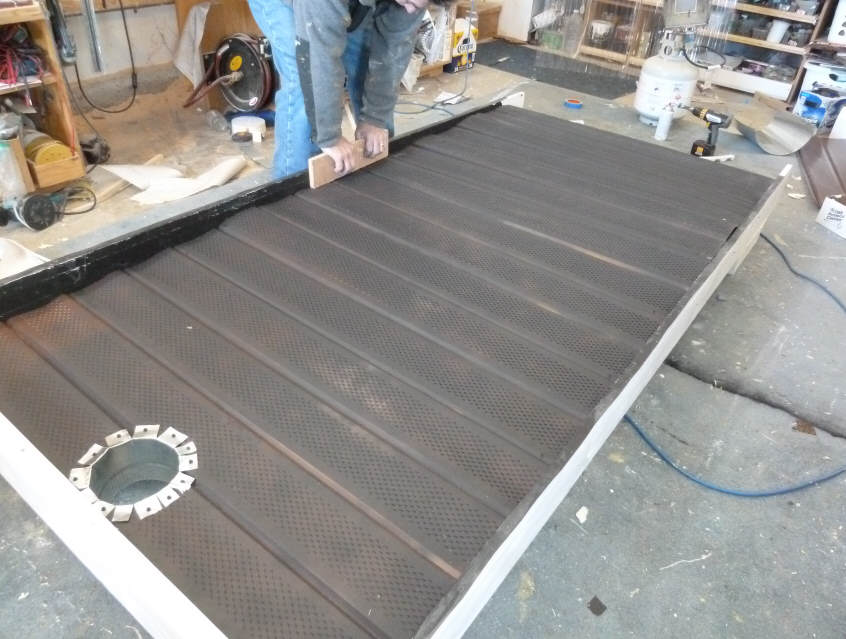
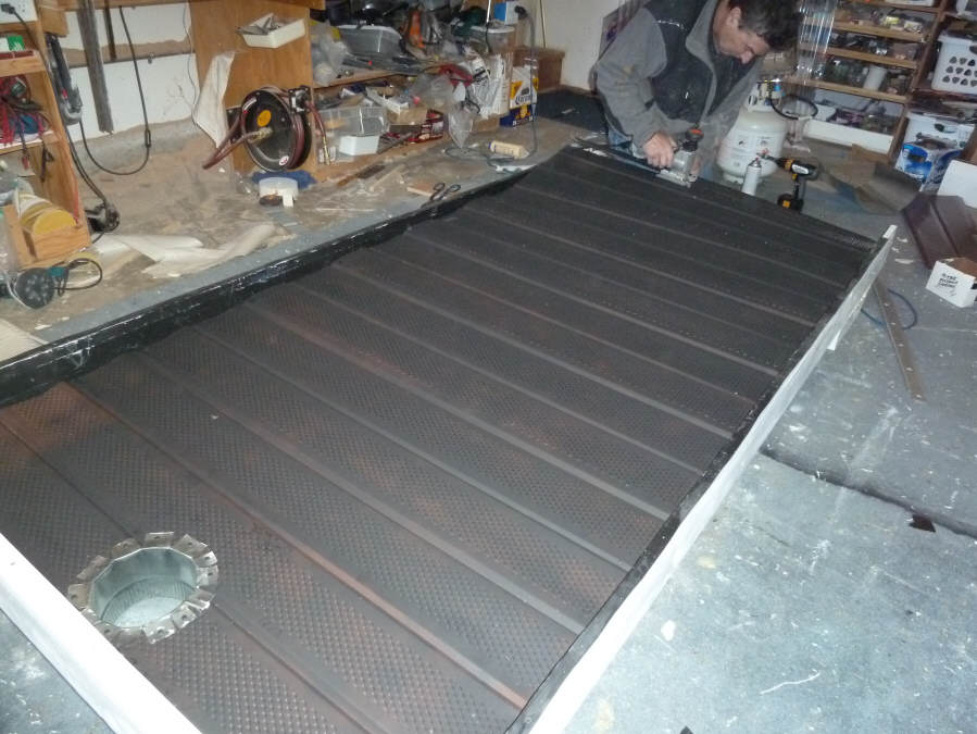
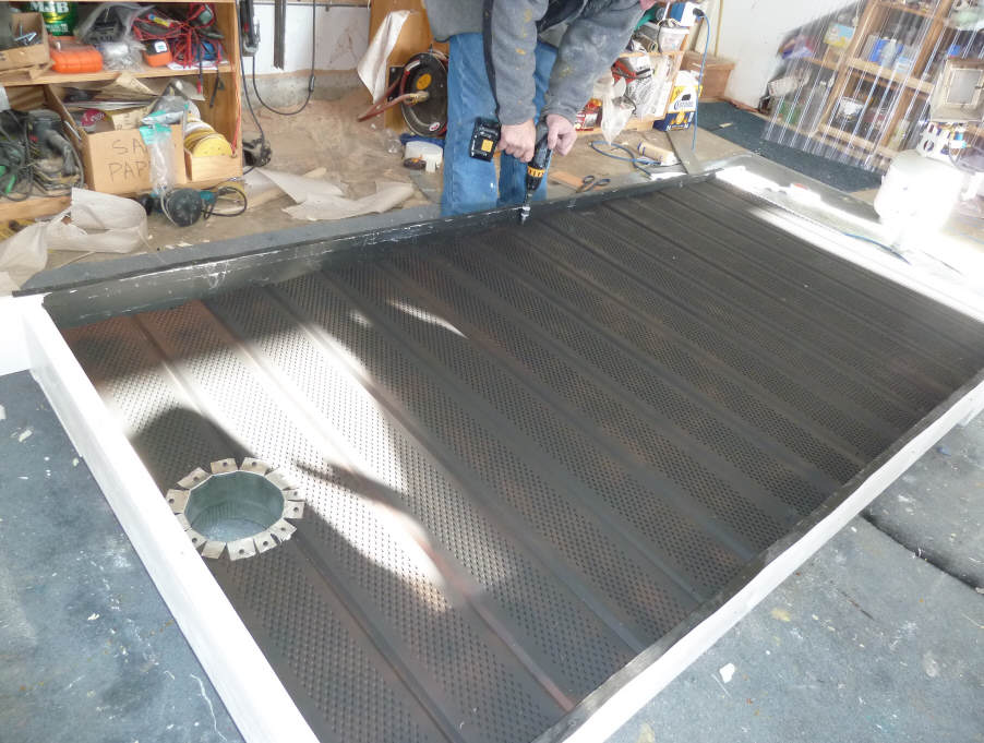
Tapping the absorber down onto the wood support strips. |
Cut the last sheet off to fit. |
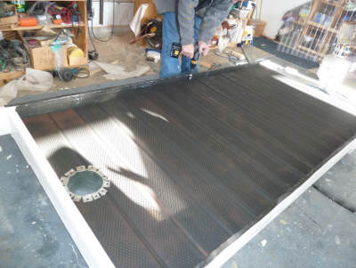
I used a couple screws per soffit panel to hold them to the wood strips. |
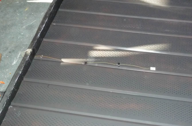
I installed a surface mount thermocouple on the absorber surface -- this is the
time to get anything you want for measurements into the collector.
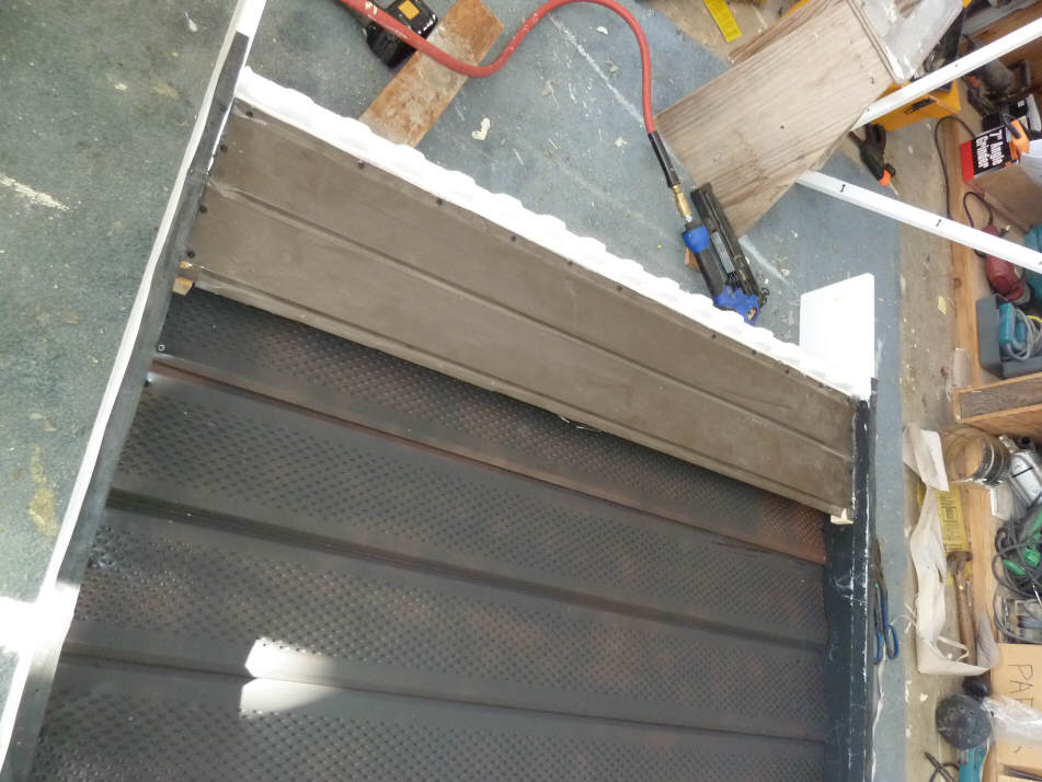
A baffle is needed at the bottom of
the collector to deflect the entering air and spread it out across the width of
the collector.
I used a scrap piece of unvented
aluminum soffit, but you can use a piece of vented soffit if you tape the vent
holes shut with aluminum tape and flatten out the vents.
The baffles should be positioned
about half an inch from the glazing.
I bent the upper edge of the baffle
into a lip that extends away from the glazing. Laren feels that this
helps to spread the flow.
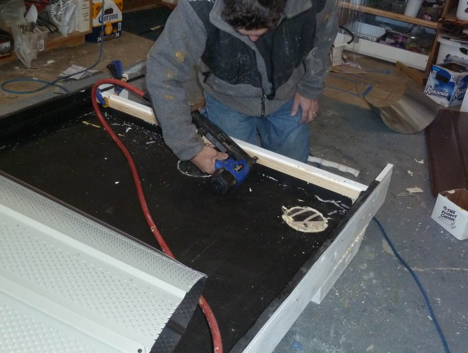
Installing the wood support strips that support the baffle |
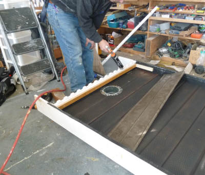
Sealing the edges of the baffle. |

The finished baffle screwed down to
the support strips. |
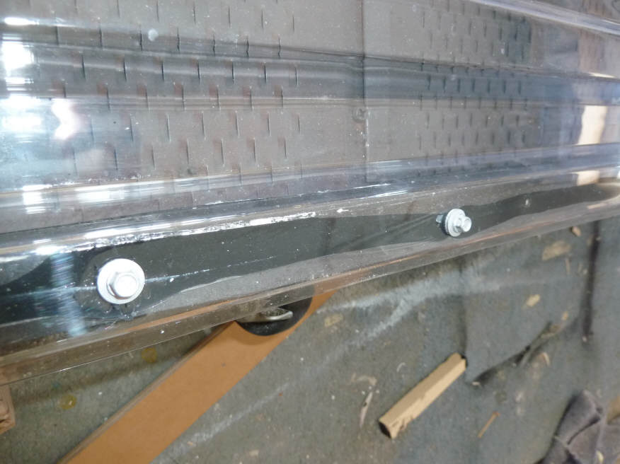
Glazing
The glazing is done in the same way
as for the reference collector, except in this case, I sealed the glazing to the
box with silicone caulk to insure no leaks.
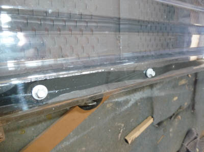
Edge corrugation sealed to box, and closely spaced
fasteners. |
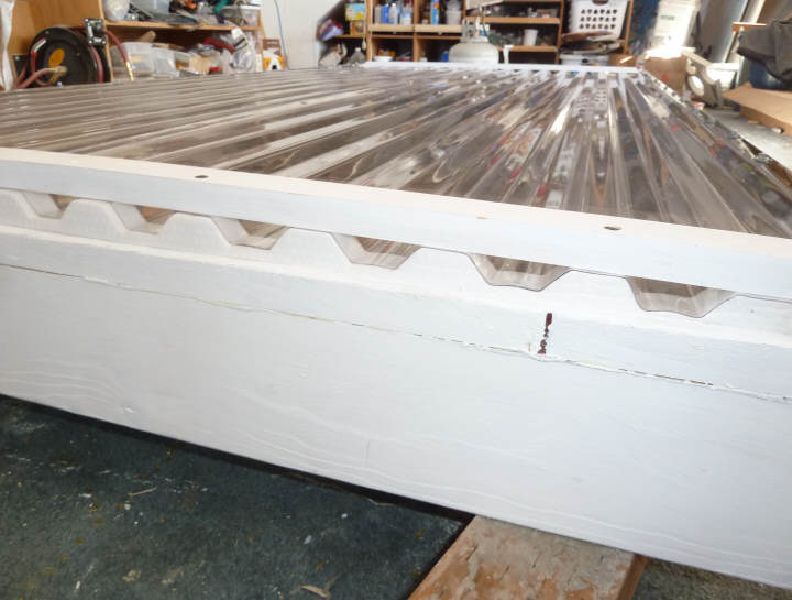
The ends are done with the usual foam strips and
a compression bar to insure a good seal. |
Gary January 4, 2011