Search
The Renewable Energy site for Do-It-Yourselfers
Solar Water
Heating Using a Unique Master and Slave Collector Design
Gordon describes his new solar water heating system. It is
loosely based on our
$1K solar water
heating system, but includes some really interesting and helpful
innovations including:
- A unique "Khanh" collector design that utilizes a large slave
collector to improve the performance of a smaller master collector.
- A new tank design that makes use of a
galvanized stock tank lined with EPDM, well insulated, and low
profile.
- A very nice and compact multi-coil
copper heat exchanger.
- Some techniques for improving drain
back on systems with marginal drainage slope.
Gordon shows a great deal of ingenuity in
working out a way to install a water heating system that works well and
looks good into a very difficult situation.
Thanks very much to Gordon for sharing
this!! |
|
Update 3/30/2013: Two Year Update from Gordy
A very complete update after 2 years of service covering: performance, pumps, plumbing updates,
the backup heater, the new differential controller, and more...
Adding Solar Water Heating:
In a prior ‘schoolhouse
retrofit’ article, we mentioned an intention to eventually construct a solar
domestic hot water heater. The project is now essentially completed and we are
happy to describe the difficulties we faced, the choices made and the resulting
preliminary performance.
Being essentially out of sight and out of mind, the typical water heater seems
often to be taken for granted. However, the energy consumption of a water heater
is really quite significant. By undertaking the deep energy retrofit, we thought
we had made a fairly major effort to reduce our energy footprint. Since then,
Ontario has introduced time of use smart metering and stiff increases in
electricity pricing. As a result of the retrofit, our electricity consumption
was down considerably – but the monthly billings remained relatively constant.
Even though we had lowered the thermostat on the electric water heater to about
115 degrees F., installed a mechanical timer (restricting powering the water
heater to night-time use), and primarily powering the heater with 115V rather
than 230V (¼ power) - the water heater still consumed nearly 3000 kWh per year!
Of our total electric consumption, about 60% was a result of the water heater!
Drooling with envy regarding Gary Reysa’s
$ 1000 solar heater
described on his “Build-It-Solar” web site, we decided that we too, would make
the plunge.
Gary’s drainback system involves a water storage tank open (essentially) to the
air, a small pump is used to lift the water to the top of the collector, and
gravity is used to return the warmed water to the tank. If the collector is no
longer warmer than the tank, the pump is deactivated and the water drains out of
the collector – providing cold weather freeze protection even in cold climates.
Ideally the solar water storage tank is located close to a normal hot water
heater and cold water is routed through a coil in the solar storage tank to
preheat the water prior to entry into the normal hot water heater. For added
performance, Gary has sized the coil, so that under most situations, the heat
exchanger operates at maximum efficiency.
We are of the opinion that simplicity and ruggedness are the key features of an
elegant design. Gary’s concept of a solar drainback system composed of
inexpensive, easily obtained common parts is a classic. We approached the
project knowing that we couldn’t improve upon his design – but could we achieve
near equal performance in view of the tough constraints of our situation?
Tough Constraints:
The house is located in a relatively
cold climate that experiences considerable rain and snow, and sometimes, high
winds. Winter to summer temperature differentials are significant and result in
major thermal expansion/contraction of roofing. One is advised to avoid complex
roof designs and roof penetrations if possible. Placing a collector on the roof
is just not advisable.
The cold water pressure system and hot water tank were located near a north wall
in the utility room – a great distance from any feasible collector locations.
There was no space available in the utility room for a solar storage tank. The
closest feasible location was an adjacent room – but this would involve about 68
feet of inter-connecting PEX and the resulting substantial heat losses.
There were only two feasible locations to locate the collector – and both
involved serious concerns. The two possibilities were actually adjacent
one-another on the southerly wall of the house, one facing due south and the
other 30 degrees east of south. Unfortunately for the location facing due south,
the garage shaded the location by mid-afternoon during the wintertime.
Unfortunately for the east of south location, mature trees shaded the location
in early morning, particularly in early summer. Both locations involved a
distance of about 65 feet from the only potential location for a water storage
tank – that’s a least 130 feet of PEX tubing and involves serious heat losses. A
separate solar collector/garden shed was possible, but would involve
considerably more piping and heat loss.
Click on pictures for full size.
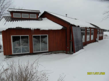
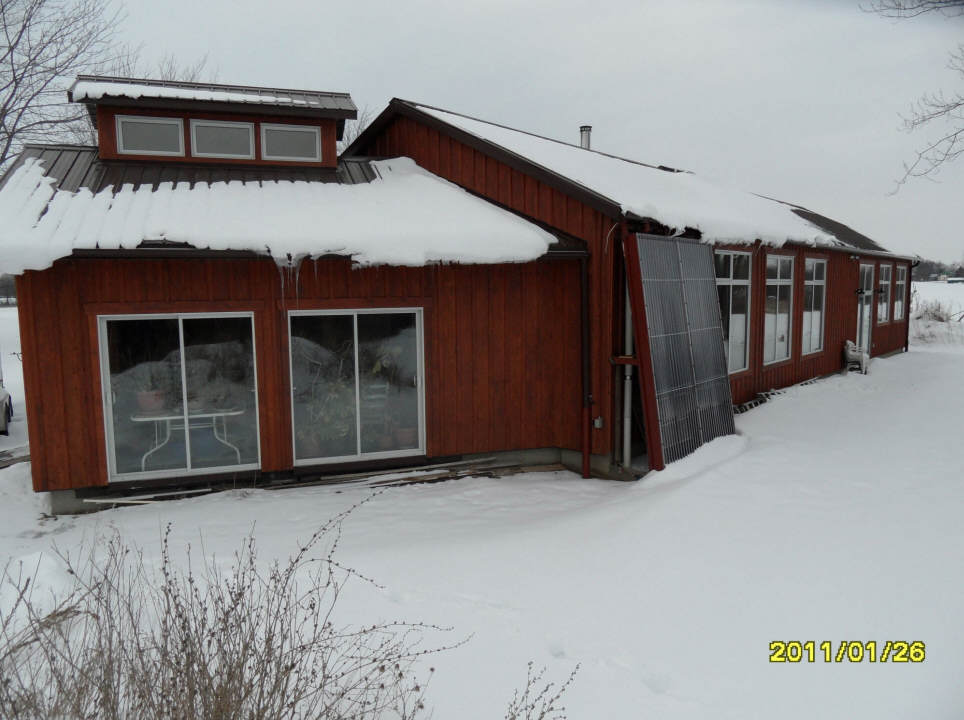
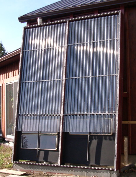
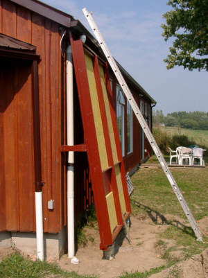
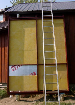
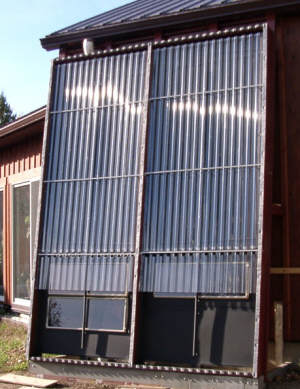
The new solar water heating collector
just to the right of the new sunspace. |
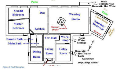
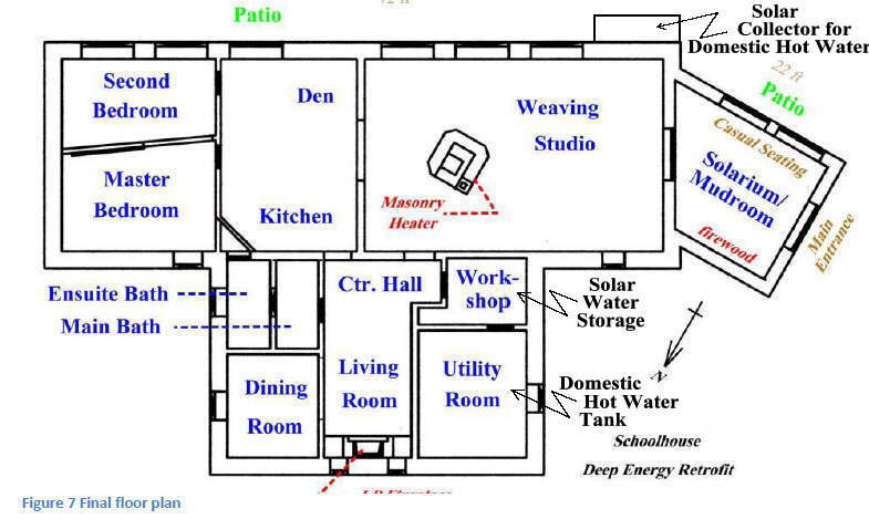
The layout of the converted schoolhouse
showing the collector and tank location.
|
Being an old schoolhouse, there is neither basement nor crawl space to locate
the storage tank. A roof location for the collector was not acceptable.
Together, this meant the tank would have to sit on the main floor and the
collector would have to be mounted to the wall. This would restrict the gravity
return to being from the bottom of the collector to the water level at the top
of the storage tank – a very small vertical distance over a very long horizontal
distance.
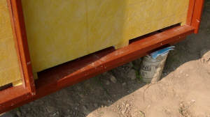
The gravity return must completely empty the collector to avoid freeze damage.
Piping between the outside wall insulation and the collectors must be well
insulated and provided with considerable slope to ensure that the static water
level would be well inside the wall (in the heated house). This suggested that
the static water level had to be at least 12 inches lower than the bottom corner
of the collector manifold.
To minimize heat loss, a cubic (or better still a spherical) water storage tank
is preferable. In our case, the height of the water level was severely
constrained, so we had to consider a very low, long tank design. This would
involve a much greater total surface area, much more insulation, and more
thermal heat loss than usual.
There were very few routing opportunities for the PEX tubing between the
collector and storage tank. One could go up across the unheated attic – but
gravity drainage of the collector could not be achieved. One could construct an
exterior insulated trench around the house – but we would be intercepting at
least a dozen electrical, water and drainage pipes along the way. Anticipating a
possible use, during the renovation we had threaded a 4 inch “Big O” (and pull
rope) through an original concrete sub-slab heating duct. One end was near the
potential collector location, the other, relatively close to the preferred tank
location. Both ends would involve some breaking-up of the concrete floor.
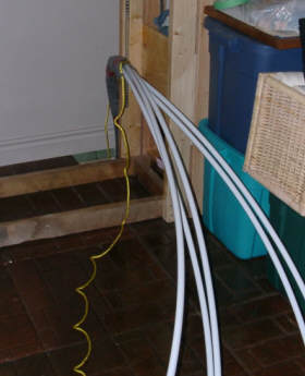
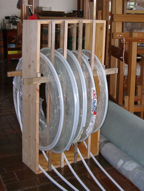
Bundle of 5 half inch diameter PEX
tubes being fed into the
under slab "Big-O" duct. |
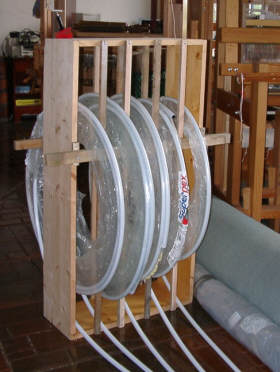
Uncoiling the PEX during
the under slab pull. |
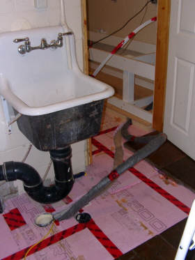
The PEX bundle pulled into
the storage tank area. |
This 4 inch “Big O” actually involved several relatively tight corners. Ideally,
two heavily insulated 1 inch PEX lines out to the collector would be desirable.
Such was out of the question! We would have to make do with four ½” PEX lines
and no insulation (two out, two return). Actually, we used five ½” PEX lines
(the fifth used for a sensor wiring chase and spare should damage occur to one
of the others). The five lines were wrapped and taped with landscape cloth to
protect the PEX. The PEX bundle was pulled in one difficult ‘go’. We got it
inches from where we wanted it, took a minute’s breather, but it would never
budge from there again! We made do. The heat loss from this pipe run would be
bad – but there didn’t seem to be a feasible alternative. As this route was
under the slab, another implication surfaced - it would never actually drain.
In summary, the constraints of our situation were truly abysmal. This would be a
hell of a test for a drainback solar hot water system. If it were to prove to be
feasible in our situation, it should be much easier for just about everyone
else!
The Collector:
When undertaking the preliminary
research for our passive solar and deep energy retrofit, we collected together
and read several dozen books on the topic. Many were old and out of print. Most
people would consider this effort a waste of time, as so many of the efforts of
the ‘60s and ’70 had serious shortcomings. I was surprised to realize that many
of the early concepts are valid, more so now, than when proposed - now that we
have substantial improvements in various building materials. One book I truly
fancied was “New
Inventions in Low-Cost Solar Heating – 100 Daring Schemes Tries and Untried”
by Professor William A. Shurcliff, Brick House Publishing, 1979, ISBN:
0-931790-02-6. It’s a great book to get one out from under the suffocating cloak
of conventional thinking.
On pages 118-125 of this book, Dr. Shurcliff describes a concept invented in the
early ‘70s by Dr. Dinh Khanh of Gainesville, Florida. The elegance and
simplicity of his concept is riveting. In a nut-shell, he suggests that, as
active solar collectors are rather expensive to purchase or build (on per square
foot basis), why not make best use of such collectors by substantially improving
their efficiency and/or reducing their thermal losses! His proposal is simply
the construction of a much larger, but inexpensive, passive air collector
(slave) over the active (primary) collector – putting the active collector in a
‘hot house’! More technically, the inexpensive slave collector provides a warm
environment around the expensive primary collector – so that it has far lower
thermal loss to the outside, and thus performs at a much higher temperature than
would normally have occurred. The concept is simple, yet open to many ways of
actually doing so.
The problem we faced with our collector was that the location limited us to a
nine foot width. The height was limited by the eaves trough down pipe and
effects of snow accumulation. The bottom was severely constrained by the
requirement of gravity drainage to the other side of the dwelling. The allowable
collector area was smaller than desirable for a system operating under ideal
conditions - and our situation wasn’t even remotely similar to ideal conditions.
Due to the thermal losses of several hundred feet of PEX, we needed a collector
much larger than normal, perhaps double in size – but it was just not possible!
We had no information as to whether
anyone had ever successfully tried Dr. Khanh’s idea, but we decided to attempt a
variant of the concept.
The collector is two 4ft wide units,
side-to-side, about 10 ½ ft tall, steeply tilted to the side of the house. As
the storage tank sits on the interior floor, the requirement for gravity return
flow restricted copper risers to the upper 2/3s of the collector – the primary
collector. The basic construction is conventional - ½” copper risers on 5”
centres, ½” copper manifolds top and bottom, and black painted, hand formed
aluminum fins screwed and silicone glued to a plywood base panel. The lower 1/3
of the two collectors is a ‘slave’ - simply black painted aluminum screwed to
the plywood base panel. Behind the plywood bas is a layer of fiberglass ceiling
panels (for high temperature insulation), then a 1 inch thickness of foil faced
urethane.
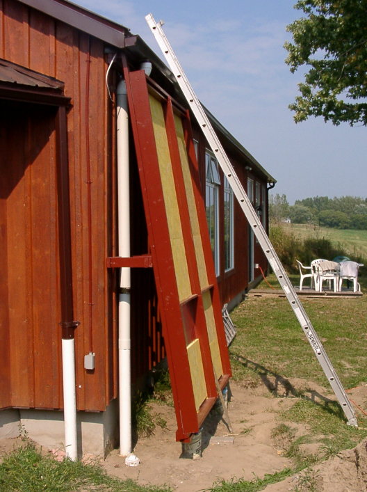
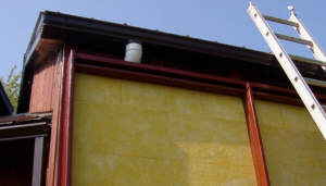
Side view of collector.
The gutter and gutter drain constrain
the height of the collector. |
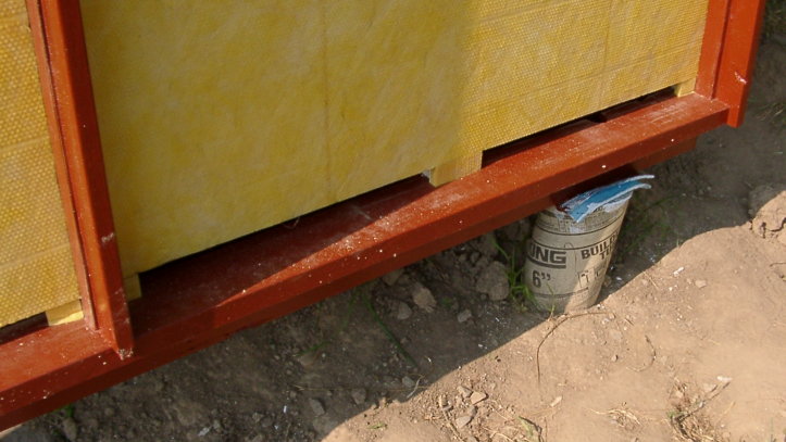
The fiberglass ceiling tiles being placed
over the foil faced urethane insulation board. |
The variant of the Khanh concept we
decided to construct involved a single glazed ‘slave’ physically below a double
glazed active collector (‘primary’). Hot air generated in the lower slave
convects up between the one inch gap between the glazing layers on the front of
the active collector. A slot in the top of each module and a wooden baffle
conveys this warm air stream to the rear of the active collector.
|
The lower slots for air circulation in
the slave collector. |
The upper slots for air circulation in
the slave collector. |
The two modules are supported by five 2 by 4 studs leaning against the house. 1
½” XPS foam insulation was glued and screwed to the rear of these studs across
the back of the modules. This insulation, in conjunction with the 2 by 4s and
insulated plywood base of the collectors, creates four vertical air channels
down the back side of the collectors. Each of the four air channels has a
cross-section of about 1 1/2” by 21”. The air heated by the slave collector gets
conveyed down these channels and routed back to the slave at the bottom.
In summary, the air warmed in the slave is repeatedly reheated and recycled
around both the front and back of the conventional copper tube/aluminum fin
collector. Thus the conductive and convective thermal losses normally associated
with such collectors are nearly eliminated.
The copper tube with aluminum fin active
portion of the collector on top. |

The three PV panels are installed
in the slave collector area. |
For the glazing material we chose Palram Suntuf. Two 8 foot lengths for the
inner glazing and two 12 foot lengths cut to 10 ½ feet for the outer glazing.
Hopefully it has the level of UV resistance claimed by the manufacturer. The
vertical corrugations provide stiffness and stability, but additionally seem to
improve light transmission at acute incidence angles.
We had three small PV panels (nominal 15W each) not doing anything useful. They
were mounted in the slave collectors with the hope that they might power the
circulation pump. Actual performance of the PV panels is significantly lower
than the rated output – perhaps 1 ½ to 2 amps at around 17V. Not good enough!
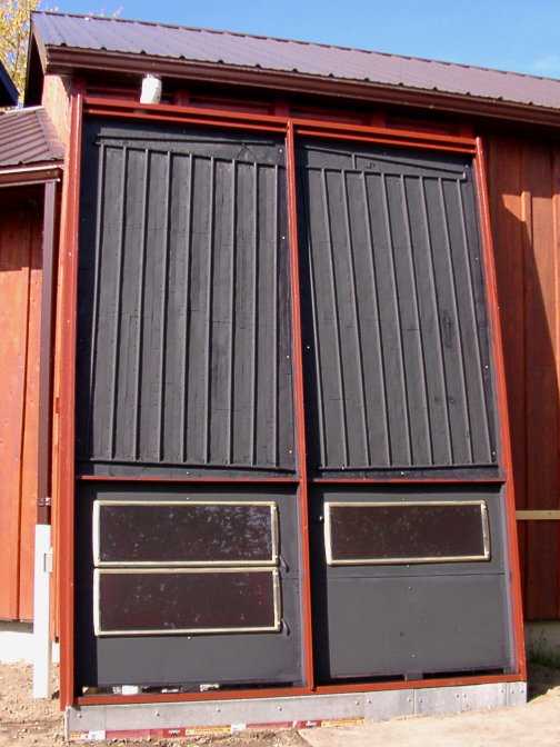
The inner Suntuf glazing panels installed.
Note the vent holes above the PV panels. |

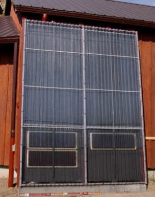
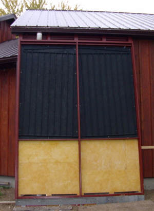
The finished collector with the active section on top and
"slave" collector extending to the ground.
Total size is 8 ft wide by 10 1/2 ft high. |
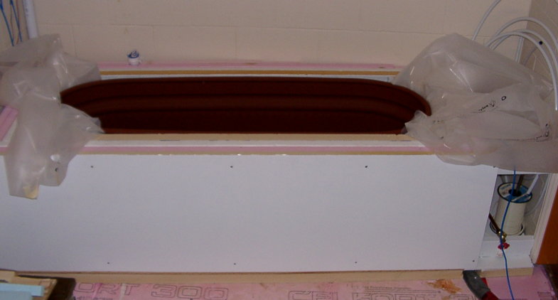
Thermal Storage Tank:
The storage tank sits on a 2”
thickness of foil faced urethane, laid over 1 ½” of Type IV XPS foam directly on
the original concrete slab. The four sides are insulated with 2” of foil faced
urethane and 3” of XPS. As the tank resides inside the home, the risk of
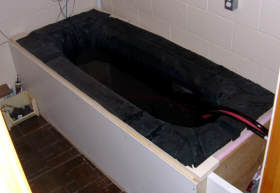
tank leakage/failure was a major concern. After much thought, we purchased a
galvanized farm stock trough, and then proceeded to coat it with five thin
layers of EPDM paint to further protect it from corrosion. The tank was then
lowered into four layers of poly (standard vapor barrier). The tank was then
lined with an EPDM pond liner like the usual “BIS $1000 drainback” tank design.
A heavy wooden frame of 4 by 4 corners posts and 2 by 6 upper and lower rails
surrounds the stock tank providing support for the side insulation and
conventional foam insulated, plywood top (with pond liner). Hopefully this
configuration will provide a longer life than typically expected of the usual
plywood box arrangement.
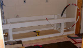
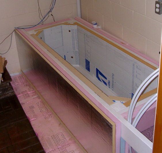
Storage tank frame construction. |
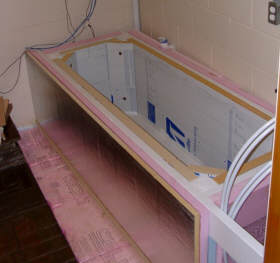
Insulating the tank assembly. |
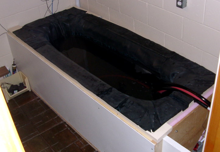
The stock tank installed over
four layers of poly. |
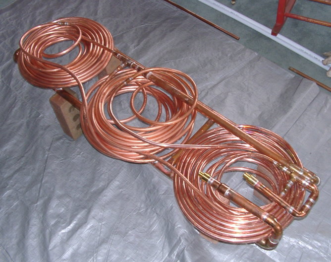
One disadvantage of the stock tank is the rather narrow width. It is too narrow
to consider using 1” or even ¾” coils of PEX as the heat exchanger. We
constructed two 75 foot coils of 3/8” soft copper, configured them in parallel
feeding about 12 feet of 1” copper pipe (folded back and forth). This does not
provide the stored hot water volume we would like, but should provide an
attractive heat exchanger efficiency.

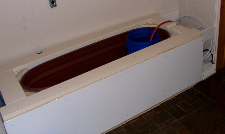
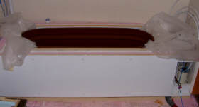
Initial testing with olive barrel. |
Adding rainwater to fill the tank. |
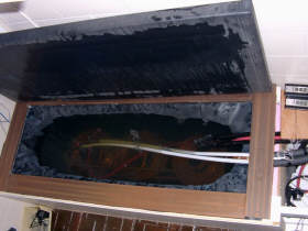
Closing the tank lid. |
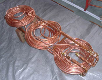
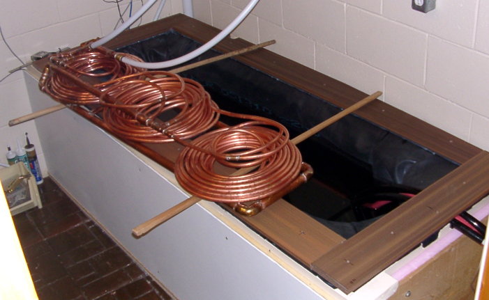
Completed copper heat exchanger.
Two 75 ft coils of 3/8 inch ID copper
in parallel. 12 ft of 1 inch copper pipe
used structural frame and water storage. |
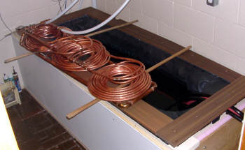
Lowering the heat exchanger into the tank. |
Pump Selection:
One of the few advantages of having
the bottom of the collector a short vertical distance from the tank surface is
that it minimizes the vertical head that the pump must accommodate.
Unfortunately, due to the long distances and narrow tube sizes, head loss due to
pipe friction at start-up is substantial. We went through the calculations and
eventually selected a 12V DC
Swiftech
MCP655 (a computer server pump). It has a variable speed capability, but in
our configuration, maximum speed (about 2 ½ amps) provides slightly less than 2
gal/minute – slightly under the ideal flow rate, but certainly adequate. It is
mounted on very generous sized rubber mounts very near the floor, and coupled to
heavy rubber hoses - the pump is very nearly silent.
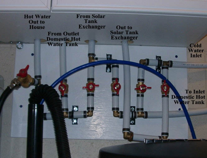
Gate valve choices -- electric heat, or solar heat, or both.
Pump Controller:
I intend to design and construct a
differential temperature controller to properly drive the pump. It has yet to be
decided whether it shall be based upon a BASIC Stamp, an AVR controller or a
conventional comparator circuit.
In the interim, I was hoping that the little PV panels could accomplish a
somewhat similar job. Alas, Murphy was an optimist. This of course was not so.
The PV panels provide perhaps 2/3s of the needed power, but not enough. Trying
to haywire a battery and/or wall wart to power share with the PV panels
presented new frustrating difficulties. For the interim, the PV panels only
trigger an optically isolated, zero crossing, solid state relay, which controls
mains power to a DC power supply (a power adapter for a 13V Koolatron cooler).
Initial Testing:
Murphy was indeed in the drivers
seat. It didn’t work!
When the pump was initially powered up, it just couldn’t raise the water high
enough to get to the top of the collectors. Eventually we realized that there
had been some small bubbles caught in the line - the pump just can’t tolerate
them on the inlet side! Upon purging the line, we were in business. Or were we?
Then we realized that upon stopping the pump, the drainback feature wouldn’t
initiate! In a cold climate that would be deadly! In an attempt to visualize
what was happening at the inlet and outlet of the two collectors we introduced
tees and gate valves (just inside the house) inter-connecting both inlets and
both outlets. Two clear vinyl tubes were connected to see where the water levels
occurred. The lower tube was connected about two feet down from the lower
manifold. The upper tube was connected about mid-way down the copper risers.
Almost by accident we realized that if the valves to the upper tube were left
cracked slightly open, the air break would consistently initiate rapid
drainback. A brief opening of the valve on the lower tube confirmed that the
static water level was confined within the house. During normal pump operation,
the Bernoulli effect at the tees of the cracked open upper valve would draw some
air into the return line but it seemed to have no detrimental effect upon the
gravity return flow. Better yet, even during pump start-up, there didn’t seem to
be a noticeable affect. Just maybe Murphy was on holiday.
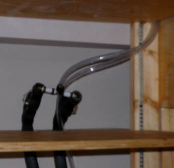
Interior view of the collector outlet and the air
bleed valves. |
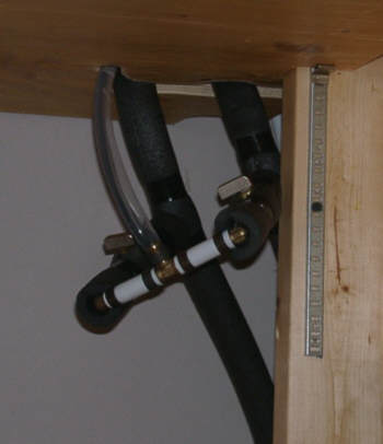
Interior view of the water level indicator
below the the collector inlets. |
Our initial tests involved a small olive barrel inside the tank, as the tank
assembly had yet to be completed. The results, shown on this link here,
surpassed our expectations. Dr. Khanh’s concept seems to have increased the heat
output by about 50% - yet had involved a very low cost!
Finally the tank was completed To complicate matters, we were using rainwater
for the tank/collector circuit. The rain barrel had frozen solid, so we had to
bring in small buckets of water – when and if, small amounts thawed. Eventually
the tank was filled.
Unfortunately, we hadn’t had a sunny day in weeks! Occasionally we had an
opportunity to test aspects of the control system, but with so little sun, the
tank remained cold for weeks more! Over the period the tank water became very
slimy. We start to worry how that could be controlled. When the copper heat
exchanger coils were finally installed, the slim problem disappeared over-night.
We were relieved!
Preliminary Performance:
The system became fully operational
23 December 2010 – but still no sun! It was not until 4 January 2011 that a full
sunny day occurred. In the previous seven weeks we had the equivalent of only 4
short winter days of sun! We expect to have a fair amount of cloud in November
and December, but this had been extreme I guess the moral is that we experience
weather systems, and weather systems don’t necessarily remember to behave like a
sequence of coin tosses over three to five days.
4 January 2011 was sunny, outside temperature hovered at freezing, and winds
were very light. There having been snow the day before, test conditions were
excellent! Throughout the test, the collector temperature exceeded 111 deg. F.,
peaking at 119 deg. F. Starting at 63 deg. F. at 9:10am, the tank temperature
slowly rose to 101 deg. F. by 2:30pm. Then the pump control shut down. About 98
gallons of water had been raised a temperature of 38 deg. F. That’s equivalent
to 31,600 BTU over 5.33 hours (or about 5930 BTU/hr). The active collector is
52.96 sq. ft, thus the heat output is equivalent to about 600 BTU/sq ft of
active collector per mid-winter day.
Conclusions:
Assuming this winter day’s test is
representative of sunny day production throughout the year, the solar collector
can be expected to produce about 75% of the annual hot water need. If the
initial testing is indicative of somewhat warmer weather performance, this is
likely to be a major underestimate as warm weather production should be
significantly better. A solar portion exceeding 85% annually would not be
surprising.
If Dr. Khanh’s solar collector concept can be adapted to your situation, it
would appear to be well worth the small cost and effort!
No, we weren’t able to construct the system for $ 1000. The cost may well have
been double. It should not really be surprising as the purchasing power of the
U.S. dollar for building materials, far exceeds that of the Canadian dollar.
It’s definitely not a weekend project – more like five months, but not rocket
science. Thanks Gary for the inspiration.
If we can make a high quality, solar hot water heater work in our abysmal
situation – you can too!
Go for it!
Gord & Sue Scale,
Email:

Note: Gordon is logging systems performance and will send in a one year report
after the first year of operation.
9 Jan. 2011
Some thoughts on Gordon's solar water
heating system:
- The use of the Khanh collector
is very interesting. Its the only actual application I know of of this
concept. It will be very interesting to see how the performance works
out -- I'm inclined to think it will result in a significant improvement.
This has got me thinking
about a free standing version of the $1K solar water heater, where the
collectors and tank would be integrated into a small shed like structure
that would sit against the south wall of the house, or nearby the house.
The collectors could use the Khanah design with the active part of the
collector extending from the top of the tank upward, while the slave
collector extends all the way to the ground.
Gordon's comment on
the free standing versions is that if you want solar hot water, but
don't plan to stay in your current house, that this kind of free
standing installation could be mounted on trailer wheels. You
could take it with you when you move!
- Its (maybe) worth noting that
while the plan to solar power the pumps has not been successful yet, the
Swiftnets pump only uses about 24 watts. This gives an COP under good
sun conditions that is over 100!
- Gordon worked out a very
innovative way to insure that his collector drains back when the pump
turns off. I would caution people that if you have a situation that is
marginal for draining back reliably that you put the time into making
absolutely certain that your system does drain back as Gordon did. A
frozen and burst collector can ruin your whole day!
- I share Gordon's enthusiasm for
Dr. Shurcliff's “New Inventions in Low-Cost Solar Heating – 100 Daring
Schemes Tries and Untried” book. Its my all time favorite solar book.
Dr. Shurcliff allowed me to scan the out of print book and make it available
for anyone to read --
its here... great reading for people interested in solar
innovation.
- Note the comment in Gordon's
article about the growth in the tank clearing up when the copper heat
exchanger was added. Maybe introducing some copper into storage tanks,
or using one of the copper based treatments is a good way to avoid any
tendency for growth in the tank? I find in my tanks that as long as
the tank temperature gets up above 140F once in a while that growth is
minimal to none, but the copper may be a good additional measure.
- Gordon used a galvanized metal
stock tank with several coats of a paint on EPDM paint, followed by an EPDM
sheet liner. In addition, several layers of poly film were used
outside the tank as a final protection against leaks. Gordon
wanted all the leak protection he could get because of the tank location.
But, I wonder if for most applications where the tank is located in a less
critical area (like a basement or crawl space), if the galvanized stock tank
plus several coats of the EPDM paint would not be a good way to go? It
would be less labor and would eliminate the cost and somewhat fussy job of
install the EPDM membrane.
Note that galvanized stock tanks also come in round versions, which would
easily accommodate a large coil of PEX style heat exchanger, but the round
tank would be more difficult to seal the lid to as you could not use the
wood sill around the tank for a seal surface.
Gordon notes that the EPDM
paint peformance was not impressive, but there may be better products
out there. Another alternative:
Gary Reif describes his experience with Permaflex...
- For those who have not read
Gordon's article on the conversion of the old schoolhouse into a
super-insulated and very energy efficient home,
its an amazing
story...
Gary
January 24, 2011