Search
The Renewable Energy site for Do-It-Yourselfers
First Cut Prototype for Clothes
Dryer Heat Recovery Heat Exchanger
|
The heat exchanger covered here recovers heat from your dryer exhaust.
The dryer exhaust flows through one side while room air flows through
the other side -- the room air is warmed by the hot dryer air.
This is just a first cut at a heat exchanger to recover dryer heat.
It is made out of materials I had on hand, and the materials are not
ideal for a long life. This prototype is just to gain some
experience and get a better idea what the issues are and if a worthwhile
saving can be had.
The results for the performance tests on this
heat exchanger are here...
For EcoRenovator Forum has been discussing dryer exhaust heat
exchangers on this thread:
http://ecorenovator.org/forum/conservation/343-clothes-dryer-heat-recovery-system.html
This discussion was the driver for trying this prototype.
|
|
The picture below shows the finished heat exchanger in place.
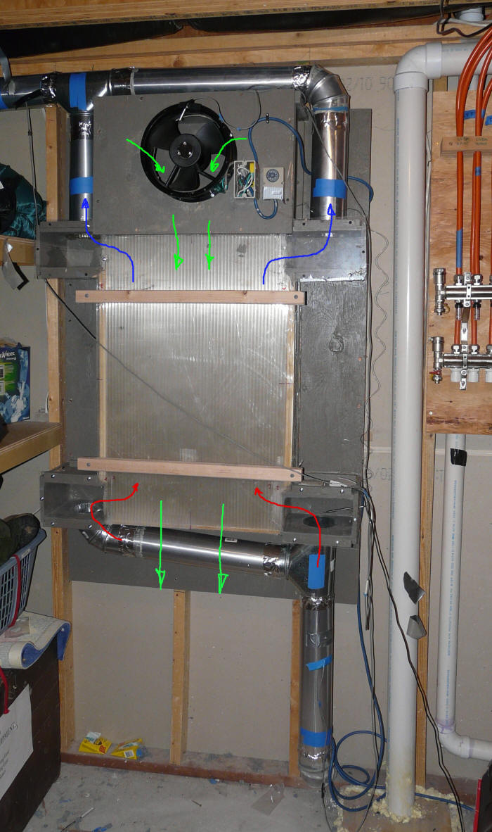
Red arrows show hot dryer air coming into bottom corners of HX.
Blue arrows show cooled dryer air leaving HX at upper corners.
Green arrows show room air entering HX via the fan, flowing straight
down the HX and exiting the bottom (hopefully warmer).
The prototype is made from some scrap, well used, twinwall polycarbonate.
About 5/16ths inch thick.
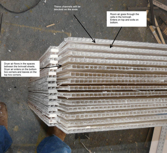
The HX is a stack of 14 of these twinwall sheets. The sheets are spaced
about 1/4 inch away from each other to form 13 channels between each pair of twinwall sheets. The hot exhaust from the dryer will pass through the
passages in the twinwall, and the outside air will pass through the spaces
between the twinwall sheets.

The room air flow through the twinwall itself entering the top and leaving
at the bottom.
The dryer air flows in the 1/4 inch spaces between the twinwall sheets
it enters on the lower left and lower right corners, flows upward
through the channels and exits on the upper right and upper left corners.
The spacers that block the ends of the dryer flow channels have not
been added on this picture yet.
I used this twinwall because it was scrap I had on hand -- it is used
twinwall that was used as packing material for some sheets of new twinwall that
I ordered. I think that Coroplast is a better material to use for a
permanent version of the HX. Likewise the spacers I used to space the
sheets apart are just wood and might not give a very long life if the
environment turns out to be wet with condensing water. Some of the spacers
are made from some left over plastic deck board I had on hand, and these might
be descent choice for spacers on a permanent version.
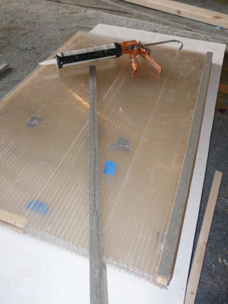
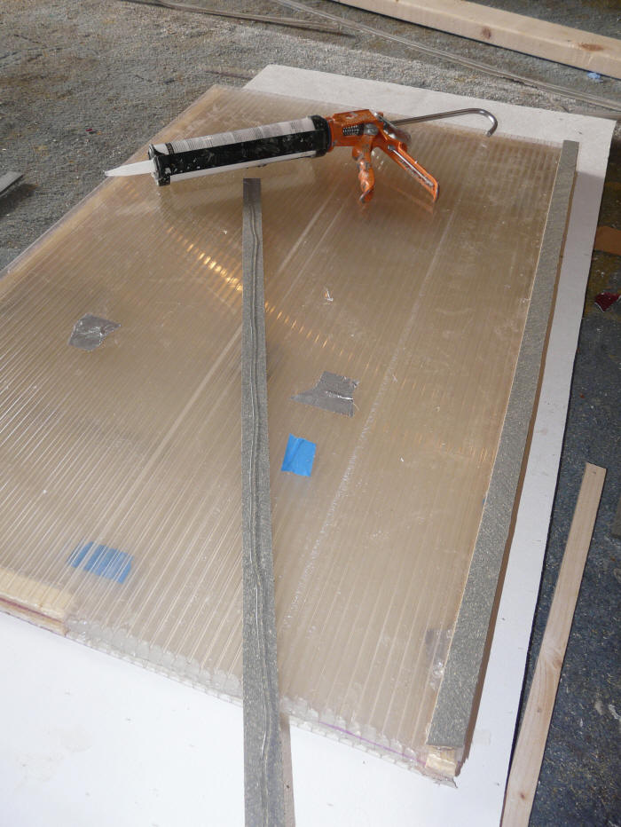
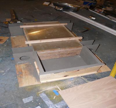
Making the stackup of twinwall layers with
spaces between each layer.
The grey spacer strip with the silicone on it
is about to be placed on the far side.
It is plastic deck wood. |

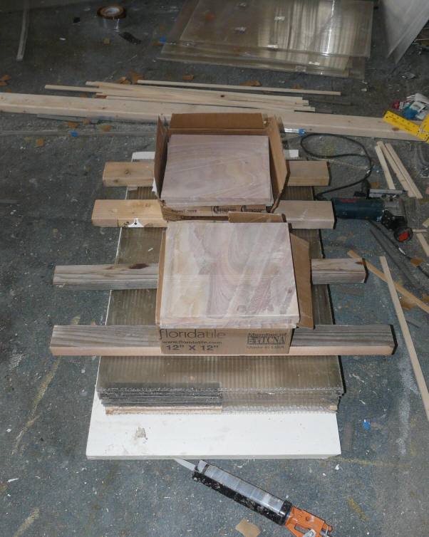
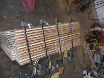
Half of the twinwall stackup -- waiting for the
silicone to set. |
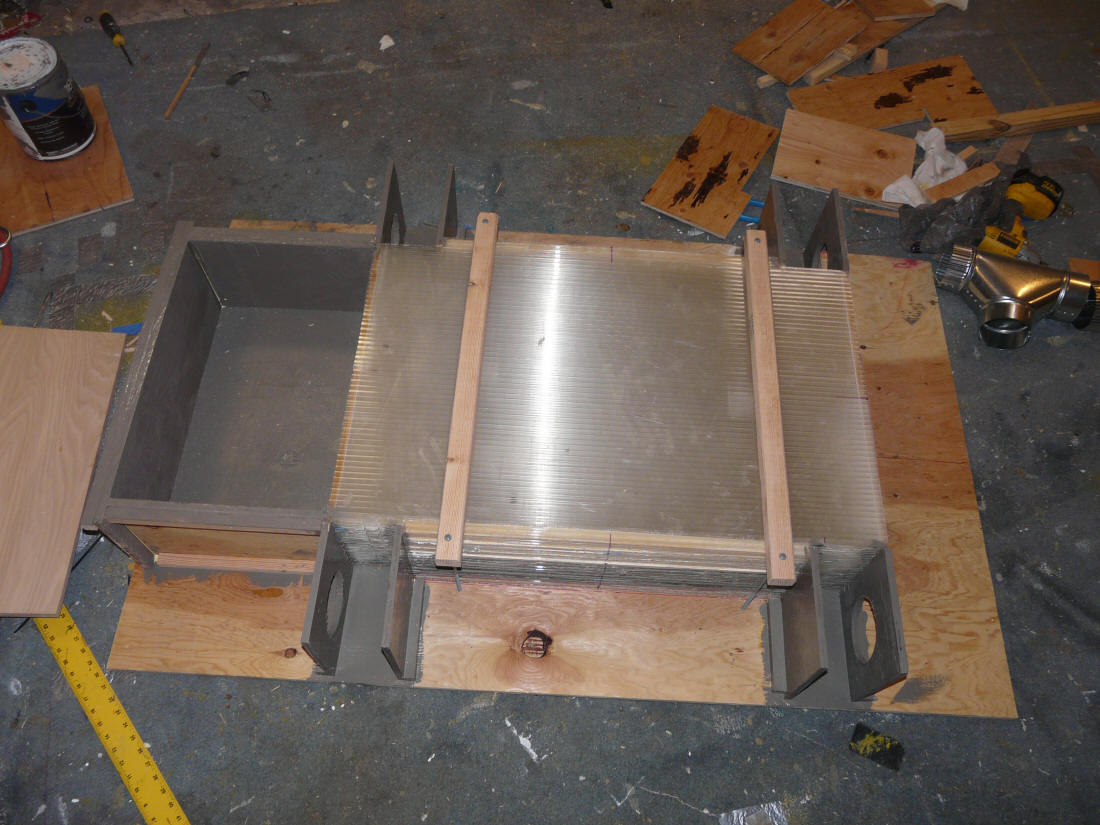
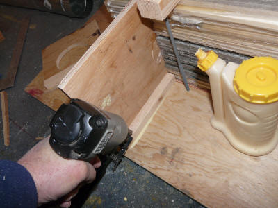
With spacers that block the dryer flow
siliconed in place and curing. |
The 1/4 inch spacers space apart the twinwall sheets to make flow channels
between each pair of twinwall sheets.
Silicone caulk was used for sealing and glue -- it worked quite well with the
polycarbonate twinwall, not sure how well it would do with Corbond?
Until I ran out, I used some left over deck board to rip the spacers from
thinking it would be more waterproof than wood.
Building the stack went pretty fast. It would be helpful to have maybe
two vertical pegs per side coming straight up from the work surface and spaced
to hold the twinwall sheets in exactly the right place to make a square stack.

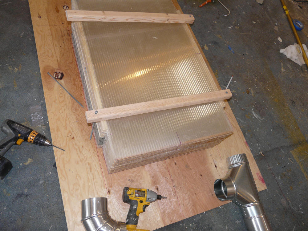
Mounting the twinwall stackup to the plywood
backing board.
In addition to the two hold down 2 by 2's there is
some silicone between the bottom twinwall
sheet and the plywood. |
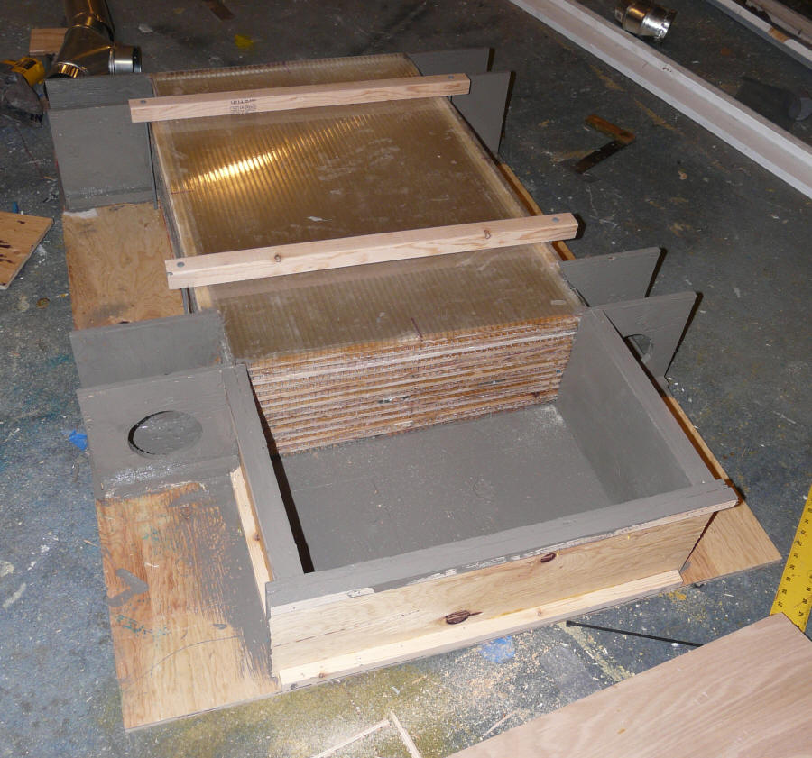
Adding the inlet and outlet boxes.
Silicone caulk was used to seal all the
joints between the HX stack and the
inlet and outlet boxes. |
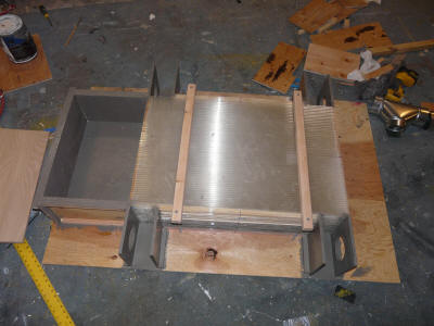
Most of it done.
The room air entry box is at the left -- the fan
that drives the room air will be mounted in the
top cover.
The inlet and outlet boxes at the corners for the
dryer air to enter and leave are mostly done. |
I built about half the stack, and then weighted it until the silicone
set, then continued with the 2nd half.
The final HX block. It is pretty strong -- you don't have to
worry about damaging it when moving it around.
The airpath for the room air is through the cells IN the twinwall sheets.
The room air comes into the top of the HX, flows straight through the HX, and
exits straight out the bottom of the HX.
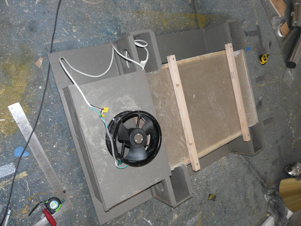
Another view of the mostly completed
heat exchanger. The fan pulls room air
into the larger box at the top, which then flows
down the twnwall sheets. |

With the fan installed on the room air inlet box. |
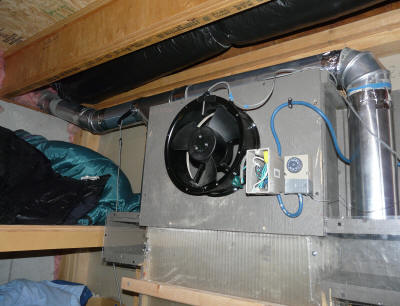
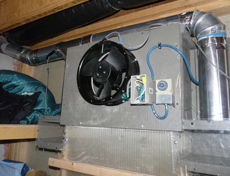
The heat exchanger installed.
The fan is controlled by the thermal switch to
the right of the fan.
The switch sensor is located where it senses when
hot air is coming in from the dryer duct, and
turns the room air fan on. |
The dryer air flows in the spaces between the twinwall sheets and in the
opposite direction (this is a counterflow heat exchanger). The hot
dryer air flows into the two lower corners (see picture above), through the HX,
and then out the two upper corners. The dryer air was channeled through
the spaces between the twinwall sheets to lessen the chance of lint clogging the HX.
Size of each twinwall plate is about 36 inches long about 21 inches wide.
Total heat exchanger area (counting top and bottom of each interior twinwall
sheet) is (20 *36)(13*2)/144 = 130 sqft.
Flow area each way is about (14 plates)(20 inches wide net)(0.25 inch high) =
70 sq inches (about 6 times the area of a dryer duct).
It would have been nice to make the plates longer to allow more complete heat
exchange, but I did not have the material to do it. The heat exchanger in
the Danish paper is about twice as long, but the graph they have showing the
change in efficiency with length indicates that one half as long would still
have achieved about 80% efficiency.
The fan that powers the room air side of the heat exchanger is a
Grainger/Dayton 10 inch fan producing 600 cfm with no pressure resistance.
In this application with the pressure resistance of the heat exchanger it
produces 204 cfm. It only draws 27 watts, so its energy use is negligible
compared to the dryers 5500 watts.
Comments
If you have any thoughts, comments, suggestions, or questions, please use the
comments section on this page... The
results of several dryer test runs with this prototype are also on the same
page.
Gary February 1, 2013