Testing a Prototype Dryer Heat
Recovery Heat Exchanger
There has been a discussion going on in the
Ecorenovator
Forum for a while on figuring out a simple way to recover heat that
the dryer is just exhausting out of the house. I'd been thinking
about doing some kind of dryer heat recovery, and the forum discussion
got me activated.
This page covers the results of the first couple tests of the
prototype dryer heat recovery heat exchanger I did. Construction
of the prototype is shown here.
I'd like to hear any thoughts on how to improve the design or do it
differently. If you have any ideas, please post on this
Ecorenovator thread or in the Comments section
below.
Dryers are very wasteful on the energy front. A lot of the heat
they generate to dry clothes just gets exhausted to the outdoors rather
than actually being used to evaporate water in the clothes. In DOE dryer testing
typical US dryers are about 50 to 60% efficient in terms of how much energy
they use to dry the clothes compared to the minimum energy needed to
evaporate the water.
Its actually worse than this because as the dryer exhausts heat out
of the house, new cold air has to be drawn in somewhere to replace
it the exhausted air, and this new air has to be heated up by your
furnace.
The idea of this first cut prototype is to see if
its feasible to recover a worthwhile amount of the dryer exhaust heat.
Bottom line is that it looks promising, and there are some potential
improvements that could make it a lot better. Any
comments/advice
would be appreciated.
This prototype was made with materials I had on hand -- I'm not recommending
these materials for a heat exchanger that will have a long life. Its more
of a get an idea what the performance is and to identify problems prototype.
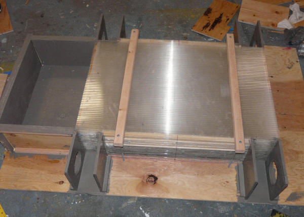
The heat exchanger is a simple stackup of 14 twinwall polycarbonate sheets
that are each spaced apart using spacers at the edges. Its a counterflow
heat exchanger with the dryer air flowing through the spaces between the
twinwall sheets in the up direction and the room air flowing through the
twinwall sheets in the down direction.
Stackup of twinwall sheets with entry and exit air delivery boxes.
The small boxes are inlets and outlets for the dryer air.
The large box on the top is the room air inlet box with the fan removed.
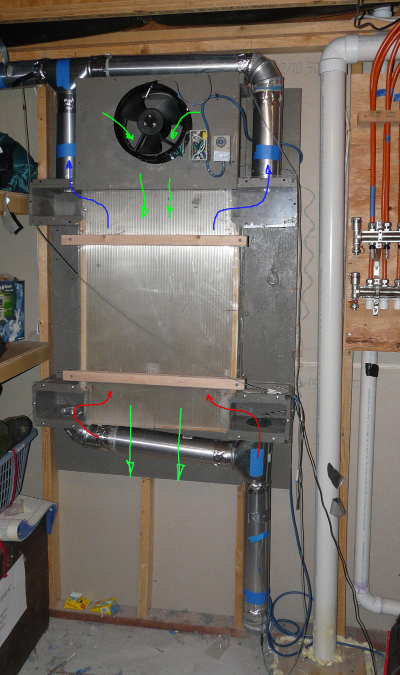
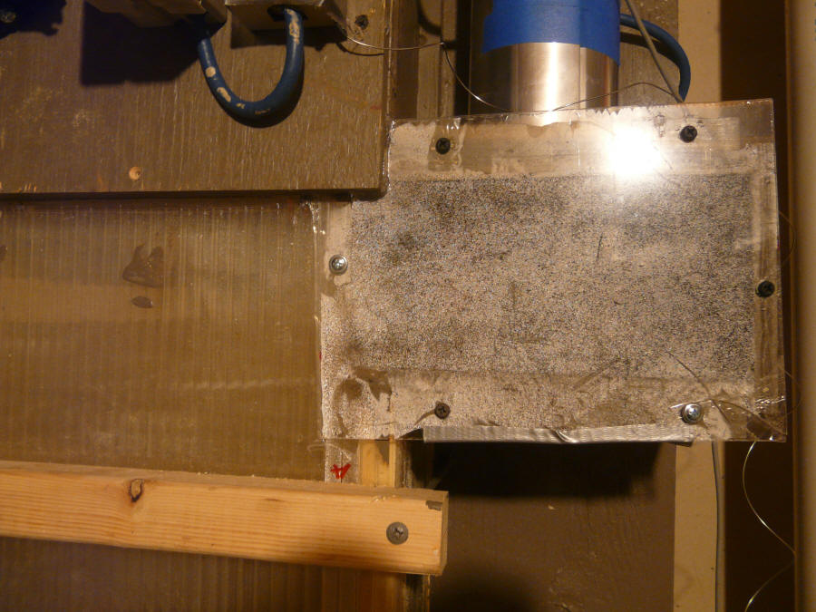
The picture below shows the heat exchanger mounted on the utility room wall
-- the dryer is just on the other side of the wall. The exhaust duct from
the dryer comes in at floor level and goes up to the lower right corner of the
heat exchanger. The duct leaving at the upper left goes outside.
Red arrows -- show hot dryer air coming into bottom corners of HX.
Blue arrows -- show cooled dryer air leaving HX at upper corners.
Green arrows -- show room air entering HX via the fan, flowing straight
down the HX and exiting the bottom (hopefully warmer).
The fan is turned on by the capillary switch mounted to the right of the fan.
The sensor for the switch is the tube you can see in the lower right dryer air
entry box with the clear cover.
Running a Test Load Through the Dryer With Heat
Recovery Heat Exchanger
These are the details on running one of the test loads through the dryer,
it covers the results and also asks some questions, and passes on some thoughts
on better designs.
Dryer is a Maytag Neptune -- approximately 2001.
Settings were: Sensor Dry = on, Dryness = "Very
Dry", Temperature = "Regular" (the highest temperature setting).
I realize the "Very Dry" setting uses more energy, but on the other hand some
of the items were still a bit damp at the end.
Weight of Water in the Load
The dryer load was several towels, a bath matt, and some odds and ends -- a
good sized load.
Wet weight = 17.63 lbs
Dry weight = 9.75 lbs.
Water weight removed = 17.63 - 9.75 = 7.88 lbs
The energy required to evaporate 7.88 lbs of water is
(970 BTU/lb)(7.88 lbs) = 7644 BTU or 2.24 KWH
where 970 BTU/lb is the heat of vaporization for water -- the energy required to
evaporate 1lb of water.
So, this is the minimum
energy required to evaporate the water this dryer load.
Energy Used and Energy Recovered
This section covers all the energy used to run the dryer and to heat the cold
air that the dryer pulls into the house, and also covers the heat recovered by
the new heat exchanger -- and discusses some improvements.
The section after this gives a summary of energy use for a regular dryer and
the dryer with heat exchanger and a further improved heat exchanger.
Electrical Energy Used
The dryer fan and dryer tumbler motor use about 260 watts and runs for the full cycle using about 0.26
KWH.
The heating element uses about 5150 watts and ran for most of the drying
cycle.
Total power usage was 4.26 KWH for this load.
This was recorded on a TED energy monitor that was just hooked up to the
dryer circuit.
HVAC Energy Used
As the dryer air is exhausted outside, new air is pulled into the house to
replace the exhausted air. If its cold or hot outside, then this air
must be conditioned by your furnace in the winter or your AC in the summer.
So, this take more energy.
For this load, the outside temperature was 20F, and the amount of heat to
condition that air is:
So, in this case, it takes half as much energy for the
furnace to heat the air that the dryer pulls into the house as it took for the
dryer to dry the clothes.
Total Energy Used
So, the total energy used is 4.26 KWH of electrical energy used by dryer plus
2.35 KWH of propane for the furnace.
A total of 6.61 KWH for this load.
Energy Recovered by Heat Exchanger
Heat Exchanger Parameters
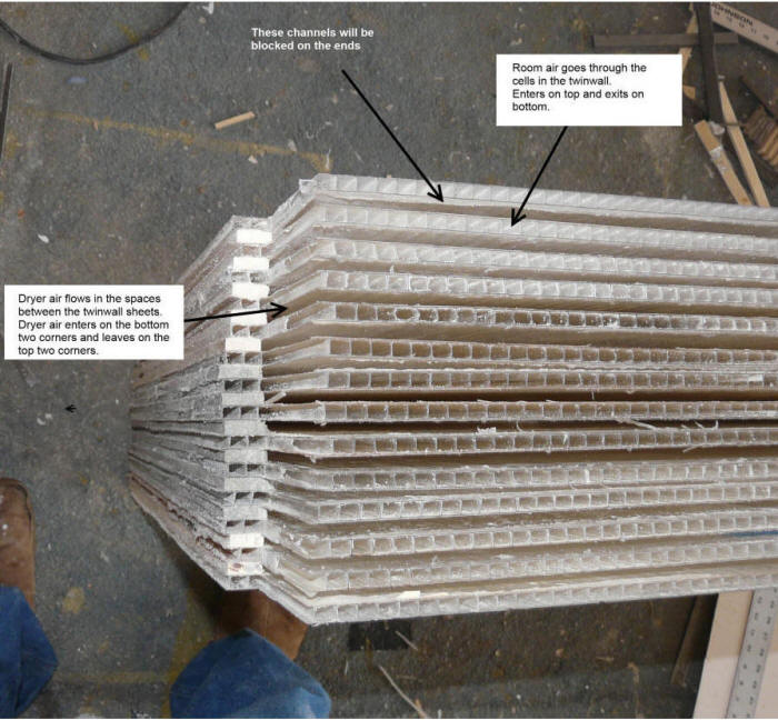
The airpath for the room air is through the cells in the twinwall sheets.
The room air comes into the top of the HX, flows straight through the HX, and
exits straight out the bottom of the HX.
The dryer air flows in the spaces between the twinwall sheets and in the
opposite direction (this is a counter flow heat exchanger). The hot
dryer air flows into the two lower corners (see picture above), through the HX,
and then out the two upper corners. The dryer air was channeled through
the spaces between the twinwall to lessen the chance of lint clogging the HX
(more on lint below).
Size of each twinwall plate is about 36 inches long by about 21 inches wide
(about 20 inches net inside).
Total heat exchanger area (counting top and bottom of each interior twinwall
sheet) is (20 *36)(13*2)/144 = 130 sqft.
Flow area each way is about (14 plates)(20 inches wide net)(0.25 inch high) =
70 sq inches (about 6 times the area of a dryer duct).
It would have been nice to make the plates longer to allow more complete heat
exchange, but I did not have the material to do it. The heat exchanger in
the Danish paper is about twice as long, but the graph they have showing the
change in efficiency with length indicates that one half as long would still
have achieved about 80% efficiency.
Spacers were added between the sheets of twinwall on the end to block the
flow of dryer air into the flow path for the room air -- the picture was taken
before these were installed.
Room air side of HX:
The room air side flow
passages are 1/4 inch tall, and about 5/16 inch wide. There are 14 layers
of twinwall that the room air goes through, and each is 20 net inches wide, and has
about 64 of the 5/16 ths wide flow passages. Total area is 70 sq inches
(0.486 sf).
For the test, a short outlet duct was added to the bottom
of the heat exchanger that was the full size of the HX -- this was to allow a
more accurate air velocity to be measured.
Outlet duct area 7.75 inches by 21.5 inches is 166.6 sq
inhes or 1.16 sqft
Velocity was measured with a Kestrel wind meter at 9
locations in the exit duct on a grid. An Alnor Velometer was also
used as a check on velocities.
Average outlet duct velocity = 176.6 fpm
Flow rate for room air through the HX = (176.6 ft/min)(1.16
ft^2) = 205 cfm
The fan that drives the room air side is a
Grainger/Dayton 10 inch fan. It only draws 27 watts, and its power
consumption is pretty much ignored in the performance numbers below (27
watt-hours out of 6000+ watt-hours used by the dryer).
Dryer side of HX:
The dryer side flow
passages are 1/4 inch tall, and about 20 inches wide. There are 13 of the
dryer flow layers between the 14 sheets
of twinwall. Total area for dryer air is (13)(20)(0.25) = 65 sq inches
(0.45 sf). This is about 5 times the area of the 4 inch dryer duct.
The 4 inch dryer duct has an area of 0.087 sf.
Air velocity in dryer duct was measured with an Alnor
Velometer and a Kestrel
wind meter in the straight section of duct between the floor and point just
below HX where the duct splits in two.
Inlet duct velocity = 1630 fpm
Flow rate for dryer air through the HX = (1630 ft/min)(0.087
ft^2) = 141.8 cfm
The velocity of the dryer air in the actual HX is
(141.8 ft^3/min) / (0.45 ft^2) = 315 fpm or 3.6 mph (is this enough
carry droplets of condensation along in the flow?)
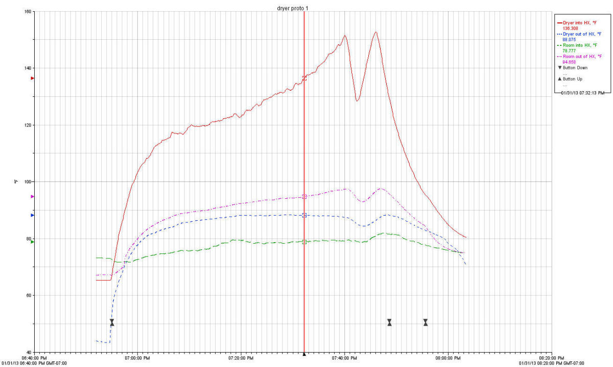
Heat Exchanger Performance
The dryer starts at 6:55 PM (the first set of triangles) and the heater
element runs continuously for the first 45 minutes until 7:40. At this
point the heater cycles off for a few minutes to keep the temperatures from
getting too high, and then comes back on again for a few minutes before the
dryer "cool down" starts at 7:48, which lasts until the dryer turns off at 7:55
pm.
Maximum temperature of the dryer exhaust is 153F.
The top red curve is the temperature of the air leaving the dryer, and this
gets cooled down to the temperature of the blue dash curve by the time it leaves
the HX. The green dash curve is the temperature of the room air entering
the HX, and it gets heated up to the purple dash-dot curve in the HX.
So, looking at time that that is about average (where the vertical red
line is), the dryer flow comes into the HX at 136F, and leaves at 88F for a
48 F drop in temperature. And, the room air comes into the HX at 79F
and leaves at 95F for a 16 F rise.
The dryer air exits the HX at 88F with a room temperature of 79F, so it
taking the dryer air to within 9 F of room temperature.
Part of the reason that the rise in room air is not as large as the drop in
dryer air temperature is that the room side air flow rate is about 44% higher.
Heat Taken Out of Dryer Air:
Rate of Heat Removal = (Temp drop)(flow
rate)(density)(specific heat of air)
If the heat exchanger were perfect, the 136F dryer air
would be cooled by 57.5F (down to room temp) rather than the actual drop of
48.2F, so I guess you could say that on a temperature basis is its about
48.2/57.5 = 84% efficient at this point in the cylce-- not so bad for a made out of scrap HX :)
The 0.065 lb/cf for air density is lower than the usual
0.075 lb/cf because of our altitude.
Heat Gained by the Room Air:
Rate of Heat Gain = (Temp drop)(flow
rate)(density)(specific heat of air)
It seems like the heat taken out of the dryer air stream should equal the
heat gained by the room air stream -- they are the flows on the two sides of the
same heat exchanger.
Just guessing at why they are so different: 1) There is some air leakage from
the dryer side of the heat exchanger to the room, 2) The heat exchanger surfaces
get
warm and lose heat to the room directly from its outer surface, 3) the dryer
duct into the HX passes right through the room air exhaust from the heat exchanger for
about 2 ft, so the hot duct loses some heat to the room air before it gets to
the HX, 4) if some of the water vapor in the dryer exhaust is being converted to
water, that removes heat from the dryer exhaust side of the HX without
recovering it to the room air side? 5) measuring the velocity of each of the two
streams is always challenge and there is bound to be some error there.
The first three reasons listed above mean that more heat is actually being
recovered than the 3031 BTU/hr -- hard to say how much.
The HX outlet duct velocity is about 20% less than the HX inlet duct
velocity, so the first reason in the list above is probably an important one.
For the purposes of the claimed heat recovery that gets to the room, I'm
going to say its half way between the 1.87 KWH and the 0.89 KWH, or 1.4 KWH.
Note that on some of the other tests, heat removed from dryer stream is
closer to the heat added to room air stream, but there is always a significant
difference.
Any ideas on what might be accounting for this pretty large difference?
One thing that would make the HX more efficient is a good steady source of
cool air for input. The heat exchanger is in a utility room that started
at 72 F, and got heated to 80 F by the dryer heat exchanger -- it would work
better if there was a steady source of (say) 65F air for the HX input.
This would cool the dryer air to a lower temperature, extracting more heat from
it.
Other Design Issues
These were some other issues that the prototype was built to explore.
Flow Resistance of Heat Exchanger
One concern was that the heat exchanger would add too much air resistance to
the dryer flow.
The dryer duct velocity and flow rate with a very short duct was 1850 fpm and
161 cfm.
Adding the heat exchanger and about 10 ft of ducting plus the flipper vane on
the house wall brings the flow rate and velocity down to 1630 fpm and 142 cfm.
This seem fine to me and is right in the range of flow velocities mentioned
as typical in the dryer testing reference.
So, I think its fair to say that at least this heat exchanger does not add
too much flow resistance.
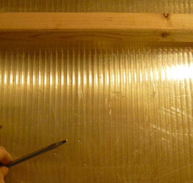
Not a Lot of Liquid Water Visible
I expected to see water in the heat exchanger during the drying process as
the high humidity dryer exhaust air was cooled down below its dew point in the
heat exchanger and water condensed out. One of the reasons for building the
prototype was to see how much water and where it went and what might be done to
make the heat exchanger life OK with the water.
From near the start of test to about the beginning of the dryer "cool down"
period, there was some condensation visible on the upper two windows and in
about the upper 2/3rds of the twinwall. Most of this was very small
(like a fogged windshield) but, there were a few droplets that got started and
were making their way down the twinwall. I did not see any moisture make
it to the bottom of the HX.
Condensation upper dryer air outlet box and
inside the top part of the twinwall stackup.
A few drops of water making there
way down the inside of the HX.
As soon as the dryer cool down period started, all signs of moisture went
away.
Using this dew point calculator, if you take an the middle of the dryer run
with dryer exhaust at 130F, and assume a relative humidity of 80% for the dryer
air, then the dew point is 123F.
Since the dryer air at this time is being cooled to about 88F (which is well
below the dew point), it seems like there should be water condensing out -- lots
of water?
Perhaps the condensing water is being swept out in the air stream. The
velocity of the dryer air moving up the heat exchanger is 3.6 mph.
Because of the construction with twinwall, I can see into the heat exchanger
and can see the wood fillers that block off the dryer heat exchanger channels at
the end -- no visible water.
Any thoughts on where the nearly one gallon of water is going?
From a making life easier on the heat exchanger point of view, the absence of water is nice
in that it is easier to build one that would have a good life, but it also means
that the heat used to evaporate the water is not being recovered.
See the Improvements section below.
Not Much Lint Either
I intentionally did not put any extra lint filter in the dryer outlet duct
just to see how bad it would be and whether there would be any tendency to plug
up the heat exchanger passages (which are pretty large).
After 4 loads, I don't see any sign of lint anywhere in the heat exchanger or
in the entry/exit plenums.
Maybe lint takes a while to build up, or some clothes are more lint producers
than others and we have not gotten to them, but no lint so far. There is,
of course, a lint screen on the dryer that gets cleaned before each load, and it
does accumulate lint.
If we go ahead with a "production" version, I do plan to add an easy change
lint filter.
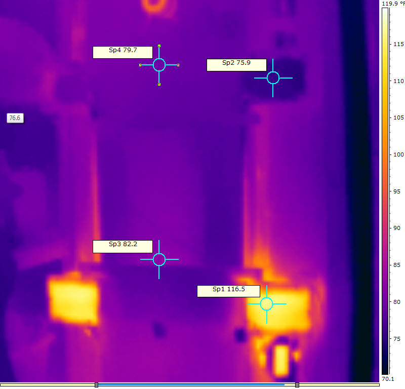
Thermal Images
Bright spots on the bottom left and right are the boxes where the hot dryer
air enters the HX -- around 116F.
Dark spots to right and left near the top are the boxes where the cooled
dryer air leaves the HX -- around 76F.
The hot circle right at the top is the hub of the fan that blows room air
through the HX.
What Could be Improved?
Stage 1:
The heat exchanger as it is saves about 32% on the total energy used by the
dryer electricity use, and this seems worthwhile. It could be made better
by:
- Pulling air from a cool place and sending the warmed
air to another room so that the HX has a continuous supply of cool air.
This does add some complication -- maybe just ducting the outlet air to a place
that could use it would be enough?
- Making the HX longer to improve the efficiency (perhaps
as much as 10%).
- Try to work out a way to recover liquid water from the
dryer airstream to gain back the heat that went into vaporizing it.
- Building it tighter with less leakage.
Although a bit of leakage from the dryer flow into the room does recover some
added heat :)
- More durable and water proof materials.
Stage 2:
If the heat exchanger design could be changed such that it condenses out most
of the water in the dryer exhaust stream, it seems like lots of benefits would
result:
If the liquid water that the HX condenses could be collected and put
down the drain, then you are recovering the heat that went into vaporizing
this water in the dryer. For example if 70% of the 7.88 lbs of water
in the clothes could be condensed out, then (7.88)(0.7)(970 BTU/lb) = 5350
BTU or 1.6 KWH could be recovered.
If most of the water in the dryer exhaust stream could be condensed out,
than electric dryers could likely be vented inside the house without
concerns about excess humidity. This would require an effective lint
filter, but this certainly is doable. This would save your HVAC system
the energy it uses to heat or cool the air that the dryer pulls into the
house. On this test load, this would be a saving of 8030 BTU or 2.35
KWH -- A major win.
These two additional savings are worth a good deal more than the heat
recovery that the heat exchanger achieves now.
What else might be done??? -- got any ideas?
Energy Summary -- Various Schemes
In these graphs:
Electricity-- is the total electricity used by the dryer
HVAC -- is the energy used by your furnace to heat the outside air that the
dryer pulls in
Heat Recovery -- is the heat recovered from the dryer exhaust by our heat
exchanger
Condensing -- is the energy recovered by condensing water in the dryer exhaust
stream
Standard Dryer -- vent outside, no heat recovery (business as usual for most
homes):
6.65 KWH total
Standard Dryer with Heat Recovery Heat Exchanger
5.35 KWH total
This is a 32% saving based on dryer electricity, and 21% based on total energy.
This is the configuration used for this test.
Standard Dryer with Water Removal via Heat Recovery HX and Inside Venting
1.3 KWH total
This is a 126% saving based on dryer electricity use, and an 80% based on total
energy.