Off The Shelf Solar DHW -- Cheap and
Easy DIY Solar Water Heating
This project is a go at an inexpensive DIY solar water heating system
that is also easy to build. While the system is
inexpensive and easy to build its not cheap in the sense of low quality
-- I believe that its life and performance will be similar to commercial
systems.
Our $1K DIY Solar Water Heating system
has been a popular project and has been built successfully by a lot of
people. It is about one eighth the cost of a typical installed commercial solar water
heating system, and that's nice. But, it requires you
to build the collector and the solar heat storage tank yourself. While
building the tank and collector are fun projects, it does take some time and
is a bit more
that some people want to tackle.
This new system is aimed at using all off the
shelf components while still keeping the cost down. So, the
project becomes one of just mounting the components and hooking them
together. Since the design is very simple, the hooking the pieces
together is a pretty straight forward job.
I'm in the middle of building the prototype and would like to hear any
comments or ideas for improving the design that you might have.
comments....
Think of it as an open source solar water heating project.
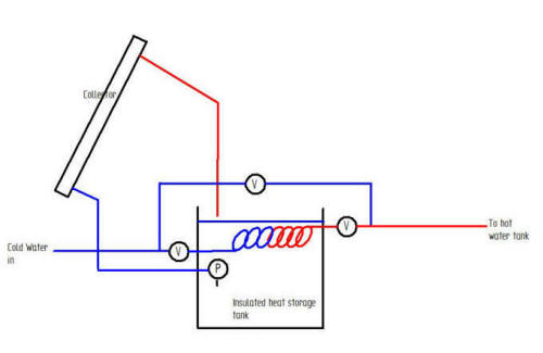
The system is a simple drain back design that uses a large, non-pressurized
tank for both the solar heat storage and as the collector drain back tank.
The pump (P) pumps water from the bottom of the large storage tank, up through
the collector to be heated, and then back to the top of the storage tank.
Incoming cold water from the street passes through the large pipe coil immersed
in the storage tank and is heated by the hot storage tank water before it gets
to your existing hot water tank. The three valves provide for bypassing
and isolating the solar tank for maintenance. There is a controller (not
shown in the diagram) that turns the pump on only when the collector is hotter
than the storage tank water. Your existing hot water tank provides
backup water heating when there is not enough solar heating. Freeze
protection is provided by the fact that the water in the collector loop drains
back to the tank when the pump turns off
The system design is actually the same as the $1K Solar Water Heater. The
difference is that all of the components for this system (tank, collector, pump,
and controller) are off the shelf items that you just buy. You just
mount the components and hook them up.
Components:
Collector -- The system uses unglazed plastic matt style pool heating
collectors.
Tank -- The solar storage and drain back tank is the SofTank from American Solar
Technics.
Controller -- The controller is the SR208C sold by Sun-Pump.com.
Pump -- The pump on the prototype is the Grundfos 15-58 3 speed HVAC circulator
pump.
Other than some plumbing, valves and a little wire, that is the whole system.
See the discussion below for the pros and cons of these component choices.
The Prototype
I'm building the prototype on my
Solar Shed using the roof above the existing water
heating collectors. The prototype is just being built to see how the
system works -- I plan to take it down after getting (at most) a years worth of
performance. Since the system is not hooked up to our house, the daily hot
water demand will be simulated. So, the location and fit and
finish look a bit odd just because its not a permanent addition to the house.
Note that this is a prototype and looking nice is not a priority --
that's easy to take care of once things work right.
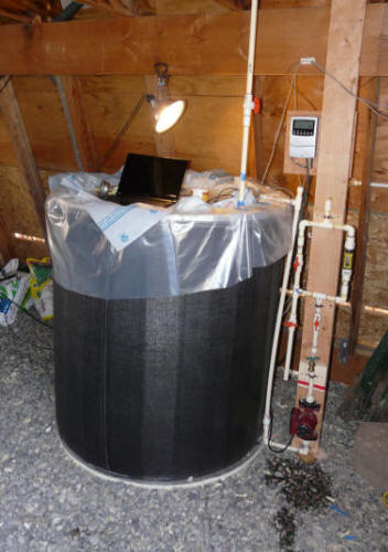
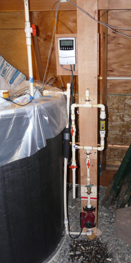
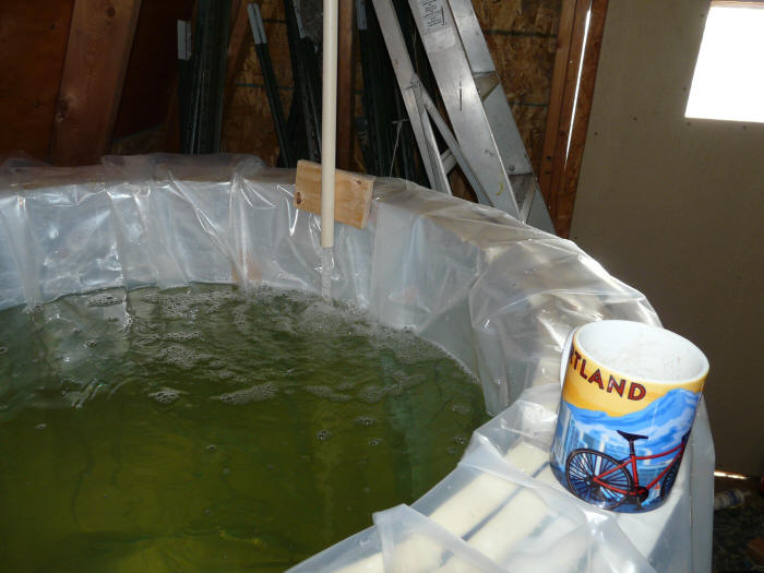
The prototype tank, controller and pump before finishing touches.
Setup for logging performance.
Collector
The collector is a Gull Industries 4 by 10 ft unglazed pool heating collector.
There are tradeoffs in using this unglazed collector as opposed to the glazed
collectors that are normally employed in solar water heating systems.
The pros and cons (I think) for these unglazed matt style collectors are:
Pros:
Low cost (as little as1/10th the cost per square foot of glazed commercial
collectors)
Good performance in three seasons.
Easy to install (light weight with simple mounting)
It is cheap to provide an excess of collector area to help make up for
poor cold weather performance.
Qualifies for most tax credit and rebate programs because most of these
collectors are SRCC certified.
Light weight and rolls up into a cylinder for easy and cheap shipping.
Cons:
Poor cold weather performance (see below for possible partial remedy)
Shorter life (15 to 20 years?) -- but, easy to replace.
Will they work? (temperatures, drain back, ...)
There is a potential for improving winter performance that is discussed
below.
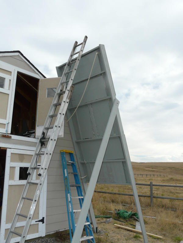
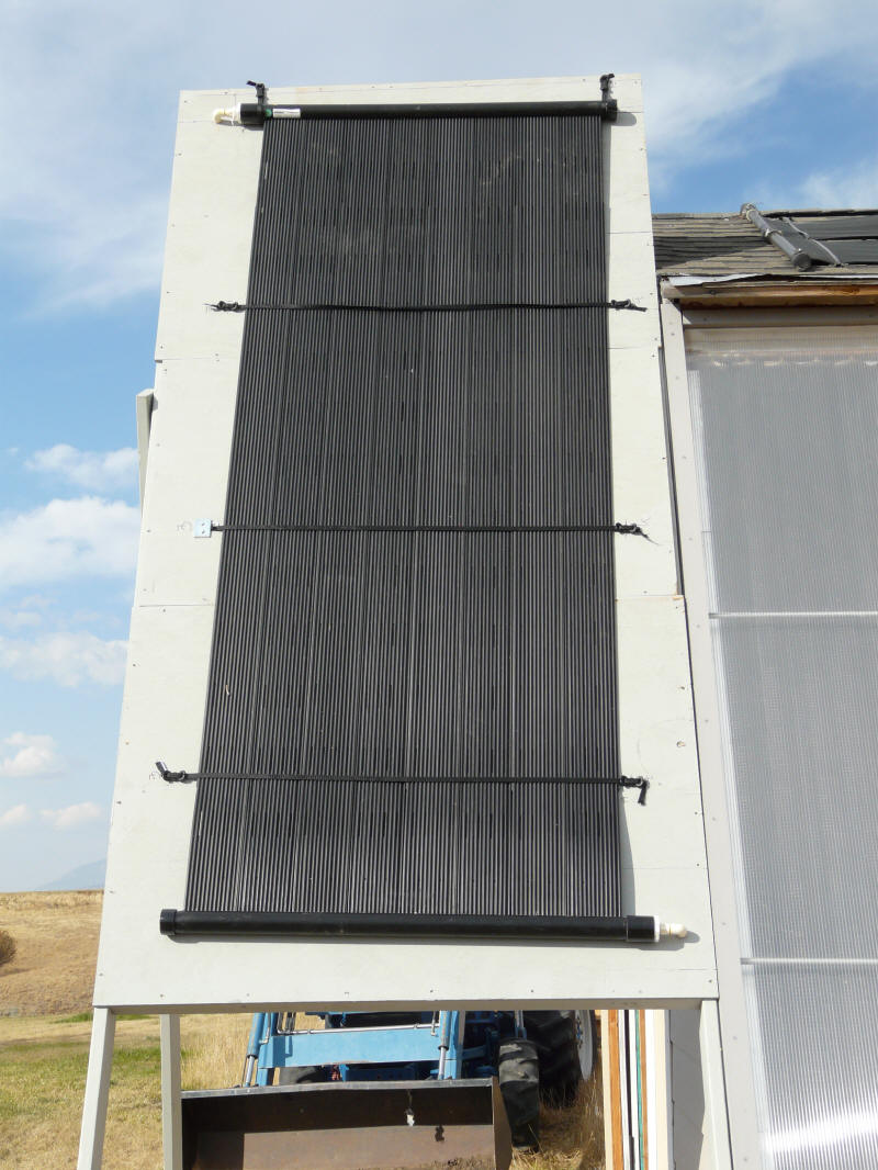
In order to have a place to mount the collector for this prototype, I built a
temporary ground mount next to my Solar Shed. The tank, pump, and
controller are located in the Solar Shed. The collector is mounted high
enough off the ground so that it drains back into the storage tank in the shed.
The temporary mounting structure for the collector.
The collector is mounted facing south and at a steep tilt
angle (about 70 degrees). The idea of the steep tilt angle is to improved
late fall, winter, and early spring performance, and also to reduce overheating
potential in the summer. I might have chosen a somewhat less steep tilt angle, but
the 70 degrees matches Solar Shed structure, and performance does not change
rapidly with tilt angle, so the difference between (say) 60 degrees and 70
degrees is quite small.
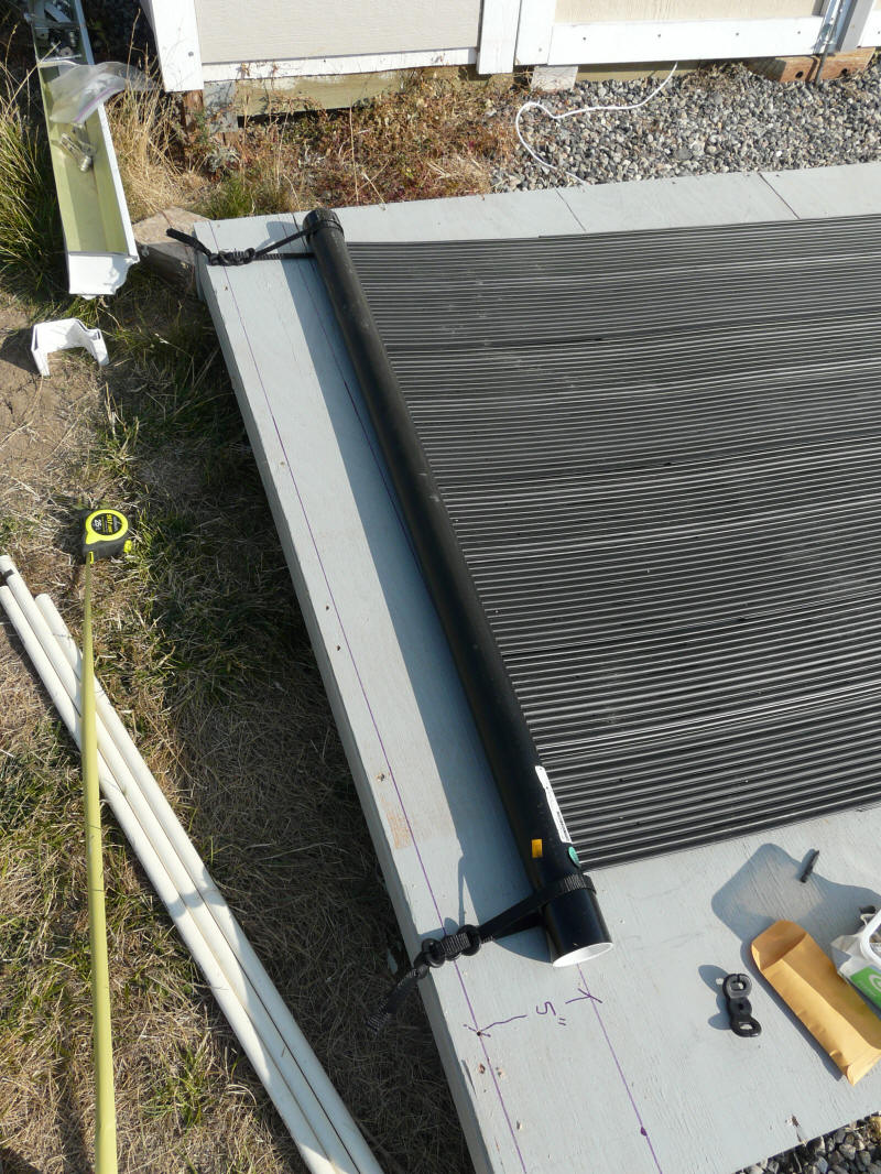
Since the it was easy to do, I mounted the collector on
the ground before tipping the ground mount up into position. But,
its a relatively easy collector to mount on an existing roof -- far easier than
heavy glazed collectors. If mounting on a roof, the two upper manifold
support straps can be installed, and then the upper manifold is just hooked into
the straps. With the collector hanging from the upper straps, the cross
straps are easy to install over the collector. The about 20 lb weight of
the collector makes it relatively easy to maneuver into place.
The collector is basically hung from its top manifold.
The manifold is attached to the roof surface using two supplied straps and
anchors that screw into the roof and are sealed with roofing cement.
Mounting the top manifold of the collector
to the "roof".
Closer view of the mounting strap that
secures the top manifold to the roof.
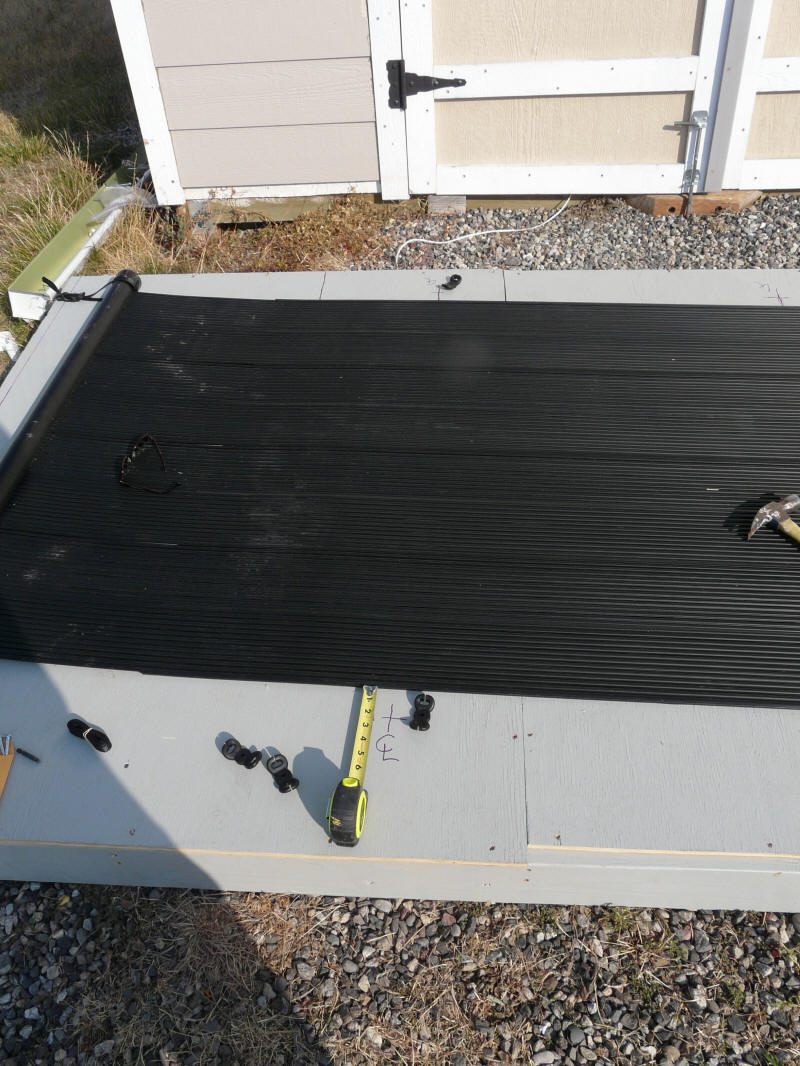
Once the collector manifold is strapped down
the three hold down straps that go
across the collector are installed.
The lowest of the three hold down
straps in position. Note that the Lower manifold
is not secured down, so the collector is
free to expand and contract vertically.
The collector and mount board ready to tip
up into place.
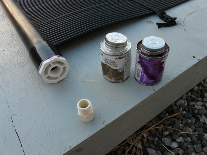
The 2 inch manifolds are adapted to the
3/4 inch CPVC collector supply and return
lines using standard 2 inch PVC fittings
that are solvent welded.
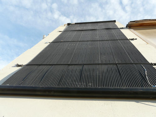
The collector in position. The supply line comes into the lower right
corner, and the return line leaves
from the upper left corner. During drain back, all of the water in the
collector and plumbing drains back
to the storage tank via the supply line. The collector is tilted a little
bit down toward the supply corner so
that all of the water will drain out of it. This collector drains with
gusto :)
In version 1 of this project, I used horizontally oriented collectors on the
upper (low pitch) roof of the solar shed. I like this new vertical
collector approach better because:
The collectors are supported more securely and hang better -- there is
no tendency to develop wrinkles or folds.
They appear to me to be more likely to survive strong winds.
They drain back to the tank fully and completely when the pump shuts
down for freeze protection.
I believe that it will be easier to experiment with "leaky" glazing (see
below) with these collectors.
These particular collectors come in 4 by 8, 4 by 10 (which I used), and 4 by
12 ft. The 4 by 12 ft collector gives you 48 sqft in a single collector.
In any case, if more collector area is needed, then a pair of collectors can be
installed side by side with the manifolds connected together.
I'm using 3/4 inch CPVC pipe for the supply and return lines -- PEX or copper
could also be used. While larger diameter
pipes are commonly used in pool heating systems, the 3/4 inch CPVC (or PEX)
provides plenty of area for the flow rates needed for 1 or 2 collectors in a
solar water heating system. I adapted the 2 inch manifolds down to the 3/4
inch CPVC using standard PVC and CPVC fittings that are available at the
hardware. While it is common practice to use rubber hose to couple
the collector manifolds to the system plumbing, I just solvent welded the PVC
fittings to the polypropylene manifolds. This (so far) has been fine and
the fittings appear to be very secure with no leaks, but I need to do more
looking into whether this is will hold up for the long term. In any case,
the rubber hose attachments are easy to use if the solvent welding does not work
out.
The 2 inch PVC fittings used to adapt the collector manifolds down to 3/4
inch are certainly at the top of their temperature capability (about 140F), but
I think they will probably be OK in this low pressure, moderate temperature
application. CPVC fittings could probably be ordered if proves to be a
problem.
For this prototype, since I was not going through a roof surface, I did not
worry about making the penetrations of the CPVC through the "roof" water tight,
but the method shown on this page using small, low
profile silicone rubber
roof jack would work fine. The 2 inch diameter manifold gets the
3/4 inch up off the roof enough that there is room for an elbow to make the turn
directly down to the roof surface and through the low profile roof jack.
The vertically oriented collector appears to be very secure and hangs nice a
straight with no wrinkles. All the joints went together easily with no leaks.
Drain Back:
The drain back on this collector is rapid and appears to be very complete.
The combination of the larger flow passages and the vertical orientation make me
feel more certain of complete drain back than with the version 1 horizontal
collectors.
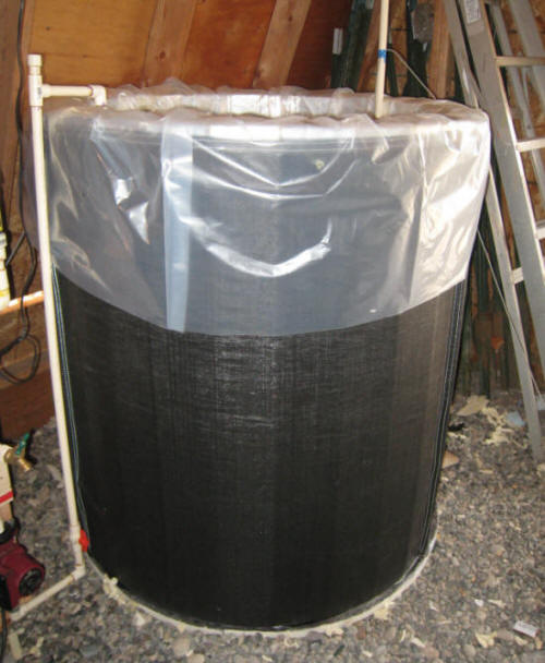
Tank
The tank for the system is the Softank kit from American Solartechnics.
Tom Gocze, who runs the company, has a long history in the solar industry, and
has been making tanks for many years. He also shares a strong desire to
see the price of solar water heating systems come down dramatically.
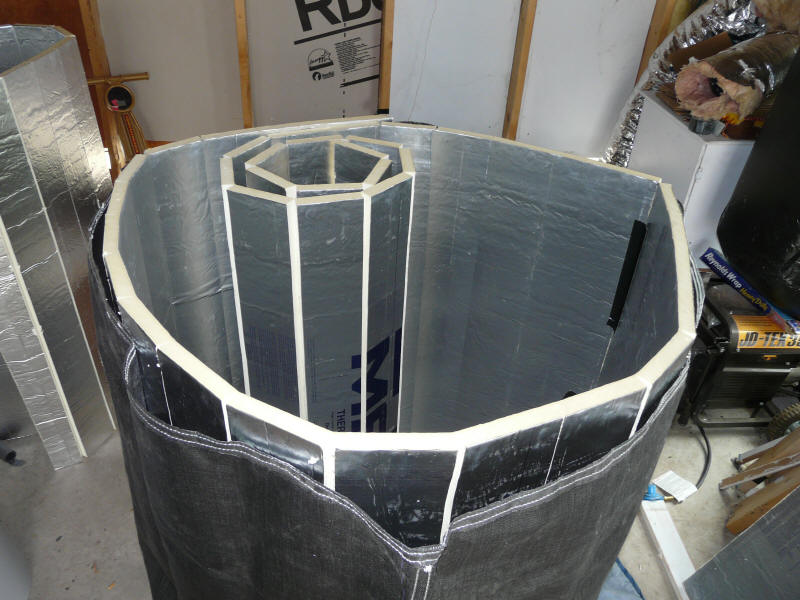
The tank is a unique design. It uses a woven fabric cylindrical outer
layer that takes the pressure loads, 4 layers of 1 inch polyioscyanurate
insulation for about R26 go inside the outer layer. The inner liner
provides the water containment. Cost is $219 plus about $150 worth of
insulation board that you buy locally.
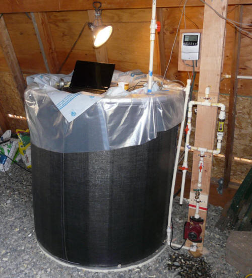
Tank without before lid and finishing touches.
Pro:
On a dollars per gallon basis, the tank is very inexpensive -- about
1/10th what commercial metal tanks cost
The tank ships in a small and lightweight package
Con:
The life may be less than a top of the line stainless solar storage tank
(or not?).
There must be other cons, but I'm hard pressed to think of any? Its
not shiny?
The tank may not be as cool to look at as a $3000 stainless steel solar tank,
but it appears to be a good practical design that provides a lot of storage
volume for a low price.
The tank is an interesting study in load paths and efficient material use. The outer
cylindrical sleeve is
strong in hoop tension and the water pressure (which is substantial) loads it in
tension, so that works nicely. But, if you filled the sleeve with water,
and pushed downward on an edge, the tank would easily be collapsed. Its
the insulation board that is compressed between the inner liner and outer sleeve
that stiffens the tank vertically. Its surprisingly stable -- I can sit on
the edge without collapsing it. Its hard to imagine a tank that would be
more efficient in material use or load paths.
In this version of the prototype, I am only using 132 gallons of about 175 gallon
capacity, so the tank is about 3/4 full. The 132 gallons gives about 3.3
gallons per sqft of collector, which is plenty.
The 175 gallons would support at least 80 sf of collector for larger systems.
I believe that the Softank design may have changed a bit since I bought mine,
so you might want to check with Tom for the latest.
I'd like to thank Tom for a lot of good ideas for this project.
The tank comes with a good assembly manual, but here is a quick overview of
how it goes together.
Bottom and Lid:
The bottom and lid are circles of different sizes cut from 2 inch rigid
polyiso insulation board.
Cutting the bottom out with an electric jig saw.
A keyhole type handsaw would also work fine.
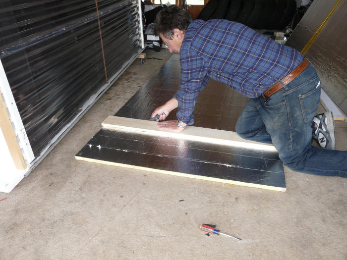
Cutting insulation for sides:
The insulation board for the tank sides must be scored and snapped so that it
can be bent to the radius of the tank sleeve.
Scoring the insulation board at about
six inch intervals.
Snapping the insulation board over a 2 by 4. I later
found that just snapping it over a knee sheetrock style
was faster and worked fine.
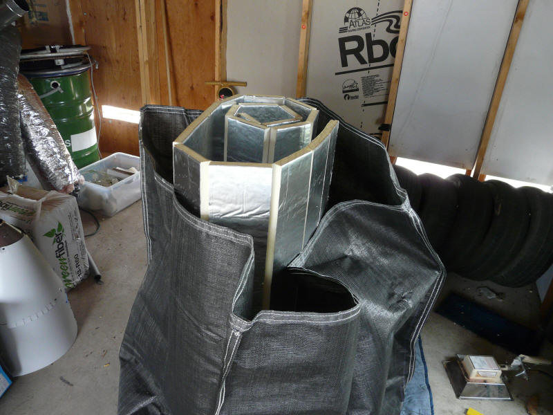
Placing first insulation board in sleeve
Adding 2nd insulation board -- work things around
in a circle keeping as tight to the sleeve as possible.
All 4 layers of insulation board in place and
pushed out against the sleeve.
Placing Lining:
The tank holds about 1500 lbs of water, so it needs a good flat base. I
leveled out the gravel floor, and then cut a rigid foam board insulation base
for the tank to sit on.
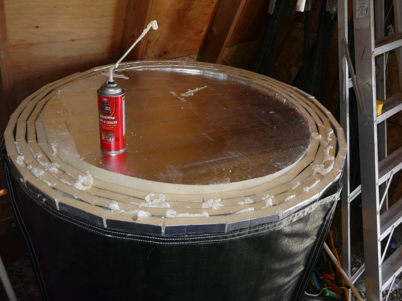
Before installing the lining, I put the lid circle in place to push the side
insulation out against the sleeve, and then filled the cracks and gaps with
Great Stuff. This is probably not necessary, but easy to do.
Leveled out the gravel floor, and added a
piece of rigid foam board under the tank.
After filling gaps with foam, I trimmed them flush
with a sharp knife.
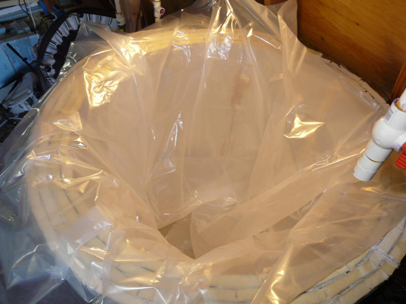
Starting to work the lining into the tank.
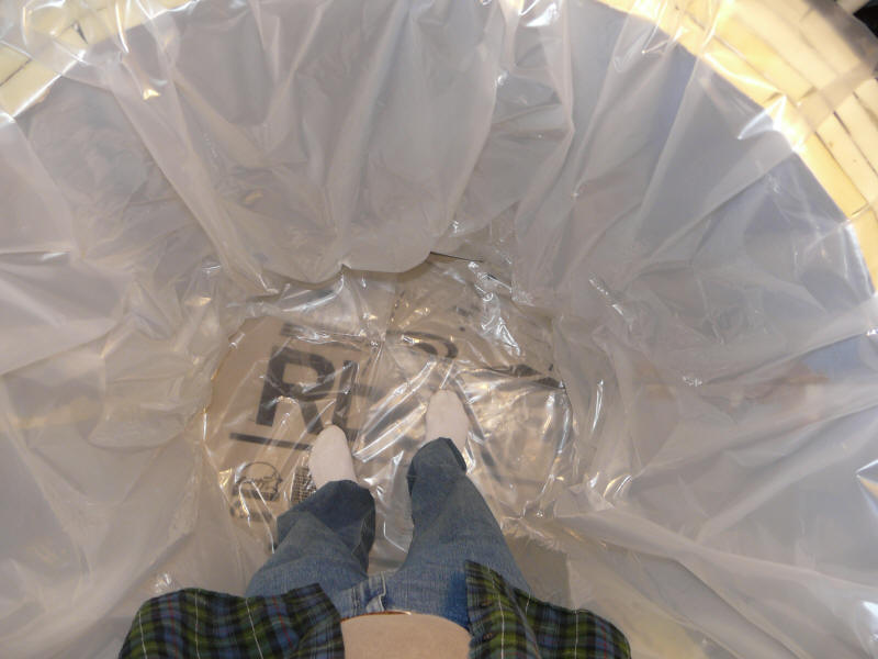
Getting in with shoes off to work lining up
against the insulation without any
bridging.
Filling the tank slowly while watching for
any signs of unsupported lining.
You will hear some snap crackle pop as the tank fills and the water pressure
pushes the insulation out. The tank get progressively stiffer as the
water pressure increases.
Putting the tank together is not difficult -- I'd not hesitate to recommend
to someone with no DIY experience.
I used water from our rain water collection system to fill the tank because
it has low mineral content. While I don't think that scaling would
be a problem on these systems unless you have very hard water, it was easy to
eliminate the possibility by using rain water.
I have to apologize to Tom at AmericanSolarTechnics for not trimming back the
liner and lid to make the tank look neater, but, for now I'm still changing
things around and don't want to do anything that might limit further changes.
Plumbing and Pump
I'm using CPVC pipe for this project. For those not familiar with CPVC,
its a type of rigid plastic pipe that is approved for domestic hot water
plumbing. It uses glued fittings, and the pipe is easily cut with a
scissors like device. Using CPVC is in keeping with
trying to keep it a simple DIY project -- the CPVC goes together easily and does
not require special tools or special skills. Its also easy to fix goofs. PEX or copper would also work
fine.
I've used 3/4 inch throughout the collector circuit. For systems with
longer runs or more collector area, 1 inch may be needed. The
pump sizing procedure will tell you...
Since this is a drain back system, the plumbing has to slope continuously
down toward the tank.
The pump I'm using is a Grundfos 15-58 3 speed cast iron pump. I have
used this pump on several projects and I like it. Its good for
temperatures up to 230F, the three speeds offer some flexibility on static head
and flow rate, its built like a tank, and the price is reasonable ($85).
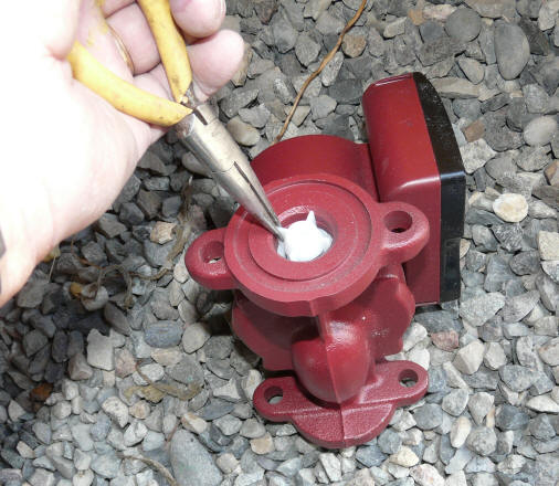
The pump comes with a check valve built into it, which must be removed for
drain back systems --pic below.
Removing the built in check valve -- this is a MUST.
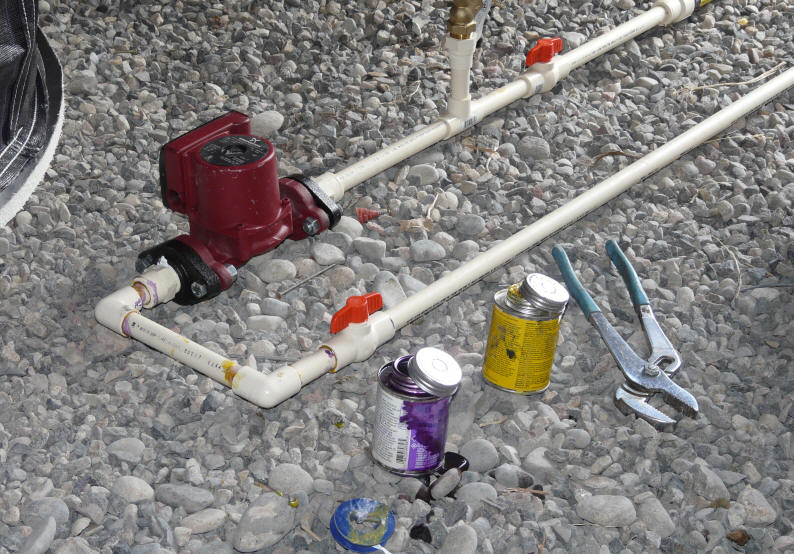
The pump came with 1 inch threaded flanges. I used standard CPVC
fittings to adapt from the 3/4 CPVC supply line to the 1inch flanges.
This shows the plumbing laid out on the floor before being put in place.
The pump mounted into the 3/4 CPVC supply line. The line to the right is
the U-tube that
goes up over the tank wall and then down to the bottom of the tank. The
U-tube allows
the pump to maintain its prime without having any low penetrations of the tank
wall.
The picture above shows the plumbing setup around the pump that I'm using for the prototype. There is
more here that would normally be used in a regular system.
- Pump is on the bottom with the u-tube going from the
bottom of pump up and over the tank wall -- it goes down inside the tank to
about 3 inches from the bottom of tank.
- The red handled valve at the bottom of the u-tube
allows the pump to be removed without syphoning water out of the tank (the valve
is hard to see in the picture because its facing away).
- The red handled valve above the pump in conjunction
with the hose faucet (green handle) allows the pump to be primed by hooking a
garden hose up to the faucet and running water INTO the faucet to flood the pump
and u-tube with water. The pump won't self prime, so some means must be
provide to prime it.
The faucet valve can also be used to add water to the tank.
You need a double female hose fitting to adapt the male end of the garden hose
to the male faucet -- hardware stores sell these.
- The lower vertical tube and valve to the left were
added for testing so that I can divert the drain back water into a bucket to see
how well its draining and measure the volume. Not needed on a "production"
system.
- The yellow gadget is a flow meter that can be used to
measure flow rate. It is positioned so that the middle of the flow valve
is at the target water line for the tank, so it can also be used to check the
water level in the tank. The jury is still out on whether this is a good
way to go.
The valve to the left of the flow valve allows the flow valve to be bypassed in
order to evaluate how much the flow meter resistance effects drain back.
For most drain back systems, the plumbing above the red handled valve would
just be a single straight run upward.
I have been less than thrilled with the inclusion of the flow gage.
Rather oddly, its quite noisy -- it sounds like a pump with air in it.
This is the 2nd of these gages that has had this noise problem. It slows
the drain back flow a bit. It is not very easy to actually see the tank
water level in the flow gage, so it does not work that well as a sight gage.
If I could find a simple and cheap transparent section to put in the line where
the flow gage is now and that would show the tank water level and just give an
indication when water is flowing, I think that would be fine. Any ideas?
The pump is a Grundfos 15-58 three speed. It runs fine on the lowest
speed, and the power consumption for pump and controller is 53 watts as measured
using a Kil-A-Watt meter.
The pump should be placed as far below the tank waterline as possible to
increase the static head at the pump inlet -- these pumps will not work if the
head at the inlet gets to low.
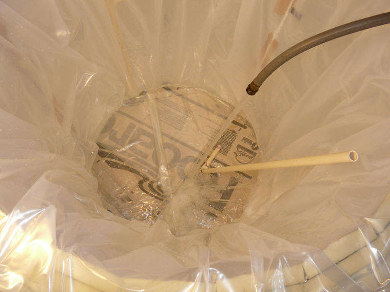
This is the return line coming back to the tank from the collectors without
the lid on the tank.
The return line MUST be terminated above the tank water line so that air can
flow up the return line during drain back.
The green cast of the water is probably algae. I filled the tank from
our rain water collection system to get water with low mineral content, and it
has a little algae growing in it. My experience is that as soon as the
water in the tank gets heated up to a high temperature, the green will
disappear.
Any thoughts or ideas on the pump and plumbing? Go to
comments....
Controls
The controller is a standard differential controller from
www.sun-pump.com model SR208C. It
provides all the bells and whistles and costs about $90. I have been using
one on my other system for more than a year and it has been doing fine.
The controller reads thermal sensors on the collector and in the tank.
When the collector temperature exceeds the tank temperature by a margin that you
set, the controller turns the pump on. The pump runs as long as the
collector temperature stays above the tank temperature by a margin that you set.
The controller has many other extra functions that can be used optionally to
control various odds and ends.
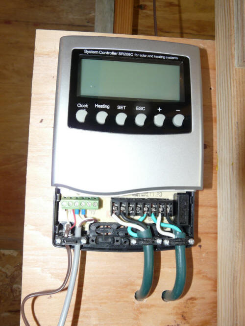
Picture above shows the differential control wiring. The right green
wire plugs into a wall outlet. The left green wire goes to the pump.
The left brown wire goes to the collector temperature sensor. The left
grey wire goes to the tank temperature sensor. All of the wiring is easy
DIY -- just push the wire in and tighten the screw terminal.
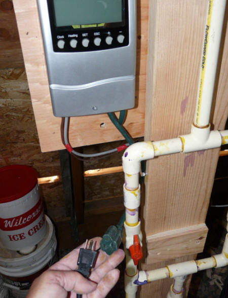
In the picture above, the pump power output from the controller is wired to a
female plug, and the pump is connected to the male plug. This is an easy
way to allow the pump to be run independently of the controller for testing or the like.
This can be made by just cutting an extension cord in half.
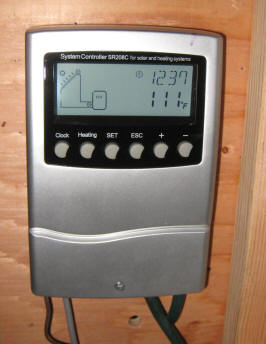
Normal display on controller
Thermal Sensors:
The tank thermal sensor and wire are pushed into one of the vertical
insulation board joints and then siliconed over making sure that no sharp edges
that could cut the lining are exposed. You want the sensor close enough to
the lining to have good thermal contact, but not exposing anything that might
cut the lining.
Picture shows the sensor wire entering the tank and going down the vertical
insulation board joint. The sensor is installed at the same level as the
pump
intake pipe -- about 3 inches from the bottom of tank.
The collector thermal sensor is currently installed on the top surface of the
collector embedded in silicone caulk. The jury is still out on whether
this is a good placement and mounting technique -- any ideas?
comments....
Heat Exchanger
The heat exchanger is not installed yet.
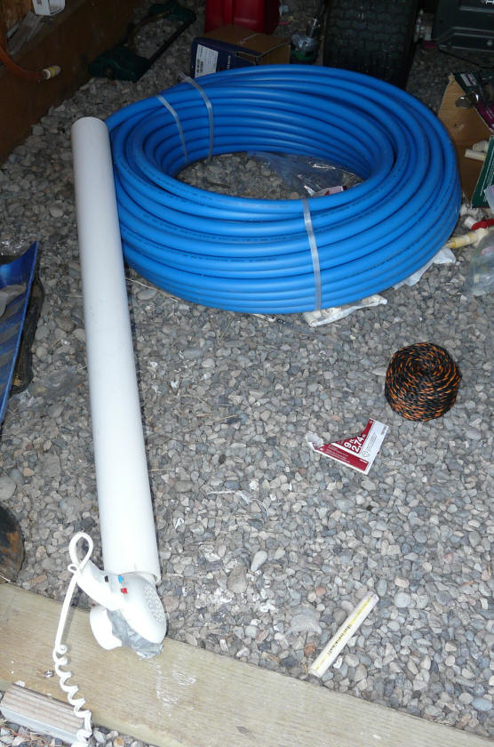
The heat exchanger is a 300 foot coil of 1 inch diameter PEX.
The incoming cold water makes a single pass through this heat exchanger coil on
its way to your regular hot water tank. This is the same system that I use
in the $1K system. The pluses and
minuses are explained on this
page...
I'm still mulling over how to hang the heat exchanger in the tank.
Leaning toward putting the coil in near the top of the tank and flat as in the
$1K system. The ends of the PEX would be bent up 90 degrees and exit the
tank vertically at the tank sidewall. Pictures below is an attempt
at forming the bend -- works pretty well, but the PEX tends to want to go back
to its original shape.
While the bend is a bit awkward, I would like to avoid the use of any
fittings inside the tank.
Heating the first few feet of the PEX coil
with a pipe and hair dryer prior
to bending.
The heated PEX bent upward 90 degrees
to exit the tank.
The plan is to support the coil in the tank with polypropylene rope.
When the coil is full of water, its has very little weight (nearly floats), but
I would like the supports to be able to support the coil even if the tank water
is drained, and I would rather not have it hanging on the PEX pipe inlet and
outlet.
Once the coil is in the tank, I plan cut the bands holding it in a coil, and
separate the PEX coils using short T shaped pieces of half in CPVC -- this will
improve the heat transfer from solar tank water to the PEX coil water.
Any ideas on best way to get the coil end out of the tank and/or how to
support the coil? Or, anything regarding this or alternate heat exchanger
designs? comments....
Performance General
The performance of the pool collectors is quite good for warm sunny days --
typically better than glazed collectors. But, as the ambient air gets
colder and the water gets hotter the losses that go with no glazing lower the
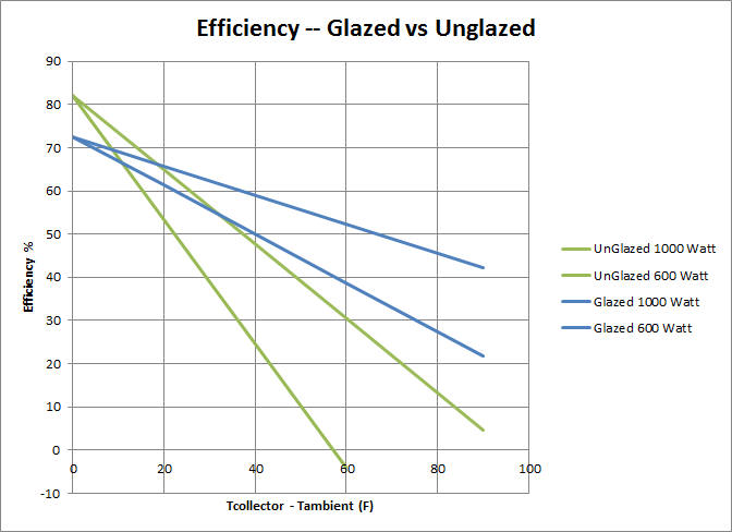
efficiency rapidly. These efficiency curves show the effect.
The plot shows the efficiency of typical glazed and unglazed collectors with
full sun (1000 watts/sm) and part sun (600 watts/sm) plotted against the
temperature difference between the collector absorber and the ambient air. For
example in full sun, an unglazed collector operating with an absorber
temperature of 110F and an ambient midday temperature of 70F, would have a
temperature difference of 40F, which gives an efficiency of 48%. This
might be typical of summer and part of spring and fall.
As expected pool heating collectors are good for warm days and moderate
hot water temperatures -- they actually beat glazed collectors in this area
because they don't have the glazing transmission losses. But, as ambient
temperature goes down, their efficiency falls off rapidly, and performance in cold
weather is poor. To a degree, this can be made up for by increasing
collector size as the collectors are cheap, but when the absorber to
ambient temperature difference gets above 70 or 80F, you are not going to be
making much hot water with an unglazed pool collector. Luckily in most places the
high temperature differences don't exist for much of the year.
One option I want to try this winter is to glaze the collectors with glazing
that allows a limited amount of airflow between the glazing and the collector.
The idea is to limit the convection losses, but at the same time the air leakage
keeps the stagnation temperatures from destroying the collector. Don't
know if this will work or not, but there is one commercial pool heating
collector that uses this design...
Unglazed collectors from various manufactures also vary somewhat on the slope
of their efficiency curves, and it might pay to pick one of the lower slope
models.
Another idea of Nick Pine's is to use greenhouse polyethylene, which (unlike
most glazing) is transparent to far IR heat radiation from the absorber.
So, the absorber would be able to radiate heat during stagnation events more
readily -- albeit with some loss in efficiency.
Lest you think using pool heating collectors is a totally nutty idea,
Fafco offers a solar water heating system based on their pool heating
collectors. Consumer Reports rated it the best of the ones they tested
based on its good economic return. Unfortunately, Fafco does not sell it
for DIY installation and does make a whole lot of data about it available.
They do offer some rough estimates of performance in different climates.
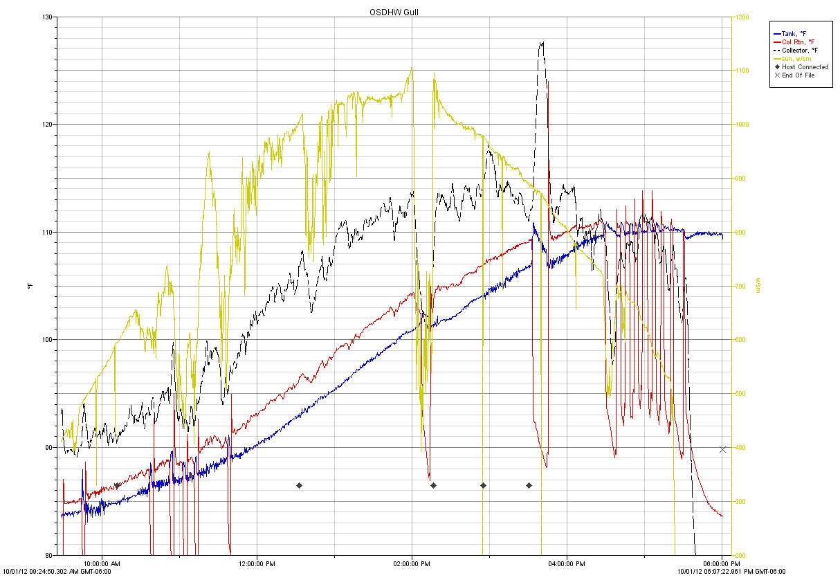
This configuration has been up for two days, and the data below was from the
2nd day of testing -- October 1, 2012.
The sun levels were measured with an Apogee Pyranometer that was mounted in
the plane of the collector. Temperatures were measured with an Onset
Computer U12 logger. The supply and return sensors were mounted directly
within the supply and return lines at the storage tank.
Blue line is pump inlet and tank temperature - degrees F
Red line is collector return temperature - degrees F
Black line is the collector surface temperature measured about 1.5 ft up from
the bottom of the collector -- degrees F.
Greenish line is sun intensity -- watts/sm
The occasional big drops in return line temperature indicate when the
controller has shut the pump down. The return pipe empties and the
temperature sensor in the return line drops toward ambient temperature fairly
quickly.
Just after 3pm, an experiment was done with adding partial glazing to the
collector, and at 3:45 pm the pump was intentionally shut down to see what the
stagnation temperature with the glazing in place would bet -- see section below
on glazing.
This was a pretty sunny day with some periods of high thin clouds and some
short periods of more serious clouds, but, overall a good sun day. There
was just a little forest fire smoke haze, but not much.
The tank had 132 gallons for this test -- this is less than its maximum
capacity, but even the 132 gallons is probably a bit too much storage for 40 sqft of
collector (3.3 gallons/sqft).
The tank temperature started at 83.8F and progressed up to 110.2F by end of
day. So, the system gathered: (132 gal)(8.3 lb/gal)(110.2F -
83.8F)(1 BTU/lb-F) = 28900 BTU over the day.
If one person uses 15 gallons of hot water a day, that requires about 7000
BTU to heat. So, on this sunny and fairly warm day, the system provided
enough hot water for 4 people. Pretty respectable for one 40 sf
collector.
The flow rate as measured by the fill time for a 2 gallon bucket was 4.6
gal/min.
So, at about 1:30pm with 1042 watt/sm sun, the collector was warming the
water from 98.8F up to 102.0F (+3.2F). So, the rate of adding heat
to the tank was: (4.6 gal/min)(8.3lb/gal)(3.2F)(60 min/hr)(1 BTU/lb-F) =
7330 BTU/hr (or 2148 watts). The total solar power input to the collector
at this time was about: (40sf)(1sm/10.76sf)(1042 watt/sm) = 3873 watts
input. So, the rough efficiency is (2148 watts out)/(3873 watts in) = 55.5%.
At this time, the difference between the absorber temperature and ambient
temperature was about 100F - 70F = 30F -- so, the actual efficiency matches the
efficiency predicted by the generic unglazed collector plot above almost exactly
-- wow :)
Short Cycling
The system does show some short cycling at the end of the collection period.
This may have to do with finding an ideal location for the collector temperature
sensor. Right now it is siliconed to the top collector surface just below
the return line. I did play around with the controller turn on and turn
off differentials without much apparent benefit.
Ambient Temperatures
This is the ambient temperature over the test period. Started at around
50F at the start of the collection period, and got up to about 74 F for the
high.
Over the night of Oct 1-2, the tank lost about 3F (109F down to 106F).
I believe that once the top is correctly sealed in place, the overnight drop
will will drop.
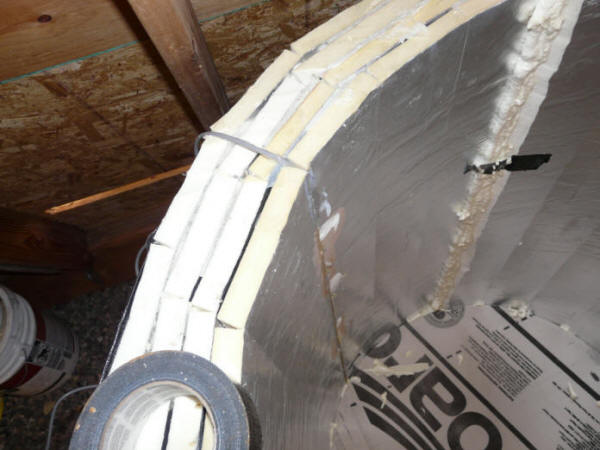
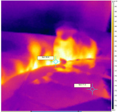
This thermal image of the top of the tank clearly shows areas where heat
leakage is occurring because the tank lid is not sealed down.
IR pics
This is a picture of the collector while operating. The temperature is
nice and even indicating that all of the collector is getting good flow.
The temperature rises about 3F from top to bottom as expected.
Preliminary Test of "Leaky" Glazing
One of the things I would like to test for colder climates is to provide
glazing over the pool heating collector. The glazing will have some air
leaks around the edges or on the top and bottom to allow a little ventilation
between the glazing and the collector and keep the polypropylene collector from
being damaged by high temperatures in a stagnation (no water flow) event.
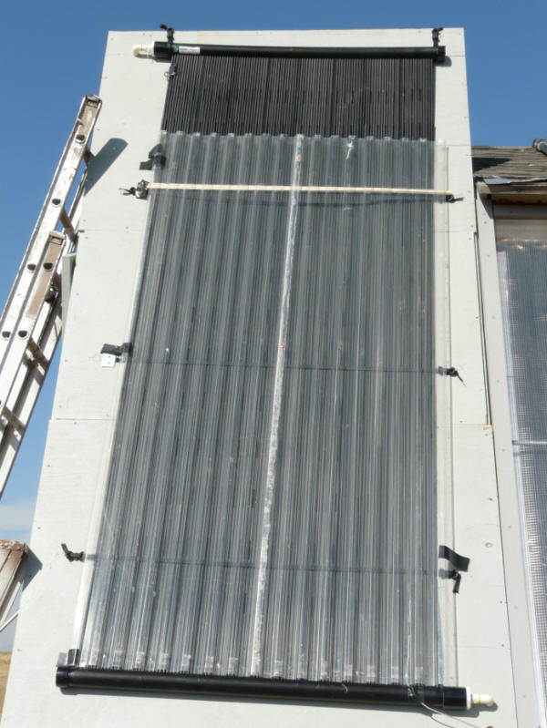
I have an old 4 by 8 ft test collector lying around, and decided to use its
glazing to get a quick idea how the "leaky" glazing concept might work.
So, I just laid the 4 by 8 glazing over the bottom of the new collector.
The bottom of the glazing rests on the lower manifold, and the glazing is taped
on at a couple places along each edge. Near the top, a spacer strip of
wood was inserted between the glazing and the collector to keep them separated a
bit. This was not a carefully installed setup, but just a quick
"opportunity" test -- the gap between the glazing and the collector was poorly
controlled and variable.
The glazing is corrugated polycarbonate -- SunTuf.
The quick glazing test.
It was a bit surprising how nicely it just sat there.
On the performance plot above, the glazing goes on at 3:05 pm, and comes off
at 4:04 pm. The pump flow was stopped at 3:34 pm until 3:45 pm to
simulate a stagnation event.
Its hard to spot any definite change in performance due to the glazing.
This is a time period when the sun levels are dropping fairly quickly, and that
may be obscuring the performance benefit of the glazing, or the glazing may have
had too much air leakage area, and, not covering the top 20% of the collector
did not help. I guess I would call it inconclusive. A more careful
test will be needed to get an idea what the benefit is. At the 4:04 pm
when the glazing comes off, there does appear to be some drop in the collector
temperature rise as one would expect if the glazing was helping performance --
but, hard to say for sure.
The pump shutoff at 3:34 pm does show a spike in the collector surface
temperature at about 127F (up from 112F just before). This is still well
within the collectors rating. Poking around with the IR temperature
gun and another thermometer, absorber temperatures up to 140F were noted --
again, this is well within the collector rating.
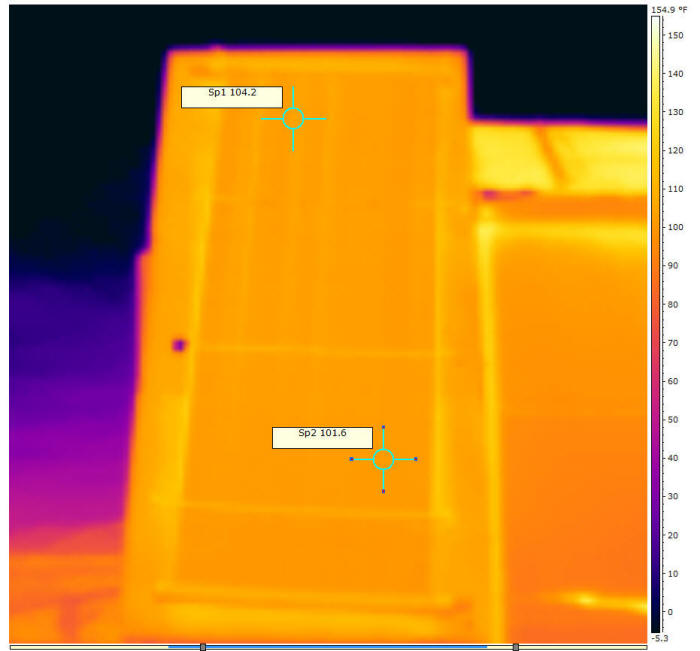
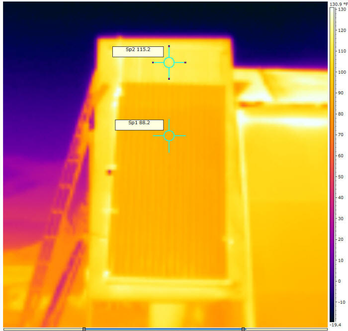
This is a thermal image with the glazing installed.
The 88.2F area is the temperature of the glazing (not the
absorber), and the area above at 115.2F is the absorber surface that was not
covered by the glazing.
The glazing temperature is surprisingly (to me) uniform.
This picture was taken when the collector was getting a
full flow of water.
Update March 15, 2013:
1- A more careful test of the glazing concept shown just above was
tested. It covered the full collector from manifold to manifold,
but otherwise looks just like the one shown above.
Some testing of this concept showed very little improvement in collector
efficiency, so I went on to ...
2 - A more conventional glazing system was built and tested.
Complete details on the revised
glazing system here...
The revised glazing setup shows some significant improvements in
performance and may be a good option for colder climates.
Gary
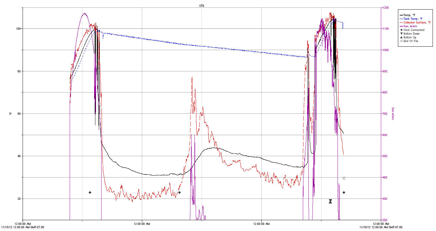
November Test -- Unglazed
The plot below shows how the system did for 3 days in November
(11/15/12 through 11/17/12). The first and last days were sunny, and the
middle day was overcast with low solar input.
On the first sunny day, the 130 gallons of tank water started at about 75F,
and got up to about 97F by end of day. About a 22 F heatup for 130
gallons, or about 24,000 BTU.
Ambient temperature got up in the 30F area at mid day. There was no
glazing on the collector.
This seems pretty respectable to me, and appears to indicate that even in
cold climates, the system can provide some useful heat through the winter on
sunny days.
The final day was similar to the first with a gain from 87F to 105F.
On the middle day, the system never turned on due to low sun levels.
Cost
Here is a rough cost breakdown:
Collector -- 48 sf with mounting hardware $250
(assuming one 4 by 12 collector is used)
Tank -- Softank
$219 (plus shipping)
Tank insulation
$150 (local)
Pump -- Grundfos 15-58
$85 (plus shipping) (Wilo 3 speed would have done as well at
$54)
The system qualifies for the 30% federal tax credit, and may qualify for
state or other rebates. For example in MT (where I am) it would qualify
for the $500 renewable energy tax credit. The reason that this system
qualifies for the federal tax credit and the regular $1K system does not is that
the collectors are SRCC certified under the OG100 program.
For me, if I did not already have a solar water heating system, this system
would be essentially free with the $500 tax credit from MT (one for me and one
for my wife), and the federal tax credit.
Comments
I am very interested in hearing any thoughts or suggestions you might have
during this time when its still easy to change the design.
Here is an email comment from Kennith:
Hi Gary,
I was thinking on the pool collector glazing- stagnation question. The
pool collector is designed to withstand stagnation in the summer with no
wind(I thing it is? ) I think the main reason for glazing is to trap air
next to the absorber(no wind). With regular glazing the heat under the
glazing will move to the top and overheat the top of the collector in a
stagnation event(Unless vented big time). I was thinking about a lot of
small wind guards made with polycarbonate. like the attachment