Search
The Renewable Energy site for Do-It-Yourselfers
DIY PV System --
Building the Mounts
Back to the PV
System page...
This section covers the thinking that went
into the mount design, and the construction and installation of the PV panel
mounts.
The
Mount Design
Why we
chose ground mounts in the first place is covered here...
The goals for the mount system were:
- Strong enough to withstand very
strong winds. Even though this is normally a low wind area, we do
occasionally get storms with high winds. I did not want my PV
panels to end up in the next county.
- A long life. The panels will
probably last for 30 years, so it seems like the mounts should last just
a long.
- A simple, uncluttered look.
- As cheap a system as meeting the
above goals allowed.
This is all highly subjective, and there
are no doubt lots of good ways to get to a good mounting system, but this is
what we did.
We considered buying a metal racking
system. Several of these are offered. We decided against this
partly on cost grounds and partly because I like the look of a simple wood
rack better than a forest of metal poles. But, the advantage of going
with a metal rack would be that you get a pre-designed system that should go
together easily and hold up well -- these are advantages worth considering.
Either way, you have to dig and pour the concrete footings, which is the
biggest job.
I settled on the simple treated lumber
support rack that is made using relatively heavy (4X4) members spaced fairly
far apart. I thought that this looked cleaner and would be easier to
build than a more elaborate trusswork of smaller members.
The PV kit that I bought came with
IronRidge aluminum rails to mount the PV panels to. This is a very
nice system which does a good job of securing the panels and micro
inverters. Standard IronRidge hardware that came with the kit was used
to secure the PV panels to the rails, and to splice the rails together.
There are other manufactures of similar systems.
|
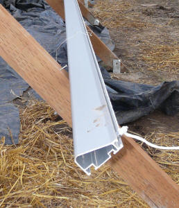
Aluminum rails that panels mount to. |
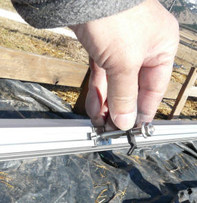
Slide in mounting hardware to attach PV panels |
The spacing of the 4X4 supports is based on
the wind table provided by IronRidge showing basically that if the rail is
supported at 7ft or less intervals, using their "L" brackets that it will be
good for very high winds. I spaced the 4X4 supports at just over 6 ft
to be on the safe side.
I had a rough look at wind loads on each of
the 4X4 support structures, and concluded (at least to my satisfaction) that
they were up to the loads that the rails would impose on them with very high
winds. But, I'm an airplane guy, not a wind guy, so if you use this
design you should satisfy yourself that its OK for the loads.
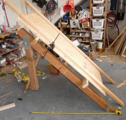
Working out the mount geometry in the shop -- the plywood
represents
the PV panel, and 2X4's the alum rails.
While I was waiting for the system to
arrive, I set up a little mockup in the shop to
work out the details of the 4X4 support
structure. Yes -- I agree -- my shop does need a good cleanup.
The longevity of the treated lumber may be
an issue in some areas, but around here, properly built treated lumber
structures last a very long time. Even untreated poles do well in this
climate. I took pains to repaint cut edges with preservative, and to
provide extra treatment for exposed ends and the portions embedded in
concrete. I also used strong, double shear, galvanized metal plate
joints.
I decided that the bottom of the PV panels
should be about 1 ft off the ground. This may seem kind of close to
the ground for an area that gets a fair bit of snow, but it has worked out
fine for the solar thermal panels we already have. Even though we get
regular snow storms through the winter, the amount on the ground at one time
almost never exceeds 18 inches, and panels 12 inches off the ground seem to
accommodate this fine. To my way of thinking, mounting the
panels further off the ground just makes the mounting structure more
complex, increases loads, and looks worse. If you are in a part of the
country that keeps accumulating more and more depth through the winter, then
you may have no choice but to go higher.
I also considered using two racks with 5
panels each instead of the 1 rack with 10 panels. Either way would
work fine, but the one rack of 10 panels seemed easier and less cluttered to
me. If you use two rows of panels, be sure the first one does not
shade the 2nd one -- use the SketchUp method for this.
My first thought was to make sure
that the rack was level across the full width, but the ground is slopped
enough that this would have raised one end of the rack about another foot of
the ground. So, instead, I established a line that was 12 inches off
the ground on the east end and the west end, and connected these with a
straight line. So, while the rack looks level, it actually slopes down
about 1 ft over the 33 ft length.
Its downhill toward the house, so the
electrons have gravity on their side.
I considered building the mounts so
that the panel tilt could be adjusted by time of year -- steeper in the
winter for the lower sun and less steep in the summer for the higher sun.
I ran PVWatts for tilts of 30 deg, 45 deg, and 60 degrees, and then picked
the highest output months for each tilt. I compared the yearly output
for multiple tilts to the output for a constant tilt all year of 45 degrees.
The increase in yearly output was very modest. The extra complication
of a variable tilt mount and the ongoing chore of changing the tilt several
times a year did not seem worth it to me, so I settled on a fixed tilt of 45
degrees -- this allowed for a very simple and strong structure.
Again, this is all rather subjective, and
there are probably lots of good ways to do it. The important thing (I
think) is to make sure the mounts are strong enough to stand up to
your winds, and that the type of construction you use has demonstrated a
long life in your area.
Building the Mounts
In order to have a good platform to
mount the aluminum rails on, it was necessary to make sure that all 6 of the
4X4 support frames were in good alignment with each other. The L
brackets used to mount the aluminum rails to the supports have slotted holes
that allow for about a half inch of adjustment, but that's it.

All six support
frames need to be carefully aligned along the surface that
the rails will be
attached to.
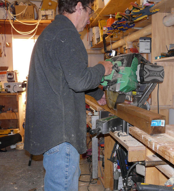
Building the Frames
Once the dimensions of the support
frames were established using the little shop mockup shown above, I cut and
built all 6 frames.
Click on pictures for full size
|

Cutting the frames -- set up a stop,
and make all 6 cuts. |
Add extra treatment to cut
edges and the part to be in
the concrete.
|
|
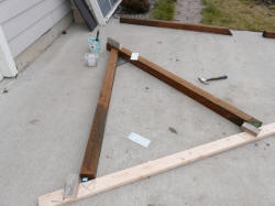
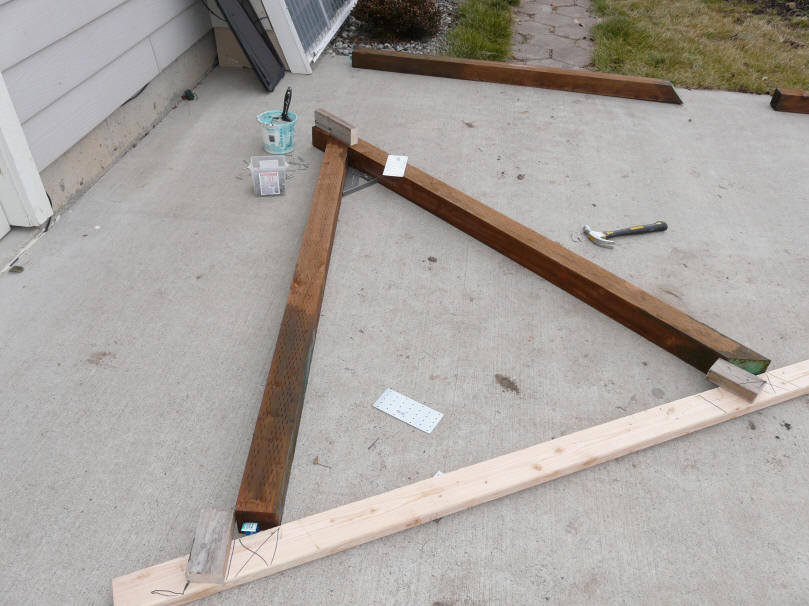
I used this simple jig made from
a 2X4 to assemble the frames.
|
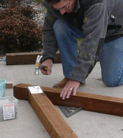
Galvanized plates used on both sides
of the frame provide a good, double shear
joint. I used joist hanger nails. |
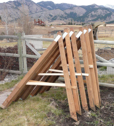
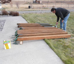
All six frames
ready to go. The scraps of wood
hold the angle
right until the ends are in concrete.
Digging the Holes
The next step is laying out and
digging the holes for the concrete footings. In all 12 footings are
needed -- one for the back of each frame, and one for the front.
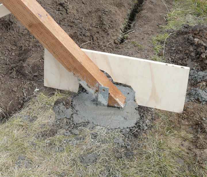
The back (vertical) frame member is
embedded in the concrete about 20 inches. The front frame member (the
angled one) is attached to the fitting via a galvanized U strap that is
embedded in the concrete. As shown just below.
|

Back frame in concrete. |
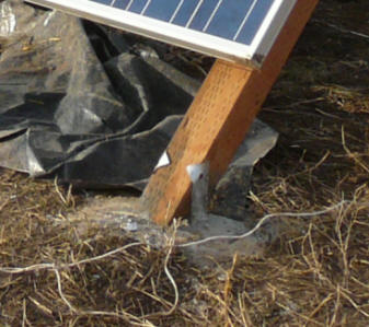
Front frame attached with U strap. |
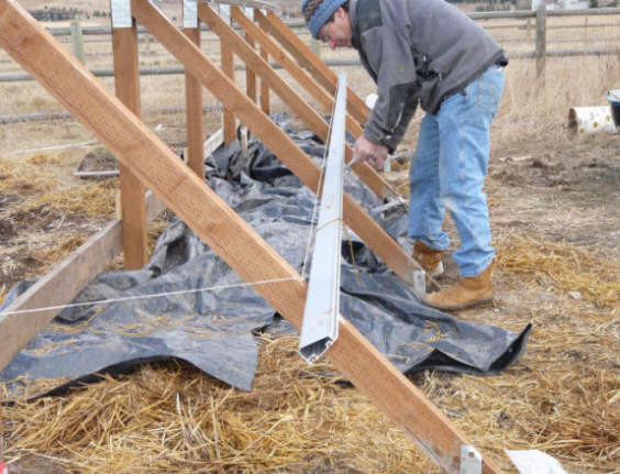
I used stakes and strings to get the
footings in the right place.
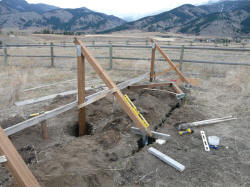
In order to make it easier to get the
frames lined up, we put a temporary support along the back edge of the
frames as shown in this picture. Its important to get this frame in
with the 2X6 at the right height and straight over the full 33 ft width --
each support frame is temporarily screwed to this 2X6 guide for alignment
until the concrete sets. I think that without some kind of guide
structure like the 2X6 one shown, it would be a nightmare to get all 6
frames lined up properly.
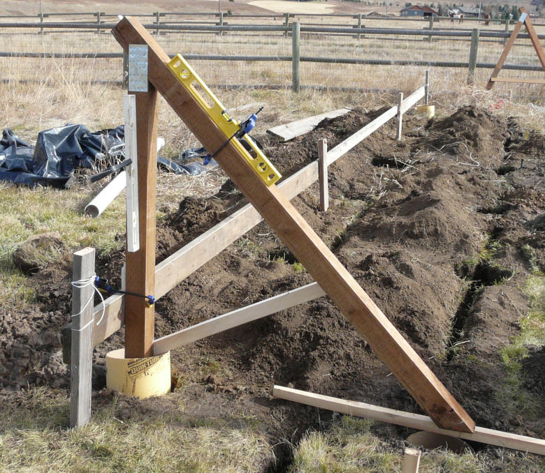
This picture shows the temporary 2X6
frame that supports the back of each of the frames until the concrete is
poured and set.
Note the small block of wood screwed
to the back face of the vertical frame member -- this allows the frame to be
easily placed at exactly the right height.
The two end frames were installed
with quite a bit of care to get all the heights and angles correct.
The 45 degree bubble on the level gets the right angle and the block of wood
on the back of the vertical member setting on top the 2X6 temporary support
gets that frame height right. Screwing the vertical 4X4's to the 2X6
guide insures that all the frames are in a straight line.
Pour the concrete for the two end
frames and let it set so that these frames are solid, and can be used as a
guide to set the other frames.
The Footings
The footing holes are about 12 inches
in diameter, and about 30 inches deep. I have a post hole auger for my
tractor, but this proved to be worthless in the hard, dry soil. I
ended up running two trenches with the rental trencher along the line of the
foottings. This gave me a 3 inch wide start on each of the footing
holes. I expanded them out to around 12 inches by hand with a shovel,
iron rod, and post hole digger. This worked well, but you do have to
really pack in the dirt around the footings where the trench is after the
concrete sets -- I used the heavy iron rod with a mushroom end for this.
click on pictures for full size
|
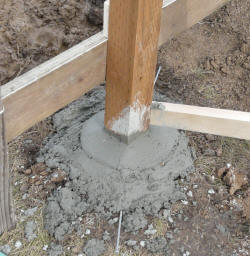
The back posts.
Concrete troweled to drain away from
the post. |
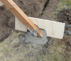
The front footings. The scrap of
plywood keeps the frame
member at the right height until
the concrete sets.
Concrete is troweled to drain away from
the frame, and there is a gap between
the concrete and the frame wood. |
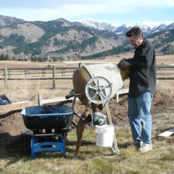
A small mixer helps a lot. |
In some cases, I used the Sonotube
cardboard forms, but mostly I just poured the concrete directly in the
holes.
My neighbor lent me his small
concrete mixer, and that save a lot of time -- thanks Don!
In all, 3200 lbs of dry premixed bags of
concrete were used, with the back footing holes getting a little more than
the front ones.
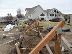
After the two end frames were in and
solid, I stretched a string between the two end frames at the positions
where the aluminum rails would be mounted, and started to mount the middle 4
frames. With the back 2X6 frame to guide and support the middle
frames, this all went pretty fast, and the end result was that all the
frames aligned well.
click on pictures for full size
|
Mounting the middle frames. Using the
string, back 2X6 guide supports, and
45 degree level to get things lined up. |
Middle frames positioned and ready
for concrete.
(the wonky metal plates were replaced
with the right kind later) |
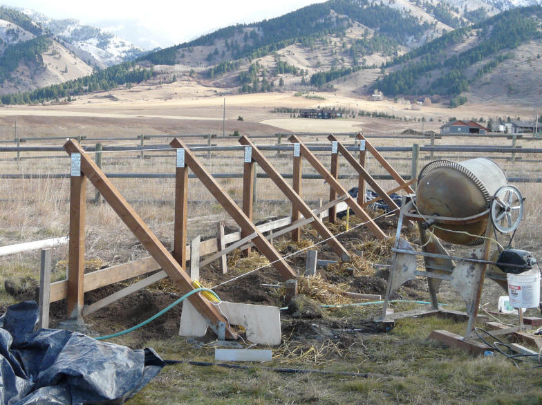
All six frames in
and aligned with footings poured. The straw is to protect the
concrete from expected night time freezing conditions.
So, this system worked pretty well, and the
mounts seem very solid, and well aligned.
Cost was roughly: treated wood $100,
concrete $130, other miscellaneous $50 = $280ish
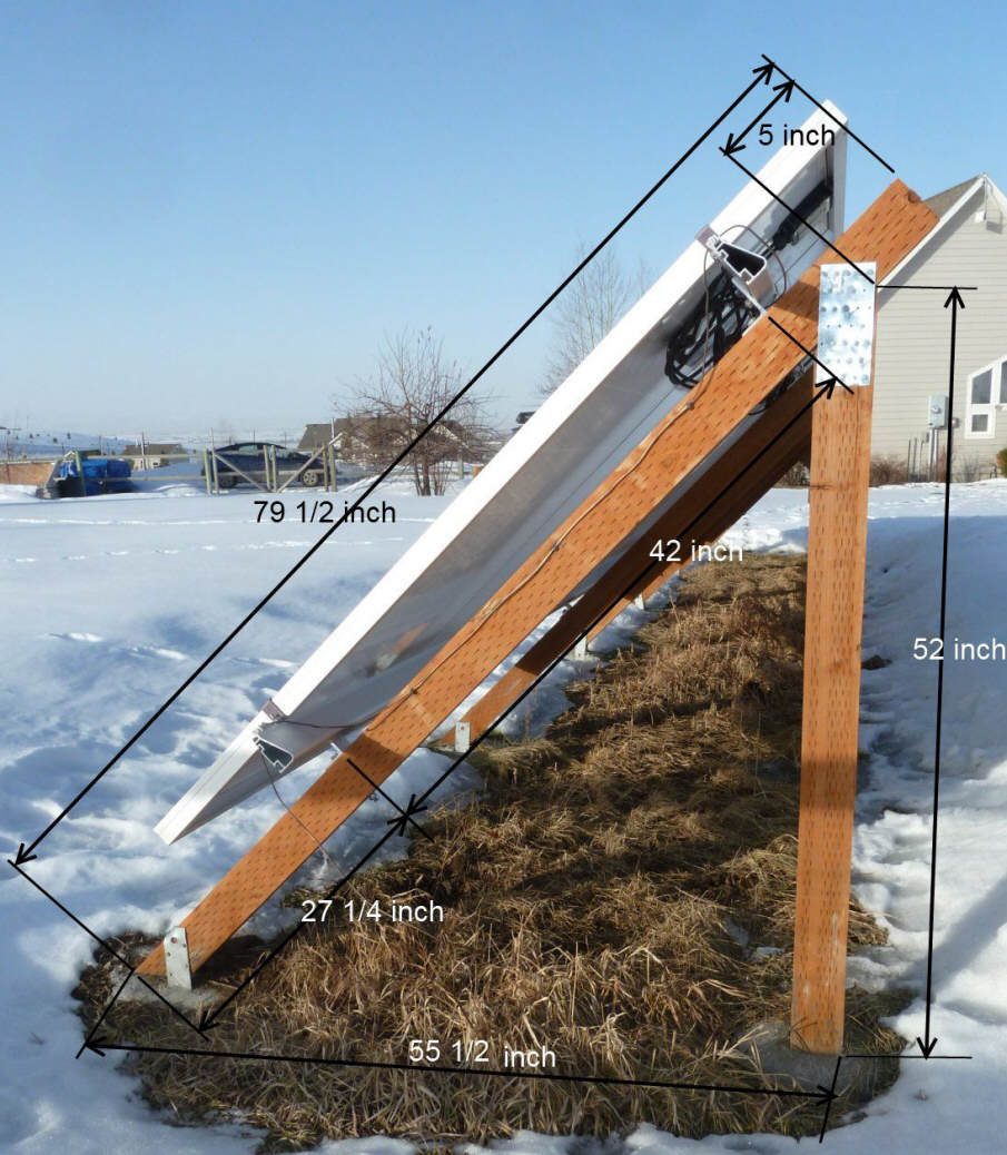
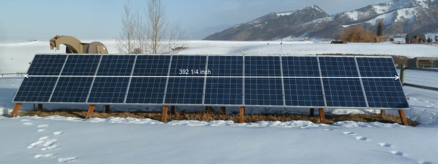
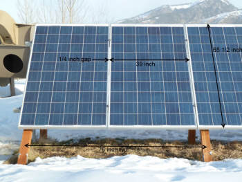
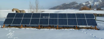
Dimensioned Pictures
These are the dimensions of the
mounts for my system. You will, of course, have to adjust them for your PV
panels and situation.
| Click on pictures for full size |
 |
| |
 |
| |
 |
Gary November 20, 2009, February 15, 2011