
Search
The Renewable Energy site for Do-It-Yourselfers
$2K Solar Space
+ Water: Collector
Plumbing and Pump Design
This section covers how you go about adapting the collector loop plumbing
and pump design to your particular collector size and to the elevation
distance between your tank and your collector.
| The section also covers the rules you need to follow in plumbing the system in
order to have a good reliable drain back system that will last a long
time and never freeze. The sizing and installation of the collector
loop pump.
And, alternatives for situations when drain back systems
cannot be used are discussed
.Back to Table of Contents..
|
 |
|
|
Rules for Plumbing a Drain Back
System
These are the rules that you must
carefully follow to have a drain back system that will drain reliably and give
good freeze protection:
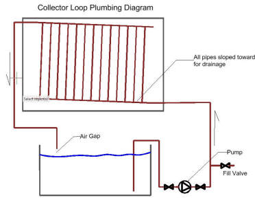
- The supply and return line
between the solar storage tank and the collector must all have a continuous
slope down toward the tank.
This allows all the water in the plumbing and the collector drain back to
the tank when the pump turns off.
This is critical for freeze protection.
The slope should be at least 1/8 th inch per foot, but 3/16 th or a 1/4 inch
is better.
Be careful to support non-rigid lines (eg PEX) often enough so that they
can't sag enough to take the down slope out.
- The bottom of the collector
must be above the water line in the tank so that water can gravity drain
from the collector down to the tank.
- The collector absorber array
must also be tilted such that it will also drain. The corner where the
supply line enters must be the low corner of the collector -- see picture
below.
- All of the lines to the
collector should be at least 3/4 inch in diameter. Smaller
diameter lines may not drain back reliably.
- The risers in the collector
should not be smaller than half inch for good drain back. This rule is
sometimes broken, but you are taking a bit of a chance.
- The return line must terminate
above the water line where it comes back to the tank. That is, there
must be an air gap between the end of the return line and the water line in
the tank. Without this air gap, the collector will not drain, because
there is no place for the air that is needed to replace the draining water
to get in.
- The pump must be constructed in
such a way as to allow water to flow back through it into the tank during
the drain back. All of the common pumps will do this, but I would be
suspicious of self-priming pumps.
Some pumps (eg Grundfos) come with a check valve
installed to prevent reverse flow -- this must be removed.
Drain back systems are the simple and
highly reliable and provide excellent freeze protection, BUT, you have to follow
the rules above or all bets are off.
I have two drain back systems that
have been operating for years through our -30F Montana winters with absolutely
no problems at all.
Sizing the pump
In a nutshell, the pump must met two
basic requirements:
- When the system starts up, the
pump must be able to get the flow established by pumping water from the tank
up to the top of the collector. This requires that the pump have
enough pressure head at startup to get water all the way to the top of the
collector and a bit extra to get some flow going. Once the collector and return line
fill, the required pump pressure drops because the return line pressure
recovery balances the supply line pressure requirement.
This startup pressure gets more and more important as the collector
elevation above the tank increases.
For many systems this startup
head will be the main factor in picking the pump.
- The 2nd requirement is that the
once flow is fully established that the pump provides enough flow to remove
the heat from the collector efficiently.
This
pump sizing procedure for drain back
systems will lead you through the whole process...
Installing the pump
Most of the pumps used in drain back
systems are not self priming. This means that the pump casing must
retain its charge of water after the drain back completes, or it won't be
able to pump on the next startup.
Keeping the pump case full of water is
normally accomplished by mounting the pump below the water level of the
storage tank. If your pump is a submersible, then this is pretty
much automatic, as the pump just sits inside the storage tank. But,
most pumps are not submersible. For non-submersible pumps, there are
two ways to keep the casing full of water:
- Run the inlet pipe for the pump
through the storage tank wall below the water level. This can be
done with an EPDM lined tank by (very carefully) using a bulkhead
fitting that is made for this purpose. There is an obvious
opportunity for a leak here, but if done carefully, this approach can
work fine.
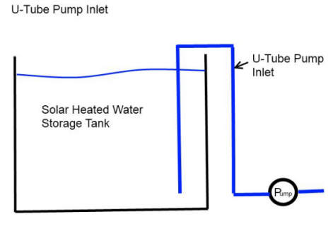
- The more commonly used method is the
run the inlet pipe for the pump from the bottom of the tank, up over the
side of the tank, and then down the outside of the tank to the pump.
this is called a U-tube inlet because its in the shape of an inverted U.
Once the U-tube has been filled with
water and purged of air, it (and the pump) will retain their charge of
water during drain back, and will start up fine the next time.
Most of the pumps used in these systems
require that there be some positive water pressure at the inlet of the pump.
This is best accomplished by mounting the pump as low as possible so that
the depth of the water in the tank provides the needed inlet pressure.
This is why we mounted our pumps down as close to the floor as we could.
Pumps can be sensitive to pressure losses in the U-Tube, so if your system
is a relatively high flow rate system, you should go to 1 inch pipe for the
U-Tube.
When first starting up the system, it is
very important to purge all the air out of the pump inlet line. If the
pump makes noise while running, it very likely still has some air bubbles,
and needs to be purged again. Note the valves on our system to
allow the use of a garden hose for purging air and filling the pipes.
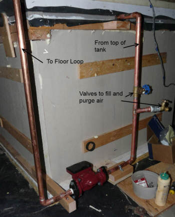
Picture of U-Tube inlet on floor loop pump.
PV Powered
Pumps
It is possible to use a PV panel
driven pump to power this system. The obvious advantage is that it does
not use any power from the AC mains, and this saves some money on electricity
and some carbon emissions. I will say up front that I am not the biggest
fan of the PV powered pump for this system for these reasons:
- There are some who say that its
the perfect match because the PV panel can not only power the pump, but it
can also be the pump controller. The idea is that the PV panel will
only generate enough power to run the pump when the sun is out, and that's
exactly when you want the pump to run. I believe that this does not
work nearly as well as it would appear at first glance for these two
reasons:
-
The PV panel does not
know anything about the temperature of the water in the storage
tank, and this is important. When the water in the tank is
fairly hot already, the system needs to wait longer to turn the pump
on -- basically there has to be more sun because the collector has
to be hotter than the already pretty hot storage tank. On the
other hand if the storage tank temperature is cool, then the pump
can turn on earlier because the collector does not have to be that
hot to warm the cool water from the tank up. A direct driven
PV pump will turn start the pump when the sun reaches a certain
level regardless of tank temperatures -- sometimes this will be just
right, but other times it won't, and the consequence will be that
the system might actually cool the water in the tank instead of
heating (the hot tank situation), or some water heating energy will
be missed because the tank water is cool and the pump could have
turned on earlier. For a regular pump that is controlled by
differential controller, this does not happen because the control
knows the temperature of both the tank and the collector, and can
turn the pump on at the right time.
This same problem can happen again as the sun is going off the panel
in the afternoon.
-
The other problem that
can occur is due to the fact that the efficiency PV panels and
thermal panels have opposite dependencies on temperature. PV
panels get more efficient as it gets colder, and solar heating
panels get less efficient as it gets colder. This means
that if the PV panel is setup so it starts the pump up at just the
right time when its (say) 50F out, then on a morning when its (say)
20F out it will start the pump to early because the PV panel is more
efficient and generates the pump startup current with a lower sun
level, while the solar thermal panel is less efficient and actually
need a higher sun level to get to a temperature that is right for
startup.
So, for those two reasons I don't
think its a good idea to use a PV panel directly driving the pump. Its
not that it does not work, but its not (I think) an efficient way to go,
especially in cold climates.
I'm not alone in thinking this as
evidenced by the appearance of several differential controllers that are
specifically made for systems that run a pump off a PV panel. These
controllers run on PV power, and the combination of one of these controllers
a PV panel and a suitable pump does overcome the two problems mentioned
above, but this is getting to be a pretty pricey solution.
Other reasons things to consider
for PV pumps:
- You will likely pay a fair bit
more for the PV solution, and I think that if you put this extra money into
just making your collectors larger you will come out far ahead in net energy
saving. If it costs an extra $200 for the PV pump solution, this could
be used to add nearly 30 sqft of additional collector, which would generate
an additional 1300 watts of power under full sun conditions.
That's a whole lot of power compared to what it costs to run a regular AC
pump.
- If you have or plan to do a
grid-tie PV system, I think its more cost effective and simpler to just add
a little capacity to that system to drive your solar heating system pump.
This is not only cheaper and simpler, but it will get benefit from times
when the sun is out but the solar heating system is not running -- say in
the summer when the tank is already heated to its maximum temperature.
- If you pick an efficient pump
that is powered off the AC mains, the energy it uses compared to the energy
the solar heating system produces is just very small. However, pump
power can become significant if you pick a low efficiency pump, or one that
is much larger than is really needed.
- If the collectors are well
above your tank (for example your tank is in the basement and the collectors
are on the roof), then it will be hard to find a pump that will provide the
startup head to get the flow going and still be a pump that can be powered
by PV.
Or, if your solar heating
collector array is large and requires a fairly high flow rate, it may be
difficult to find a pump that can be PV driven that is large enough.
If you do decide you want to drive
the pump from a PV panel, then I would keep these things in mind in selecting
the PV panel and pump and controller:
- For the reasons mentioned
above, it would be good to use a differential controller -- see the Controls
Section for some examples of ones that work with
PV...
- For a drain back system, the
pump needs to be able to put out enough head at startup to get the water up
to the top of the collector. This takes more power from the PV panel
at startup than is needed at startup for a closed loop system. So, its
good to make sure that the PV panel larger enough to provide the needed
power in the morning. A linear current booster can also be used to
help the pump get going on less sun.
- Also, bear in mind that not all
DC pumps are suitable for running direct from a PV panel. The pump has
to be able to tolerate a fairly wide range of voltages. Some pumps (eg
the Laing D5 pumps) are made to be driven by PV and even have
hardware/software in their electronics to maximize the PV panel output (MPPT).
This all sounds a bit complicated,
and it is more difficult to bring it all together on a drain back system, but
its possible -- I ran the $1K solar water heating system from a March DC pump
and a 16 watt PV panel successfully for quite a while.
Alternatives to Drain Back
If you find for any reason that a
drain back system will not work in your situation, then you can probably switch
over to a closed loop system.
Going to a closed loop system can
make sense if:
- You cannot locate your storage
tank below your collectors.
- Your collectors are so far
above your storage tank that you can't find a pump with enough startup head
to get a drain back system started.
- It is not possible to install
the plumbing from the collectors to the storage tank with a continuous down
slope.
To build our system as a close loop
system, you need to make the following changes:
- Use non-toxic antifreeze in the
collector loop plumbing (this provides your freeze protection). The
antifreeze must be checked each year, and replaced when needed.
- Add a heat exchanger to
transfer heat from the collector loop to the solar storage tank. In
most cases, this can be a coil of copper pipe immersed in the solar tank
that carries the collector loop fluid.
The heat exchanger could be similar to the ones used in
commercial drain back tanks like this one...
One company appears to use a
heat exchanger sizing rule of about 20 sqft of collector area per 1 sqft of
heat exchanger area...
- Add an expansion tank,
pressure/temperature relief valve, and fill valves to the collector loop.
A good source of information for
installing closed loop systems is the Home Power article on closed loop systems
that is listed in the Basics section of
this page ...
References
Gary Feburary 16, 2011
