Search
The Renewable Energy site for Do-It-Yourselfers
Making or Buying
Fins for Solar Collectors
& Evaluating Fin Designs
|
Many of the homemade
collectors shown on this site use aluminum fins to collect the incoming
solar heat and transfer it to a tube that carries the heat transfer
fluid. The fins typically have a groove of some type that fits
over the pipe to increase the heat transfer area from the fin to the
pipe.
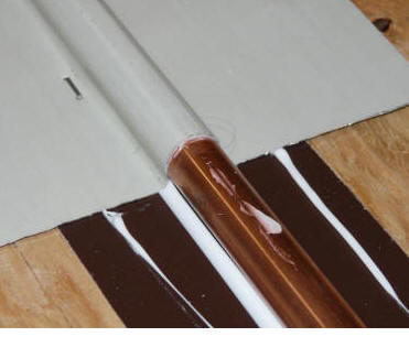
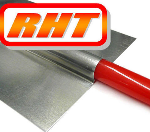
The
grooved aluminum fin wraps over the copper pipe
for good thermal contact.
|
|
This page summaries the various ways
that people have gone about making these fins, and also provides some places
that you can buy commercial fins.
The page also provides some
construction tips, and provides the calculated performance (fin efficiency) for
several designs.
Directory for this page:
Homemade Fins
-- several designs...
Bought fins
-- several types and sources...
Construction Tips -- a few tips on making good fins...
Fin Material (including one free source)...
Fin Efficiency
-- the performance of homemade and commercial fins...
Homemade Fins
You can do a good job of making
collector fins in your shop. Here are several methods.
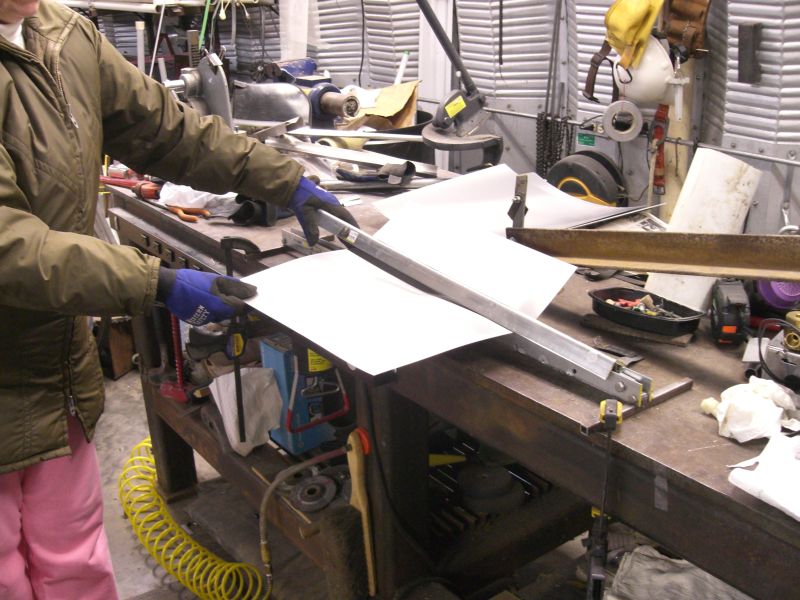
Sledge Hammer Press
This is the method I've used for the
last couple collectors I've done. It seems crude, but it actually works
well, and makes a nice fin.
Click on pictures for full size
|
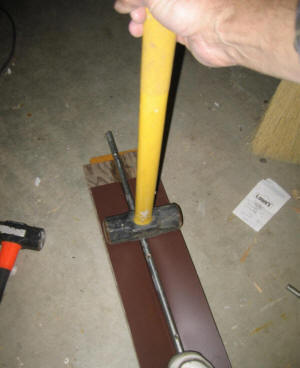
Using the groove forming tool. |
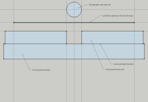
Cross section of groove forming tool.
(click to enlarge) |
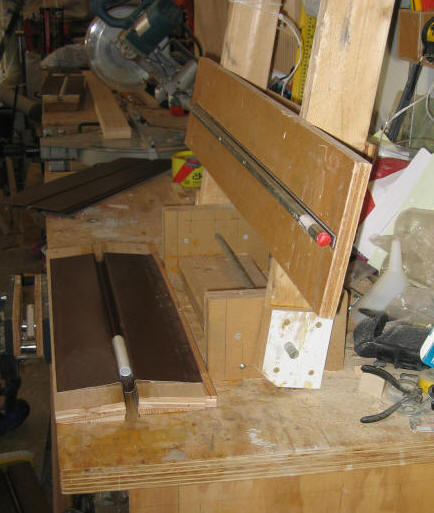
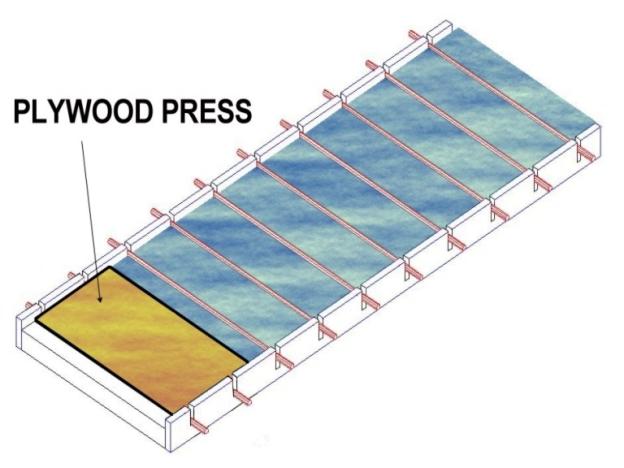
The tool consists of a plywood form with the
groove shape in it, and an ordinary 5/8th inch diameter solid steel rod.
The form is made from scrap plywood.
The base is about 3 ft long and made from 3/4 inch plywood.
The slot that forms the groove is
made from two pieces of 5/8ths plywood setup so that there is a 5/8 inch wide
slot formed between them. These two pieces should be carefully glued and
screwed to the base -- they take a beating during the forming process.
I've been using
Rollex System 3 aluminum roof
soffit material for the fins. I cut them to size on a table saw, but
they cut easily with any kind of saw or shears. This brand comes with some shallow preformed
grooves already in the right place, and I just put that groove into the slot in
the tool, lay the 5/8 ths steel bar into the preformed groove, and bang on it
with the sledge hammer. I hold the sledge as shown in the picture above,
and move the handle straight up and then straight down. Basically,
bang on the fin with the top the hammer, not the head of the hammer. Using the
sledge in this way keeps the fin flatter.
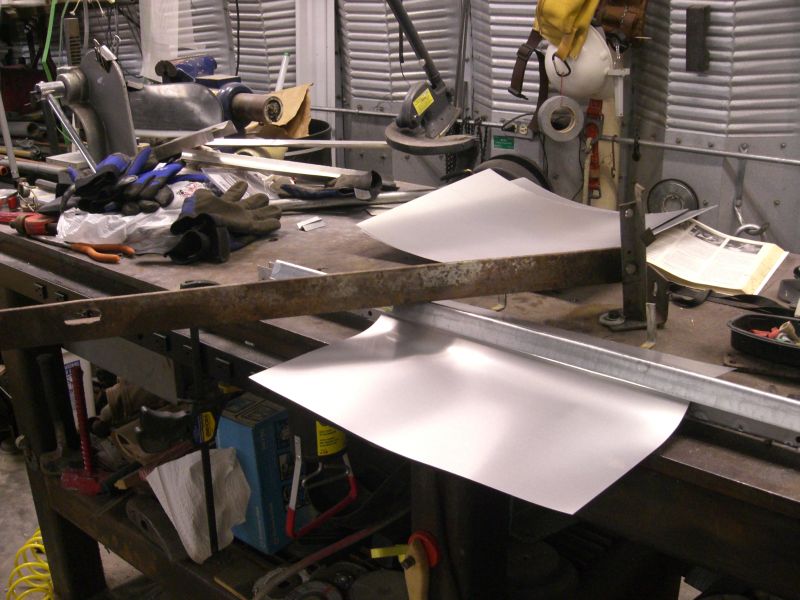
You can use one foot to keep the
steel rod in place for the first few swings.
Once you get the hang of this, its
quite fast -- maybe 15 to 20 seconds per fin.
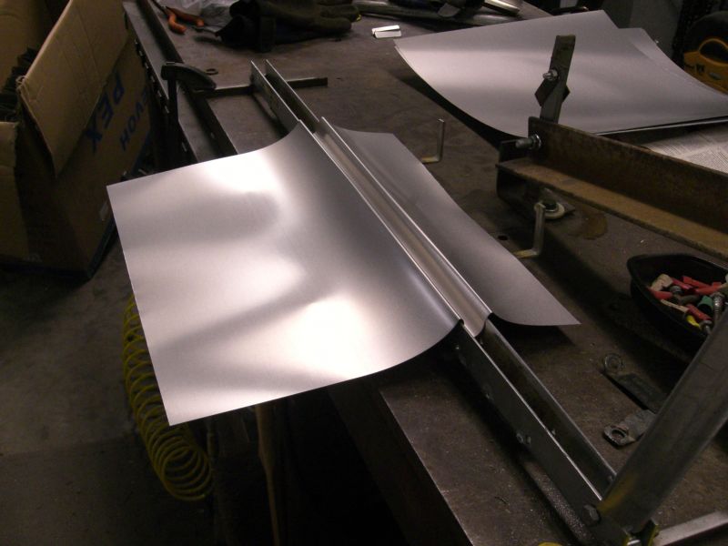
Be sure to check the first few fins
for good fit -- make any adjustments that are required to get a snug fit.
If you were starting from flat stock
aluminum, you would want to add some vertical pins (eg nails) to the form on
both ends of the form to guide the steel
bar -- one pair of pins at each end of the jig. This will keep the steel
rod centered over the slot in the plywood form. It would also be good to
add a stop along one side of the form to position the fin so that its centerline is over
the grooving slot.
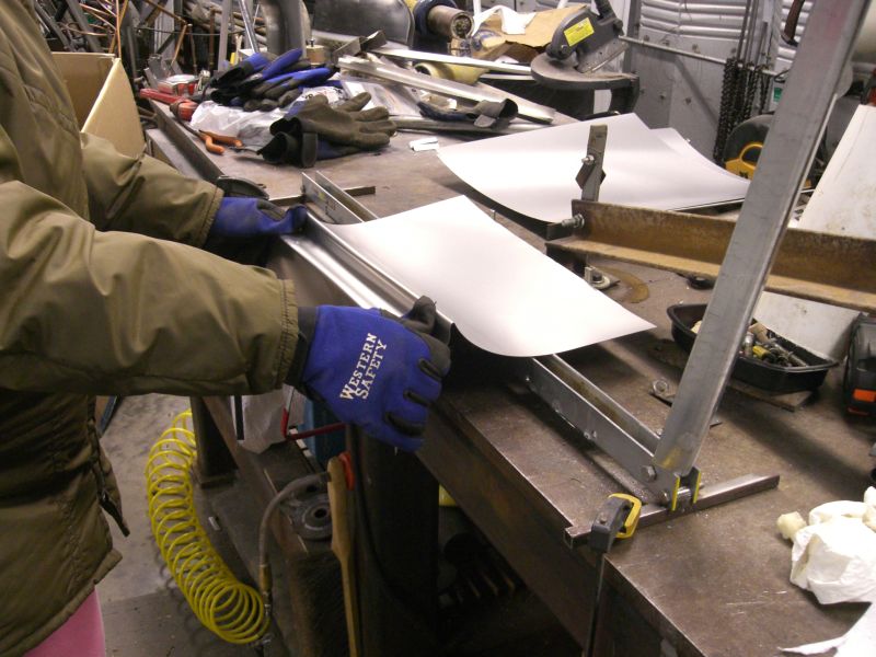
When installing these fins over the
copper tubing, its very important to really bear down on the stapler so that the
fin gets pulled down into tight contact with the copper all over. The fin
to tube joint can be a thermal bottleneck if you don't pay careful attention to
maintianing good tight contact over the full joint area. There is more
info on the absorber assembly process at this link
More detail on the fin making on this page...
Fins made with the sledge hammer
method have been
tested against copper fins continuously soldered to copper pipe and they do
quite well... The key is to maximize fin to copper tube contact area,
and to keep the gap between the fin and the copper tube zero to paper thin.
Except as noted, I think that all of these fins designs will deliver good
thermal performance.
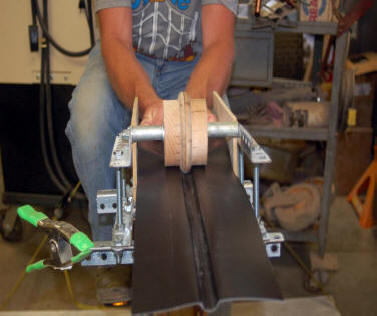
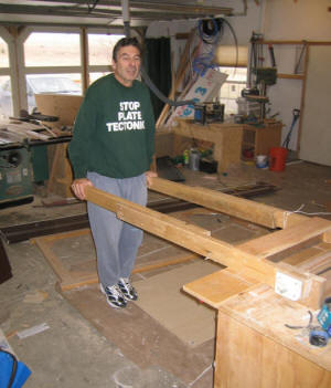
My Earlier Fin Press
I built this fin press on my bench
when I was making a lot of fins for my radiant floor heating. Its a bit of
work to get it setup and working right. In the end, it makes fins of about
the same quality as the sledge hammer method. For one person, its really
not that much faster than the sledge hammer method, so I don't see much benefit
in going to the work of building this.
If you had tons of fins to do, and
you could have one person pushing down on the press handles and a 2nd person
feeding and removing the fin sheets into the press, you could do a whole lot of fins
in an hour.
Click pictures for full size
|
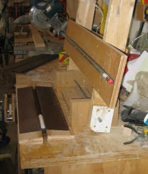
The press pushes the steel rod down
into the slot form. |
Long handles allow a lot of pressure to
be applied with just body weight. |
More detail here...
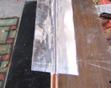
Two Layer Fins
Kevin worked out this method that
uses two thinner aluminum layers to make the fin -- one under the riser tube,
and one over the riser tube.
He used two layers of the 0.01 thick
and 9 inch wide aluminum flashing material that is commonly available in
hardware stores.
The first layer goes down flat on the
plywood backing, and the 2nd layer (which is grooved using something like the
sledge hammer method) goes over the top of the riser tube. So, you end up with 0.02 thick
fins and with aluminum in contact with the copper tube for nearly the full
circumference. Since the tubes are spaced about 6 inches apart, and the
aluminum fins are 9 inches wide, they overlap each other on the outer edges --
this probably improves performance a little bit. I think the
performance of this method should be quite good, and the materials might be more
readily available to you.
Full details on Kevin's design here...
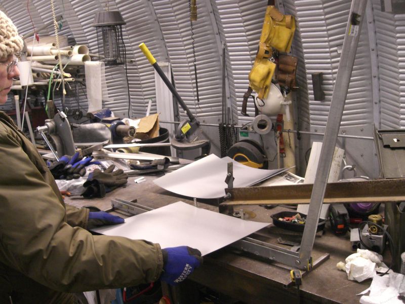
Fins from Printing Plates
Printers use aluminum plates as part of the printing process. Soren has worked out a way to use these aluminum plates for collector fins.
Collector fin being formed from a recycled printer's plate
Soren describes in detail how to make collector fins from recylced printers plates....
Full Wrap Fins
Henry worked out this way to make a
fin that fully wraps the copper tube.
Details on the
full wrap process here...
It seems to me that this fin design
will perform well, but it does look like it adds a fair bit to the labor side.
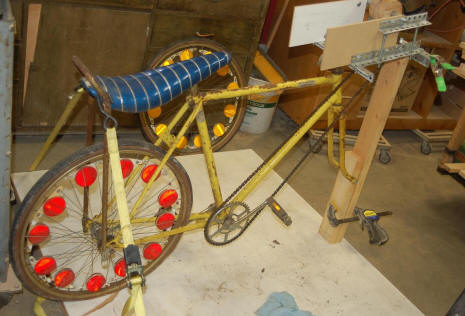
Matt's and Woodsy's Fins:
Matt worked out what is clearly the
coolest way to make the fins. He converted a bicycle to drive a forming
roller to roll the groove into the fins.
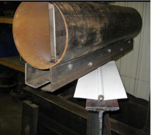
| Both Matt and Woodsy mounted the fins on the bottom of
the copper tubes such that the part of the tube not covered by the fin
is exposed to the sun -- as shown in this picture. The metal clip
pulls the fins into contact with the copper pipe.
My feeling is that this method does not result in as good a thermal
contact between the fin and tube as the methods discussed above, but
I've not tested this, and it may be just fine.
|
 |
Woodsy's collector is detailed here...
Matt's collector is detailed here...
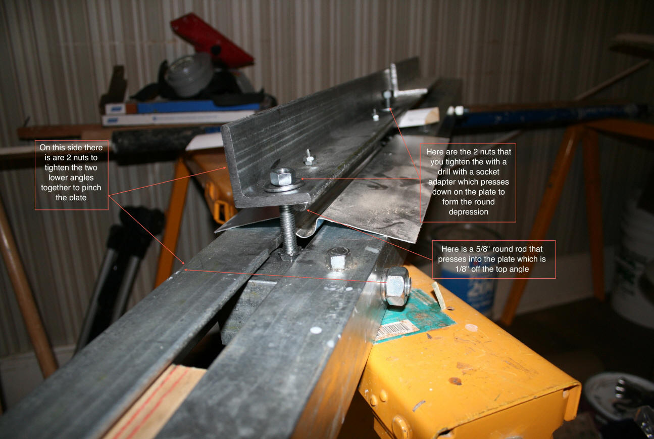
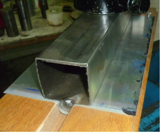
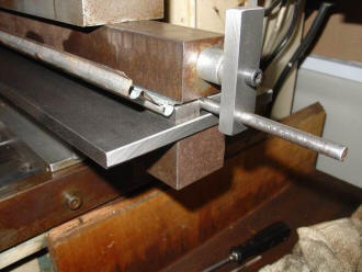
Anthony's Fin Making Machine
Anthony worked out the fin making machine shown in the picture below. The
top angle has a 5/8 rod fastened to the under side. The aluminum fin blank
is placed under the top angle and on top of the two lower angles. The two
nuts on the threaded rods are then turned with with an electric driver, pushing
the rod down onto the fin, and forcing the fin material into the slot between
the two lower angles. The two bottom angles can then be pinched together
by tightening the other two nets so that the fin gets a better wrap on the
tubing. Pretty neat.
Click on picture for full size

Anthony's fin making machine
Anthony reports that it takes less than 30 seconds to run the two nuts and make
a fine.
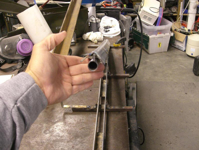
John's Fin Making Method
John Canivan uses this method to make
all the fins for a serpentine absorber from one sheet.
All the details here...
A Heavy-duty Press from Kris
This
fin maker uses a salvaged press ...
Kris does some amazing
machine shop work on his solar systems...
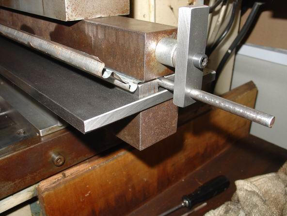
David's
Double Fin Method
The pictures below show a tool worked
out by David that makes a double fin.
Buying Fins
Tom's Fins
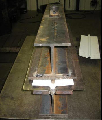
Tom Sullivan is a long time friend of
Build-It-Solar, and has
contributed a number of really well done projects
to the site. When Tom was making his collectors, he set up a dedicated
press to make
fins for his collectors. This is a very nice fin press, and makes fins
that fit really well, and wrap nearly all the way around the tube for good
thermal contact.
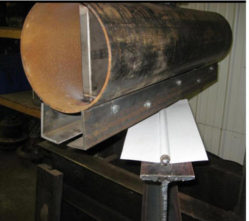
|
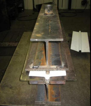
Stage 1 of Tom's press makes the groove. |
Stage two of Tom's press wraps the
aluminum further around a tube to
make for more contact area. |
More on
the press here...
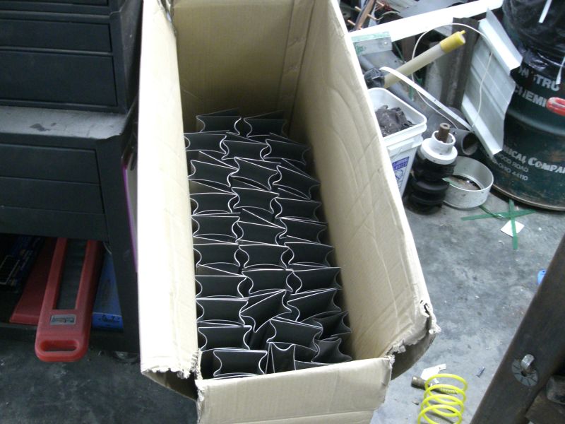
Tom ended up with a whole lot of
extra fin stock, and offered to make fins for people to use up this excess
stock. He has done this for a number of people, and may continue making
the fins after the initial stock runs out. If you want to talk
to Tom about making fins, the link above has contact information.
I got a batch of these fins for my
new collector (which is in work), and they are very nice -- they certainly offer
better thermal contact between the tube and fin than the commercial fins listed
below.
| |
Update on Tom's Absorber Plates
Tom has decided to make absorber plates from his press available as a
regular product from his UP Truck Center business.
He offers plates to fit 1/2 inch and 5/8 inch copper or PEX pipe.
Fin length can be customized from 24 to 34 inches. He offers a
"standard" fit as well as a 90% wrap fit. The modified vice-grip
that make it easier to clamp the fins tight to the tubes are also
available.
The prices are very reasonable, and I can attest to the fact that the
plate fit is very good. I think this is a very good option for
anyone who does not want to bother with making fins.
All the details on ordering and using the fins on
ordering fins from Tom... |
Commercial Heat Spreader Fins --
Formed from Sheetmetal
These are commercially available fins
that are made for use in radiant floor heating. They are aluminum sheet, usually
5 or 6 inches wide, typically made from 0.018 inch thick aluminum, and have a formed groove that fits
over the PEX floor loops in radiant heating systems. While I've not
actually tried these, it looks like they would do a descent job of transferring
heat from fin to tube.
If using these, I think it would be
worthwhile running the sheet of flat aluminum under each tube with the grooved
fin above that as discussed below.
Here is one example ...
This example is made from 0.019 thick
material, 5 inches wide and 24 inches long.
These plates are only 5 inches wide,
so you would need to place the riser a on 5 inch centers. I would still
recommend using the flat sheet of 3 inch wide aluminum directly under the tube
centerline.
These are bare aluminum and should be
cleaned and painted before applying over the copper tube to prevent corrosion --
see also the note on silicone caulk below.
Commercial Heat Spreader Fins --
Extruded
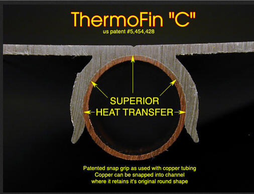
There are also commercial fins that
are heavier gage, and are extruded rather than formed from sheet metal.
The extruded shape snaps on the tube with a satisfying snugness.
I am sure these would work well, but
they are more expensive.
One example:
Radiant Engineering...
These particular ones are only 4
inches wide, so riser would have to be spaced 4 inches apart. At about
$6.50 per 4 ft length plus the cost of the added risers, this makes for a pretty
big price bump, but a collector built with these would still be a lot less
expensive than a commercial collector.
Note that the makers of these tubes
show 4 inch wide fins installed on tubes that are 8 or 9 inch centers.
This results in a 4 inch gap between adjacent fins. While this may be OK
for radiant floors, it is definitely NOT the right thing to do for solar
collectors. The outer edges of the fins on adjacent riser tubes should
touch each other.
These are bare aluminum and should be
cleaned and painted before applying over the copper tube to prevent corrosion --
see also the note on silicone caulk below.
Construction Tips
Silicone in the Groove:
I like the idea of applying a thin
bead of silicone in the groove of the fin before pressing it onto the copper
pipe. No matter how well formed your fins are, and how carefully you
fasten them in to position, there will be a very small gap between the fin and
the copper in some areas -- the silicone in 10 times more conductive than air,
so (I think) you are better off having silicone in the gap. The silicone
also glues everything together so thermal expansion and contraction don't
work the fin and pipe away from each other over time. In addition, the
silicone reduces any chance of galvanic corrosion by sealing out any water and
providing a protective coating. I known many people are skeptical of this
given that silicone is not a highly conductive material, but be sure to read the
link below before you leave out the silicone.
More detail and performance testing on the silicone in the groove story here...
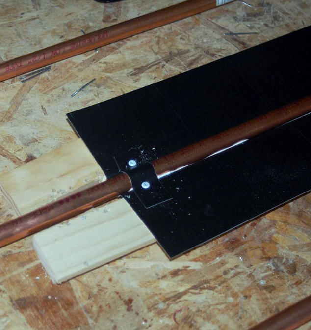
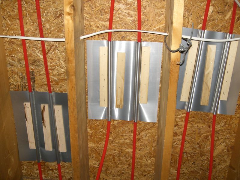
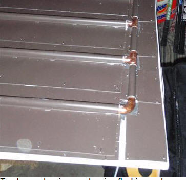
Narrow flat strip under tube:
I use a 3 inch wide flat strip of
aluminum under the center of each copper tube as shown in this picture.
The brown aluminum under tube is a
separate 3 inch wide strip of 0.018 thick aluminum. This extra aluminum
strip results in more contact area between the tube and fin, and also increases
the aluminum total thickness for heat transfer to 0.036 in the area where heat
flow is the greatest (the heat flow is zero out at the outer edge of the fin,
and greatest at the fin tube joint).
Type of Aluminum:
Some aluminum alloys and tempers are
very springy, and just don't take a groove very well at all. So, you need
to find out if the aluminum you want to buy is easy to form. I think its
best to buy a small sample and try it if you can.
Source of Material for Fins
There are several sources of material for fins.
For 5 or 6 inch wide fins you want aluminum that is about 0.018 inch thick (this is a common gage). And, you want it to be soft and easy to bend. The fins want to be thick enough to conduct the heat efficiently from the body of the fin into the tube -- this calculator will give you an idea how thick the fin needs to be as you increase or decrease the width of the fin.
Hardware stores sell rolls of aluminum flashing material. Normally this is thinner than you would ideally like -- 0.01 inch thick is the most common thickness. But, I have also seen the thicker gages on occasion. Its possible to use two layers of the 0.01 inch thick material with one layer being grooved to fit the the tube and the other layer running flat behind the tube -- similar to Kevin's system...
Another option is to use aluminum soffit material, which is usually the right thickness -- one example is Rollex System 3 aluminum roof
soffit.
Soren suggests that a good free or very cheap source of aluminum for fins is to use printers plates that have been used and are destined for recycling. These plates are commonly about 0.012 inch (0.3 mm) thick, so its good to use two thicknesses if you can. Soren used these for his collector and they worked quite well. Sizes range from 30X50 cm up to 120X160 cm.
Fin efficiency
Some of the solar references provide
a formula for calculating the efficiency of a fin. A fin that conducted
all heat to the tube without any losses (ie a made from a material with infinite
thermal conductivity) has a fin efficiency of 1.0. Fins made from
real materials will require that the outer edge of the fin run warmer than the
tube area of the fin in order to produce some temperature differential to
conduct heat into the center of the fin. This temperature differential
from fin edge to fin root increases the average temperature of the absorber,
which increases heat loss out the glazing, which in turn reduces the collector
efficiency.
Fins on commercial
collectors often have fin efficiencies in the mid 0.9's. The table just
below gives calculated efficiencies for several of the common homemade fins and
a typical commercial fin.
The fin efficiency depends not only
on the fin material, fin thickness, and fin width. It also depends on the
collector heat loss. The table gives efficiencies for both single and
double glazed collectors. The equations I used for fin efficiency come
from "Solar Thermal Engineering" by Peter Lunde, page 183 (a good solar
reference).
NOTE: that this calculation for fin
efficiency assumes that the thermal connection of the fin to the tube is perfect
-- that is, it only considers the fin up to the fin to tube joint, not the joint
itself. So, a fin has a high calculated fin efficiency can still blow it
all on an poor thermal connection to the copper tube -- looking around at some
of the Internet DIY designs, I think that this happens a lot.
| Fin Material |
Fin Thickness |
Total fin width
(inches) |
Fin Efficiency (single glazed) |
Fin Efficiency (double glazed) |
Delta T Across Fin
(degrees F)
(double glazed) |
| Aluminum |
0.018 |
6 |
0.91 |
0.94 |
14.6 |
| Aluminum |
0.036 |
6 |
0.95 |
0.97 |
7.6 |
| |
|
|
|
|
|
| copper |
0.008 |
4.5 |
0.93 |
0.96 |
11.4 |
| Aluminum |
0.05 |
4 |
0.98 |
0.99 |
2.2 |
| Aluminum |
0.05 |
8 |
0.94 |
0.96 |
10.2 |
| Steel |
0.018 |
6 |
0.65 |
0.75 |
62.6 |
The first entry is for the most
common of the homemade fins -- a 0.018 fin that is 6 inches wide. The fin
efficiency is 0.91for single glazed and 0.94 for double glazed which (I think) is fine.
The 2nd entry is for an aluminum fin
that is twice as thick. The configuration I like to use where the center
part is two thicknesses of 0.018 for 0036 total but the outer part is 0.018
thick would be somewhere between the first two entries -- maybe 0.96. So,
by adding the 2nd piece in the center only, you pick up a bit on fin efficiency
and also (probably more importantly) get more heat transfer area from fin to
tube. Where the 2nd advantage does not apply to the fin designs that wrap
or nearly wrap the full tube diameter (like Tom's and Henry's).
The third entry for the 4.5 inch wide
copper fin is typical of commercial collectors -- at 0.96 its about the same as
the homemade aluminum ones -- the advantages of the more conductive copper and
narrower fin are offset by the very thin material typically used in the
commercial fins.
The 4th entry is what you would get
if you used the extruded aluminum fins mentioned above. The thick and
narrow fin brings the efficiency all the way up to 0.99, but at a pretty high
dollar price.
The 5th is for a fin like Steve
Baer's (Zomeworks) "Big Fin" -- it shows that you can get good fin efficiency
with very wide fins if you go with a thick fin. The thick material
will make it harder to form the groove in the fin. I think the Big Fins
use more of a clamping arrangement between the fin and tube.
I get emails asking about using steel
for fins. The last entry changes the material of the fin in row 1 from
aluminum to steel. Steel has only about 1/6th the conductivity of
aluminum, and this causes the fin performance to really drop. If you want
to use steel fins, they would have to be narrow and thick to work well.
The last column gives the delta
temperature from the outer edge of the fin (the hottest part) to the root of the
fin at the tube (the coolest part). If you assume that the average
collector temperature goes up by half the amount of this delta temperature you
can get a rough idea what this costs in collector efficiency using
this calculator.
For example, if picking a typical
flat plate collector, 40F ambient temp, 110F tank temp, 300 BTU/sf-hr sun, and a
value of 8F for the fin delta T (from above table), the collector efficiency
drops by about 1.2% compared to the same collector with a perfect fin.
Gary Feb 21, 2010